Tri-polarization Reconfigurable Fabry-Perot Resonator Antenna in Ku-band
Shichao Zhu, Jiagang He, Jie Yu, Yang Feng, Shaopeng Pan, and Gaosheng Li
1College of Electrical and Information Engineering, Hunan University, Changsha 410082, China
zsc_08@163.com, 609288490@qq.com, antennayujie@hnu.edu.cn, fengyang@hnu.edu.cn, shaop1128@163.com, Gaosheng7070@vip.163.com
Submitted On: February 3, 2022; Accepted On: September 3, 2022
Abstract
In this paper, a broadband tri-polarization reconfigurable antenna applied to polarization diversity is proposed. A partially reflective surface (PRS) is designed to form an air-filled resonator cavity. The reflection phase of the PRS has a positive phase gradient in order to achieve the characteristics of the proposed antenna gain enhancement in the wideband. A metal patch of a four-arm meander structure is used as the radiation structure and the feeding is realized through a four-channel rotating feeding network with equal amplitude and 90 phase difference. The feeding network is connected to the radiation structure through four metallized vias. In order to realize the polarization reconfigurability, the PIN diodes and the corresponding DC bias circuit are integrated in the rotating feeding network. The characteristics of horizontal polarization (HP), vertical polarization (VP) and right-hand circular polarization (RHCP) are realized by changing the ON/OFF states of PIN diodes integrated in the feeding network. In order to verify the performance of the proposed antenna, fabrication and testing were carried out. The measurement results show that the 10 dB impedance bandwidths of HP, VP, RHCP are 11% (12.5-14 GHz), 6.4% (13.7-14.6 GHz) and 20% (12.2-14.9 GHz), and the peak realized gains are 9.1, 9.2 and 11.5 dBi, respectively. For RHCP mode, the 3-dB axial ratio bandwidth reaches about 17% (12.35-13.4 GHz and 13.6-14.9 GHz).
Index Terms: partially reflective surface (PRS), polarization diversity, rotating feeding network, tri-polarization reconfigurable, wideband antenna.
1 INTRODUCTION
Antenna with high gain and reconfigurable polarization plays an increasingly important role in some special scenarios such as mobile communication, and has been studied more and more deeply in recent years. An antenna that can be applied to polarization diversity can reduce the complexity of the system to a certain extent. For example, by controlling DC signal, the polarization states of the antenna can be flexibly and conveniently adjusted, which greatly reduces the attenuation loss, enhances the communication capacity of the system, and improves the rate of channel multiplexing [1–6]. At present, there are several mature methods of polarization reconfigurable antenna design, and the reconfigurable feeding network is one of the effective ways. In [7], a low-frequency quad-polarization reconfigurable antenna based on the feeding network is proposed. The mode is switched by controlling the state of the PIN diode. Since the feeding network does not have the characteristics of broadband, the bandwidth of the antenna is relatively narrow, which is not suitable for scenarios that require wide band. Polarization reconfiguration can also be achieved by loading the polarization conversion surface. For example, in [8], a reconfigurable polarization converter is proposed to realize the linear-circular polarization conversion, but the gain of the unit cell is relatively low.
For the high gain characteristics of antenna, it is generally realized by combining elements to form an array. However, for the array, on the one hand, the size of the array is usually large and cannot be realized in some small spaces. On the other hand, for most reconfigurable antennas, the array introduces a large amount of DC bias circuits. Although the gain can be improved, the system becomes very complex. In order to avoid the use of arrays to increase gain, Fabry-Perot (FP) resonant cavity antenna can be used, and high gain performance can be achieved by designing a reasonable feed source and PRS [9–13]. In [14], a FP antenna that uses linear polarization sources and PRS layer to achieve circular polarization is proposed. The improved PRS layer achieves gain increase and RCS reduction at the same time. Linearly polarized waves are converted into circularly polarized waves after passing through the PRS layer, but the reconfiguration of polarization is not realized. At present, most polarized reconfigurable antennas operate in low frequency bands, and there are few broadband and linear-circular polarization reconfigurable antennas that operate in high frequency bands, such as Ku-band. In [15], a linear polarization reconfigurable antenna based on the reconfigurable feeding network is proposed. It adopts a double feed and a positive phase gradient PRS to achieve high gain performance. Compared with a single feed, double-feed can indeed further improve the antenna gain.
In this paper, a wideband tri-polarization reconfigurable FP resonator antenna operating in Ku-band is proposed. The feeding antenna is composed of a meandering bend line structure and a rotating feeding network [16]. Four PIN diodes and DC bias circuit are integrated in the feeding network for switching HP, VP and RHCP states. The PRS layer is located above the feeding antenna and forms the resonant cavity. The PRS layer can improve the antenna gain only when the reflection phase is positive gradient (reflection phase increase with frequency) and the reflection coefficient is relatively high. The PRS proposed in this paper can satisfy the above two conditions well in the whole operating frequency range. Simulation and measurement results show that the proposed antenna has high-gain wideband and polarization reconfigurable characteristics.
This paper is organized as follows: Section II mainly introduces the operation mechanism of the proposed PRS’s unit cell, rotating feeding network and feed antenna. Section III gives the simulation and measurement results of the proposed antenna, and has been analyzed and discussed. The last section is a brief summary.
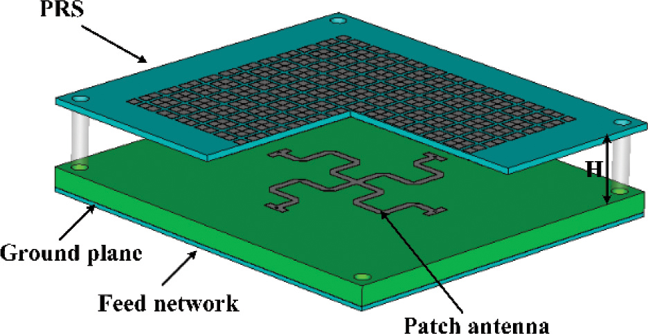
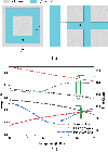
Figure 1: Structure of tri-polarization reconfigurable antenna.
2 POLARIZATION RECONFIGURABLE FP ANTENNA
Figure 1 shows the overall structure of the proposed tri-polarization reconfigurable antenna with broadband and gain enhancement. The proposed antenna consists of the following parts: feeding network, metal ground, radiation patch and PRS layer. The distance H between the PRS layer and the metal ground of the antenna is about 10mm. A PRS array is composed of 1112 periodic units as the PRS layer to increase the antenna gain. The PRS layer and the feeding antenna are connected by four M2 nylon bolts, so the overall size of the proposed antenna is 45mm50mm10mm (2.12.30.46 at 14 GHz). The radiation part is composed of a four-arm meandering line structure. Its four arms are connected to a rotating feeding network at the bottom. The PIN diodes are integrated on the rotating feeding network, and the radiation mode can be changed by controlling the state of the PIN diodes.
2.1 Design of PRS
The PRS has high reflection characteristics and can be regarded as a reflective surface, which can be loaded on top of the antenna as a cladding to form a Fabry-Perot resonant cavity, and the antenna ground serves as the lower reflective surface. In the resonant state, the electromagnetic wave generated by the feed is reflected in the cavity for many times, and the same phase is superimposed on the PRS, thereby realizing the characteristics of high-gain unidirectional radiation. However, the PRS needs to meet the following conditions to achieve broadband gain improvement:
| (1) |
where and represent the reflection phase of PRS and metal floor respectively. H is the distance between them, and is the operating wavelength of the antenna. It can be seen from (1) that the reflective phase of the PRS needs to be positively correlated with the frequency. That is to say, in order to realize the high-gain FP antenna operating in broadband, the reflective phase of the PRS should increase linearly with the increase of frequency while maintaining the high reflective coefficient of the PRS.
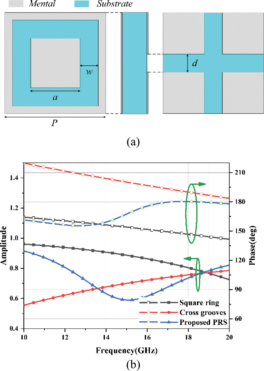
Figure 2: (a) Structure of the proposed PRS unit. (b) Reflection amplitude and phase comparison of the proposed PRS unit and the single-sided structure.
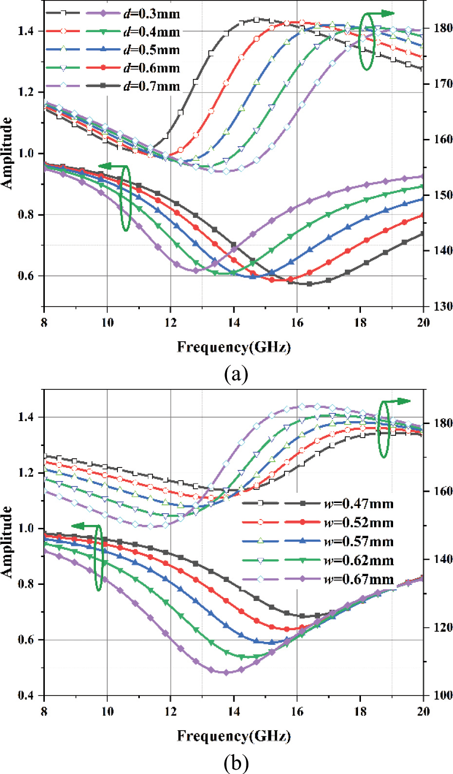
Figure 3: Influence of unit size (a) parameter d, (b) parameter w on reflection characteristics.
The PRS designed in this paper can well satisfy the resonant condition. The proposed PRS is composed of metal patches with etched square ring and cross groove as shown in Fig. 2 (a). The structure is printed on F4B dielectric material with a thickness of 0.933mm, dielectric constant of 3.0, and loss tangent (tan ) of 0.001. The dimensions of the proposed PRS unit operating in the Ku-band as follows: P=3.14mm, a=1.7mm, w= 0.63mm, d= 0.66mm. In order to better explain the proposed PRS based on positive phase gradient, the single-sided cross groove and single-sided square ring structures are simulated respectively. It can be seen from Fig. 2 (b) that the reflection coefficient of the square ring structure decreases with the increase of frequency, that is, it reflects low frequency electromagnetic waves and transmits high frequency electromagnetic waves. On the contrary, the reflection coefficient of the single-sided cross groove structure increases with the increase of frequency, so it reflects high frequency electromagnetic waves and transmits low frequency electromagnetic waves. Therefore, the combination of the single-sided square ring structure and cross groove structure can achieve partial reflection characteristics. The reflection phase is positively correlated with frequency while achieving the high reflection coefficient.
In order to further understand the reflection characteristics of the unit, the effects of parameters w and don the unit are investigated, as shown in Fig. 3. The center frequency of unit resonance shifts to high frequency with the increase of parameter d, which can be attributed to the decrease of capacitance between metal patches. In addition, with the increase of w, the reflection amplitude of PRS unit decreases and the reflection phase slope increases. Therefore, the resonant frequency can be adjusted without changing the structural period by adjusting parameter d, and the ideal wideband reflection phase curve positively correlated with frequency can be obtained by adjusting parameter w.
2.2 Feeding Network and Radiation Structure
Figure 4 show the structure of the tri-polarization reconfigurable feeding antenna. Figure 4 (a) shows the meandering curve structure etched on the front of F4BM with a thickness of 2.44mm, dielectric constant of 2.2, and loss tangent (tan ) of 0.0015. The metal ground is printed on the back of the F4BM. In order to realize the circular polarization of the antenna, it is necessary to design a four-channel output rotating feeding network with equal amplitude and 90 phase difference. Figure 4 (b) shows that the feeding network is printed on Rogers 3003 dielectric material with thickness of 0.508mm, dielectric constant of 3.0 and loss tangent (tan ) of 0.001. The rotating feeding network is mainly designed based on the idea of cascading power dividers and phase shifters. By designing power divider, inverter and 90 phase shifter, the four output ports can achieve the characteristics of equal signal amplitude and 90 phase difference.
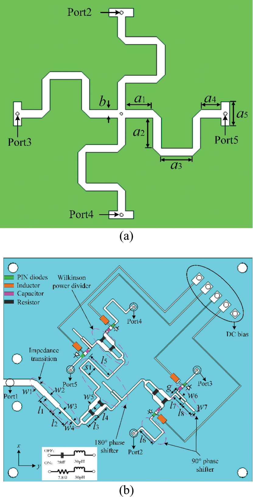
Figure 4: Structure of the proposed antenna. (a) Radiation structure of meandering curves. (b) Configurations of the feeding network and equivalent circuit of the PIN diode. The dimensions of the feeding network are given as follows (unit: mm): a=3.35, a=3.8, a=3.8, a=2.5, a=3, b=3.8, l=3.53, l=3.53, l=2.39, l=2.87, l=5.26, l=3.56, l=2.4, l=2.65, w=1.28, w=1, w=0.58, w=0.4, w=0.94, w=0.36, w=0.41, S=2, g=0.12.
Figure 4 (b) shows the detailed parameters of the feeding network. Since the proposed antenna needs to operate in broadband, it is necessary to design a broadband feeding network. There are two main reasons why the feeding network can operate in broadband. First, the two-stage Wilkinson power divider is different from the traditional Wilkinson power divider. The power divider in this paper belongs to the dual-band coupled-line divider and there are two resonant points to achieve the broadband. Second, the 90 and 180 phase shifters consist of weak coupled line and short-circuited line, which can also operate in broadband. The working mechanism of Wilkinson power divider and phase shifter can be explained by the odd-and even-mode theory[17–18].
In order to obtain the reconfigurable polarization of the antenna, some lumped elements are integrated on the feeding network, and the polarization state of radiation wave can be changed by controlling the ON/OFF states of four PIN diodes (MACOM MADP-000907-14020). The forward bias state of PIN diode can be equivalent to the series of resistor and inductor, and the reverse bias state can be equivalent to the series of capacitor and inductor, as shown in Fig. 4 (b). Through changing the states of PIN diodes, it is possible to control whether the four-arms of the antenna operate or not. When PIN1 and PIN3 are forward biased and PIN2 and PIN4 are reverse biased, the proposed antenna works in horizontal polarization state. When PIN1 and PIN3 are reverse biased and PIN2 and PIN4 are forward biased, the proposed antenna operates in vertical polarization state. If all PIN diodes are forward biased, the proposed antenna operates in a circularly polarized state.
Table 1: Polarization by different states of PIN diodes
| Polarization | PIN1 | PIN2 | PIN3 | PIN4 |
| HP | ON | OFF | ON | OFF |
| VP | OFF | ON | OFF | ON |
| RHCP | ON | ON | ON | ON |
The ON/OFF states of PIN diodes need to be controlled by a DC voltage, so the DC bias circuit is designed in the feeding network. The DC bias line and the microstrip feed-line are connected by the high-frequency inductance, which not only realizes the control of the PIN diodes, but also achieves the purpose of isolating the RF signal and the DC signal. The DC signal forms a loop through the ground via in the center of the radiating structure. The function of the capacitors is mainly to avoid the influence of DC voltage on the RF signal and to enhance the isolation of AC/DC. The absorption resistances used on the Wilkinson power divider are 91 and 300, respectively.
Since the performance of the proposed antenna depends on the performance of the feeding network, a full-wave electromagnetic simulation analysis of the rotating feeding network is performed separately. Figure 5 shows the S-parameters and phase difference curves of each port of the proposed rotating feeding network. It can be observed that the amplitudes of the four output ports are roughly equal and the phase difference is about 90. The simulation results show that the performance of the feeding network can meet the requirements of the circular polarization antenna.
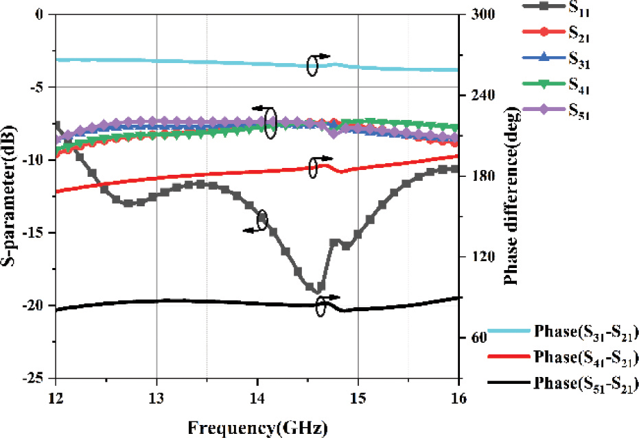
Figure 5: Simulated results of rotating feeding network.
3 SIMULATION AND MEASUREMENT PERFORMANCE
In order to verify whether the simulation results of the tri-polarization reconfigurable FP antenna are consistent with the actual measurement results, a the PRS layer and feeding antenna are fabricated based on the above structural parameters. Figure 6 shows the produced antenna prototype and the test environment in an anechoic chamber. The S-parameter, realized gain and axial ratio of the prototype antenna were measured in the anechoic chamber.
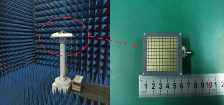
Figure 6: Photograph of the proposed antenna and test environment.
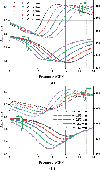
The reflection coefficient, axial ratio, realized gain and radiation pattern of the proposed antenna were measured [19]. Figure 7 shows the simulated and measured S-parameter, realized gain and axial ratio of the RHCP for the proposed antenna. Figure 7 (a) shows that the simulated and measured -10 dB impedance bandwidth is about 11% (12.5-14 GHz) and the peak realized gain is about 9.1 dBi for HP state. The measured S-parameter and realized gain of VP are depicted in Fig. 7 (b). It is observed that the measured impedance BW of S11-10 dBf is about 6.4% (13.7-14.6 GHz) and the peak realized gain is about 9.2 dBi. The reflection coefficient and realized gain of RHCP state are presented in Fig. 7 (c), and it can be observed that the measured impedance BW of S11 -10 dB is about 20% (12.2-14.9 GHz) and the peak realized gain is about 11.5 dBic. Figure 7 (d) describes the AR performance of the RHCP state. It can be found that the 3dB AR bandwidth is about 17% (12.35-13.4 GHz and 13.6-14.9 GHz).
The results show that the measured reflection coefficient of the proposed antenna is basically consistent with the simulation results. The gain and AR performance of measurement and simulation are different to some extent. The main reason for this difference may be that the equivalent circuit of the PIN diode is different from the actual parameters, which causes more loss. In addition, errors generated during antenna fabricating and testing are also included.
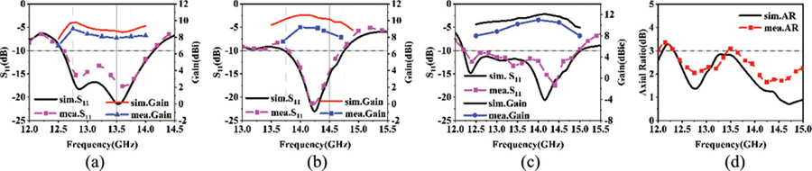
Figure 7: Simulated and measured performance of the proposed antenna. (a) Reflection coefficients and gain under HP. (b) Reflection coefficients and gain under VP. (c) Reflection coefficients and gain under RHCP. (d) AR under RHCP.
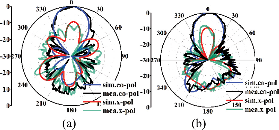
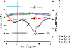
Figure 8: Simulated and measured normalized radiation patterns of HP at 12.7 GHz. (a) H-plane. (b) E-plane.
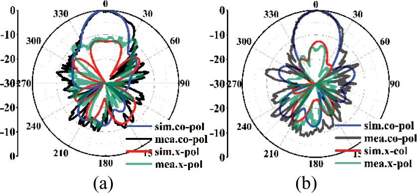
Figure 9: Simulated and measured normalized radiation patterns of VP at 14 GHz. (a) H-plane. (b) E-plane.
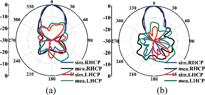
Figure 10: Simulated and measured normalized radiation patterns of RHCP at 14.4 GHz. (a) H-plane. (b) E-plane.
Simulated and measured normalized radiation patterns are compared at 12.7, 14 and 14.4 GHz for the HP, VP and RHCP modes shown in Figs. 8, 9 and 10, respectively. It is observed from Figs. 8 and 9 that for linearly polarized waves, similar pencil-beam patterns can be obtained on both sides. Due to the meandering curve structure, the instability of lumped elements integrated in the feeding network and the coupling between microstrip lines, the cross-polarization performance under HP and VP is worse than that of the RHCP. Overall, the radiation patterns of the proposed antenna remain relatively stable in the operating frequency band.
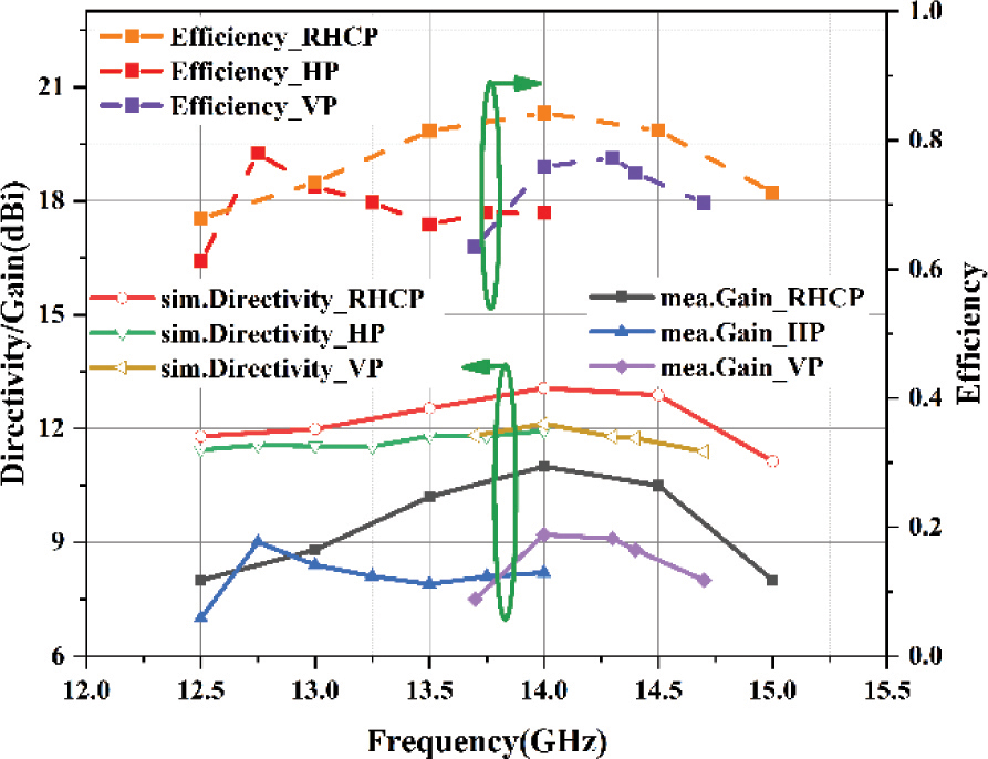
Figure 11: Measured efficiency of the proposed antenna.
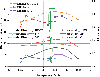
Due to the limitation of the measurement system, the 3D far-field radiation pattern of the antenna prototype cannot be obtained to calculate its directivity. Here, the measured efficiency is obtained by the ratio of the measured gain to the simulated directivity [20], as shown in Fig. 11. The efficiency of the antenna is more than 60% in the three polarization states. The loss of antenna is mainly due to DC bias circuit, PIN diodes and poor match. The loss is studied by replacing the PIN diode with metal strip and removing the DC bias circuit. Investigation shows that the loss of DC bias circuit is about 1.5 dB and the loss of the PIN diodes is about 0.3 dB. Other losses are due to poor match. Therefore, the efficiency of the antenna can be further improved by optimizing the DC bias circuit.
Table 2: Performance comparison with previously reported polarization reconfigurable antennas
| Ref. | [4] | [6] | [13] | This work |
| Freq. (GHz) | 2.4 | 5 | 7.4 | 14 |
| Size () | - | 1.81.8 0.5 | 220.6 | 2.12.3 0.46 |
| Polarization | 3 | 3 | 3 | 3 |
| Feeding network | No | Yes | Yes | Yes |
| AR BW(%) | 7.9 | 13.1 | 4 | 17 |
| No. of switches | 4 | 8 | 2 | 4 |
| Gain(dBi) | 9 | 11.2 | 15.1 | 11.5 |
Table 2 presents a comparison among the proposed antenna and the reported reconfigurable antenna. It can be noted that the proposed antenna shows the advantages in high gain and wide BW.
4 CONCLUSION
In this paper, gain enhancement for wideband tri-polarization reconfigurable FP antenna is realized by loading a metallic PRS layer. The designed single-layer PRS achieves a good performance with a positive gradient of the reflection phase in broadband, and can well improve the gain of the proposed antenna. Three polarization states, including HP, VP and RHCP states, have been realized using four PIN diodes integrated into the feeding network. The measured results have confirmed that the antenna is able to achieve 10 dB bandwidth of 11%, 6.4% and 20% for HP, VP and RHCP, and the peak realized gain achieved 9.1, 9.2 and 11.5 dBi, respectively. For RHCP mode, the 3 dB axial ratio bandwidth of about 17% is achieved. The simulation and measurement results show that the radiation patterns of E-plane and H-plane in the tri-polarization states of the antenna are similar and symmetrical, with good directivity. In addition, the DC bias circuit that controls the state of the PIN diodes can be easily integrated into the rotating feeding network. The proposed antenna is suitable for polarization diversity applications.
REFERENCES
[1] J. Row and Y. Wei, “Wideband reconfigurable crossed-dipole antenna with quad-polarization diversity,” IEEE Transactions on Antennas and Propagation, vol. 66, no. 4, pp. 2090-2094, 2018.
[2] H. Sun and Z. Pan, “Design of a quad-polarization-agile antenna using a switchable impedance converter,” IEEE Antennas and Wireless Propagation Letters, vol. 18, no. 2, pp. 269-273, 2019.
[3] K. M. Mak, H. W. Lai, K. M. Luk, and K. L. Ho, “Polarization reconfigurable circular patch antenna with a C-shaped,” IEEE Transactions on Antennas and Propagation, vol. 65, no. 3, pp. 1388-1392, 2017.
[4] F. Wu and K. M. Luk, “Wideband tri-polarization reconfigurable magneto-electric dipole antenna,” IEEE Transactions on Antennas and Propagation, vol. 65, no. 4, pp. 1633-1641, 2017.
[5] H. H. Tran, N. Nguyen-Trong, T. T. Le, and H. C. Park, “Wideband and multipolarization reconfigurable crossed bowtie dipole antenna,” IEEE Transactions on Antennas and Propagation, vol. 65, no. 12, pp. 6968-6975, 2017.
[6] L. Ji, P. Qin, Y. J. Guo, C. Ding, G. Fu, and S. Gong, “A wideband polarization reconfigurable antenna with partially reflective surface,” IEEE Transactions on Antennas and Propagation, vol. 64, no. 10, pp. 4534-4538, 2016.
[7] J. Hu, Z. Hao, and W. Hong, “Design of a wideband quad-polarization reconfigurable patch antenna array using a stacked structure,” IEEE Transactions on Antennas and Propagation, vol. 65, no. 6, pp. 3014-3023, 2017.
[8] J. A. Ganie and K. Saurav, “High gain polarization reconfigurable antenna arrays using a polarization reconfigurable converter,” International Journal of RF and Microwave Computer-Aided Engineering, p. e22765, 2021.
[9] P. Qin, L. Ji, S. Chen, and Y. J. Guo, “Dual-polarized wideband fabry–perot antenna with quad-layer partially reflective surface,” IEEE Antennas and Wireless Propagation Letters, vol. 17, no. 4, pp. 551-554, 2018.
[10] W. Li, S. Gao, Y. Cai, Q. Luo, M. Sobhy, G. Wei, J. Xu, J. Li, C. Wu, and Z. Cheng, “Polarization-reconfigurable circularly polarized planar antenna using switchable polarizer,” IEEE Transactions on Antennas and Propagation, vol. 65, no. 9, pp. 4470-4477, 2017.
[11] M. A. Meriche, H. Attia, A. Messai, S. S. I. Mitu, and T. A. Denidni, “Directive wideband cavity antenna with single-layer meta-superstrate,” IEEE Antennas and Wireless Propagation Letters, vol. 18, no. 9, pp. 1771-1774, 2019.
[12] W. Cao, X. Lv, Q. Wang, Y. Zhao, and X. Yang, “Wideband circularly polarized fabry–perot resonator antenna in Ku-band,” IEEE Antennas and Wireless Propagation Letters, vol. 18, no. 4, pp. 586-590, 2019.
[13] H. H. Tran and H. C. Park, “A simple design of polarization reconfigurable fabry-perot resonator antenna,” IEEE Access, vol. 8, pp. 91837-91842, 2020.
[14] J. Ren, W. Jiang, K. Zhang, and S. Gong, “A high-gain circularly polarized fabry–perot antenna with wideband low-RCS property,” IEEE Antennas and Wireless Propagation Letters, vol. 17, no. 5, pp. 853-856, 2018.
[15] R. Lian, Z. Tang, and Y. Yin, “Design of a broadband polarization-reconfigurable fabry–perot resonator antenna,” IEEE Antennas and Wireless Propagation Letters, vol. 17, no. 1, pp. 122-125, 2018.
[16] K. Gao, X. Ding, L. Gu, Y. Zhao, and Z. Nie, “A broadband dual circularly polarized shared-aperture antenna array using characteristic mode analysis for 5G applications,” International Journal of RF and Microwave Computer-Aided Engineering, vol. 31, no. 3, p. e22539, 2021.
[17] Q. Liu, H. Liu, and Y. Liu, “Compact ultra-wideband 90 phase shifter using short-circuited stub and weak coupled line,” Electronics Letters, vol. 50, no. 20, pp. 1454-1456, 2014.
[18] Y. Wu, Y. Liu, and Q. Xue, “An analytical approach for a novel coupled-line dual-band Wilkinson power divider,” IEEE Transactions on Microwave Theory and Techniques, vol. 59, no. 2, pp. 286-294, 2011.
[19] B. Y. Toh, R. Cahill, and V. F. Fusco, “Understanding and measuring circular polarization,” IEEE Transactions on Education, vol. 46, no. 3, pp. 313-318, 2003.
[20] J. Hu and Z. C. Hao, “A compact polarization-reconfigurable and 2-D beam-switchable antenna using the spatial phase shift technique,” IEEE Transactions on Antennas and Propagation, vol. 66, no. 10, pp. 4986-4995, 2018.
BIOGRAPHIES

Shichao Zhu received the Bachelor degree in School of Electrical and Automation Engineering from East China Jiaotong University, Nanchang, China in 2020. He is currently pursuing the Master degree in the College of Electrical and Information Engineering, Hunan University, Changsha China, under the supervision of Prof. G.S. Li. His research interests include reconfigurable antennas, electromagnetic metamaterials and their antenna applications.

Jiagang Heb was born in Xiangtan, Hunan province, China, in 1997. He received the Bachelor degree in College of electronic science and technology from Hunan University of Technology, Zhuzhou, China, in 2019. He is now studying for postgraduate in the College of electronic science and technology, Hunan University. His research interests is terminal antenna and EMC.

Jie Yu was born in Xinyang, Henan province, China, in 1998. He received the Bachelor degree in optoelectronic information science and engineering from Changsha University of Science and Technology, Changsha, China, in 2019. He is currently working as postgraduate in Hunan University. His research interest is the liquid antennas.

Yang Feng was born in Yongzhou, Hunan province, China, in 1997. He received the Bachelor degree in Communication Engineering from Beijing Union University, Beijing, China, in 2019. He received the Master degree in Electronics and Communication Engineering from Hunan University, Changsha, China, in 2022. His research interests are in antenna theory and technology, including implantable antenna technology, antenna miniaturization technology.

Shaopeng Pan received the Bachelor degree in School of Physics and Electronic Science, Hunan University of Science and Technology (HNUST), Xiangtan, China, in 2019. He received the Master degree in Electronic Science and Technology form Hunan University (HNU), Changsha, China in 2022. His research interests include holographic antenna technology, electromagnetic metamaterials and programmable metamaterial antenna.

Gaosheng Li received his B.S. degree in electromagnetic field and microwave and his M.S. degree as well as his PH. D. in electronic science and technology from the National University of Defense Technology (NUDT), Changsha, China, in 2002, 2004 and 2013, respectively. He was with NUDT as a Teaching Assistant from 2004 to 2006, a Lecturer from 2006 to 2011, and then as an Associate Professor from 2011 to 2017. He joined Hunan University as a Professor in 2018. From 2014 to 2016, he was with Nanjing University of Aeronautics and Astronautics (NUAA) and Wuxi Huace Electronic Systems Co., Ltd., China as a Postdoctoral Research Fellow. From 2016 to 2017, he was a Visiting Scholar at the University of Liverpool (UoL), United Kingdom, sponsored by China Scholarship Council (CSC). His research interests include Antennas and Propagation (AP), Electromagnetic Compatibility (EMC), Wireless Propagation and Microwave Systems. Prof. Li is the author or co-author of 8 books and 170 papers published in journals and conference proceedings. He owns 3 international patents, 45 Chinese patents and 14 software copyrights. He won 3 national scientific prizes in 2008, 2013 and 2015, respectively. He is now a Senior Member of IEEE (2019), a Member of ACES (2017) and IEICE (2011), a Senior Member of Chinese Institute of Electronics (CIE, 2014), China Institute of Communications (CIC, 2017) and China Instrument and Control Society (CIS, 2020).
ACES JOURNAL, Vol. 37, No. 8, 848–855.
doi: 10.13052/2022.ACES.J.370803
© 2022 River Publishers