Synthesis of Elliptical Antenna Array using Hybrid SSWOA Algorithm
D. Prabhakar, K. Srinivas, S. Ratna Spandana, D. Anusha, M. V. Srikanth, and Y. Rama Krishna
Department of ECE
Seshadri Rao Gudlavalleru Engineering College (A), Seshadri Rao Knowledge Village, Gudlavalleru
Andhra Pradesh, 521356 India
prabhakar.dudla@gmail.com, yrk.gec@gmail.com
Department of AI & DS
Seshadri Rao Gudlavalleru Engineering College (A), Seshadri Rao Knowledge Village, Gudlavalleru
Andhra Pradesh, 521356 India
kalyanapusrinivascse@gmail.com
Department of ECE
Vijaya Institute of Technology for Women, Vijayawada, Andhra Pradesh, 521108 India
spandana.suriteti@gmail.com
Department of E & I
V.R. Siddhartha Engineering College, Vijayawada, Andhra Pradesh, 520007 India
dasarianusha405@gmail.com
Department of ECE
Usha Rama College of Engineering and Technology, Telaprolu, Andhra Pradesh, 521109 India
sree.02476@gmail.com
Submitted On: February 3, 2022; Accepted On: May 30, 2023
ABSTRACT
In terms of research, the elliptical antenna arrays (EAA) synthesis is relatively novel. As it does not have to be circular in construction, this novel synthesis can maneuver the primary beam in the right direction, making it easier to realize. The amplitude and angular location of the ellipse, as well as the eccentricity of the ellipse, are all taken into account in the optimization process. The proposed hybrid algorithm is the SSWOA (Salp Swarm Whale Optimization Algorithm), which combines the Salp Swarm Optimization Algorithm (SSA) with the Whale Optimization Algorithm (WOA). The SSA algorithm serves as a guide, while the WOA algorithm serves as a helper in this method. We discover that optimization has a faster convergence time and high convergence accuracy when considering the benefits of SSA and WOA and applying them to the synthesis of antenna array layouts. If Griewank, Rosenbrock, Sphere, and Rastrigin test functions are used, it’s worth noting that the hybrid method outperforms both WOA and SSA.
Index Terms: elliptical antenna array (EAA), Griewank, pattern synthesis, speed of convergence, sphere, rastrigin, Rosenbrock.
I. INTRODUCTION
The single antenna structure of antenna arrays gives it a great advantage in its wide usage, especiallyin defence applications, for example, sonar, radar, communication, and navigation systems. Higher levels of gain and directivity can be provided by these antenna arrays. Generally, the antenna arrays are categorized based on geometrical differences. Concentric circular, planar, linear, and circular, besides elliptical arrays, can be cited as specimens of these clusters. Nevertheless, in their research area, elliptical antenna arrays are comparatively novel [1–6]. Various means are adapted to synthesize the elliptical antenna arrays. The majority of this work is focused on linear and circular antenna arrays. Nevertheless, it is a widely known fact that elliptical antenna arrays possess radiation properties just like that of circular antenna arrays. The entire space is occupied by the elliptical antenna arrays because of their radiation pattern; furthermore, the primary beam of the array can be changed to the desired direction. Linear antenna, rectangular arrays, and elliptical antenna arrays should not be coupled together as the latter is less sensitive. This is because they lack the edge elements [7–8]. The elliptical antenna array (EAA) synthesis is the combination of the position only, the amplitude only, or amplitude position techniques. Of these, the most used technique is the position only technique. In these three distinct algorithms namely the SADE, i.e., self-adaptive differential evolution, the BBO, i.e. Biogeography-Based Optimization, in addition to Firefly algorithms (FA),[4] are used to identify the optimal position of elements on the ellipse circumference which has the capacity of bringing down the maximum side lobe level (SLL) with fixed Beam Width between First Nulls (BWFN). The amplitude technique is explored by making use of the non-uniform current distribution, where the element position is stationary and cannot be changed. Further, by comparing BSA with BBO, FA, genetic algorithm (GA), and differential evolution(DE) the performance of thealgorithm is evaluated.
In this paper, EAA radiation synthesis is designed using a hybrid algorithm of SSWOA. The SSA, i.e., Salp Swarm Optimization combined with WOA, i.e., Whale Optimization Algorithm is a newly suggested algorithm. In this algorithm, the SSA algorithm acts as a guide while the WOA algorithm serves the role of an aid. With the aim of preventing a premature convergence and exploring wholly the problem of hyperspace, the leader updating the neighbour’s best point is measured. Likewise, after the salps point updating, by employing WOA to improve the optimum searchability, the well-known point hasevolved. A combination of these algorithms enhances the diversity of the offspring,as well as maintaining the search-balance.
This paper is organized as follows:The presentation of the radiation synthesis model employing a hybrid algorithm of SSWOA for EAA is dealt with in section II. In section III the comparisons and numerical experiments on the EAA pattern synthesis are illustrated. Section IV offers the concluding section of this paper.
II. METHODOLOGYPROPOSED
This section proposes the hybrid algorithm of SSWOA for radiation pattern synthesis of the EAA. The algorithm of SSWOA being proposed is a blend of WOA as well as SSA. In this, the SSA algorithm effectually guides the evolution, while the WOA algorithm serves as the assistant’s role. With a view to averting an untimely convergence and with the view to fully exploring the problem in hyperspace, the leader updating the best position is wellthoughtout. A unique function is used to govern the algorithm proposed as a continuation of the above. An elaborative procedure of the algorithm being proposed is clearly explained in thefollowing subsection.
A. The SSWOA algorithm
The SSWOA method is described and used in this part to create patterns for elliptical antenna arrays. It is thought of as a global optimization problem,
| (1) |
where the number of optimized variables denoted as is the higher bound and is the lower bound of respectively.
As suggested in 2017 by Mirjalili [9], SSA is a new type of algorithm for resolving single-objective as well as multi-issues. The main motivation for the SSA is the swarming behaviour of salps when voyaging or foraging in the oceans. Finally, this SSA produces accurate and the best possible or even near-optimal arrangements in the optimization process. Particularly in this investigation, to give the optimal result competently, the investigative behaviour of SSA is increased by WOA [10–11]. The WOA is a natural and meta-heuristic optimization algorithm, which is deduced from characteristics of humpback whales. The following steps delineate the complete process of the hybrid algorithm suggested.
Stage 1: Initiating
In the initial stage of the SSA, the places of the salps are arbitrarily instated in the dimensional space which is communicated as,
| (2) |
Stage 2: Appraisal
In this step, the suitability of each explore agent is appraised. The subsequent equation provides the vital objective function,
| (3) |
Stage 3: The procedure of search employing
Layer 1: Explorative Stage (searching for quarry)
In the Explorative Stage, the location of a search agent gets modernized.
| (4) |
| (5) |
The probing extract in equations (4) and (5) and by the shrinking system the encompassing quarry in equations (6) and (7) are employed if .
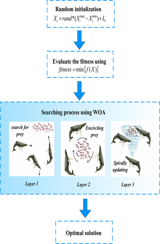
Figure 1: Steps of proposed SSWOA algorithm.
Layer 2: Encompassing quarry
To discover an optimal solution proficiently, the probing performance of the SSA is boosted by the WOA, by the subsequent equation.
| (6) | |||
| (7) |
where, and are considered as vector coefficients, and I as current iteration, the finest value of location vector up to now is symbolized like and denotes the location vector.
The vector coefficients and are expressed as,
| (8) | ||||
| (9) |
At this juncture, the random numeral in the middle of [0, 1] is specified like R and the changeable A is linearly diminishing as of [2-0].
Layer 3: Location apprising
The updating spiral location is represented as,
| (10) |
where the constant for portraying the spiral shape has been designated as h, the random numeral between [0, 1] is designated as P and l is [-1, 1].
Step 4: Termination procedure
When the procedure is accomplished, the projected technique chooses the optimum result or as well comes flip side to step 2. Figure 1 displays the steps of the projected hybrid algorithm of SSWOA. Thus, the grouping of SSA and WOA algorithms improves the variety of the progeny. Likewise, the desired search ability of the algorithm is heightened.
B. Elliptical antenna array (EAA) pattern synthesis array factor formulation
In this subsection, the geometry of EAA and the corresponding AF are explored, leading to array optimization in the following subsections. The EAA is a kind of antenna array in which the elements of the antenna are placed at the boundary of an ellipse. Figure 2 illustrates an instance of N-element EAA lying in the x-y plane and has its midpoint positioned at the origin [12].
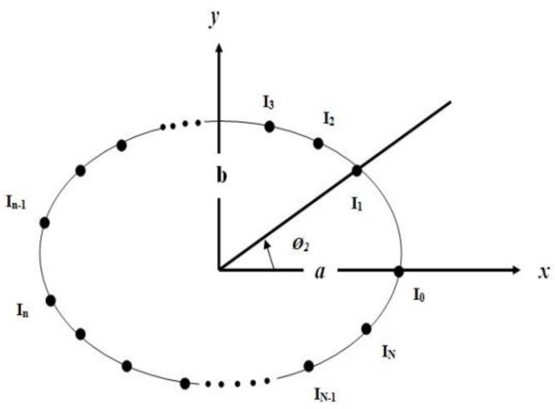
Figure 2: N-element EAA.
Array factor for the EAA portrayed in Fig. 2 is given by:
| (11) | ||||
Where:
a is the semi-major axis of the ellipse
b is the semi-minor axis of the ellipse
is excitation amplitude of n element
k=2/ (wave number)
is Elevation angle
is angular position of the n element,
Ø is azimuth angle
is excitation phase of the n element
| (12) |
The eccentricity (e) of the ellipse is,
| (13) |
If the e lies between 0 and 1, when e is ‘0’ then e becomes a circle, when e is ‘1’, then it becomes a line.
C. Radiation pattern synthesis using hybrid algorithm of SSWOA
Here, the radiation pattern synthesis of the array is discussed in detail to show the suggested hybrid algorithm. The array pattern is obtained through the superposition rule, where the radiation pattern of all active elements is extracted and stored. Several sub-goals put together are the primary objectives of the antenna array design to insert various objectives into one fitness function. This fitness function may be defined as,
| (14) |
At this point,
| (15) | |||||
| (16) | |||||
| (17) | |||||
| (18) | |||||
| (19) | |||||
| (20) |
The subsequent section displays the efficacy of the algorithm proposed with some numerical experimentation.
III. NUMERICAL RESULTS AND DISCUSSION
In this part, the adequacy of the projected calculation is checked to employ certain test capacities. At this point, we utilized four test capacities and these are utilized as central capacities for advancement techniques like the SSA besides the WOA. The capacities are clarified as follows,
| (21) | |||
| (22) | |||
| (23) | |||
| (24) |
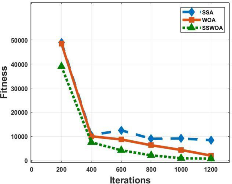
Figure 3: The sphere function’s average fitness value by way of diverse algorithms.
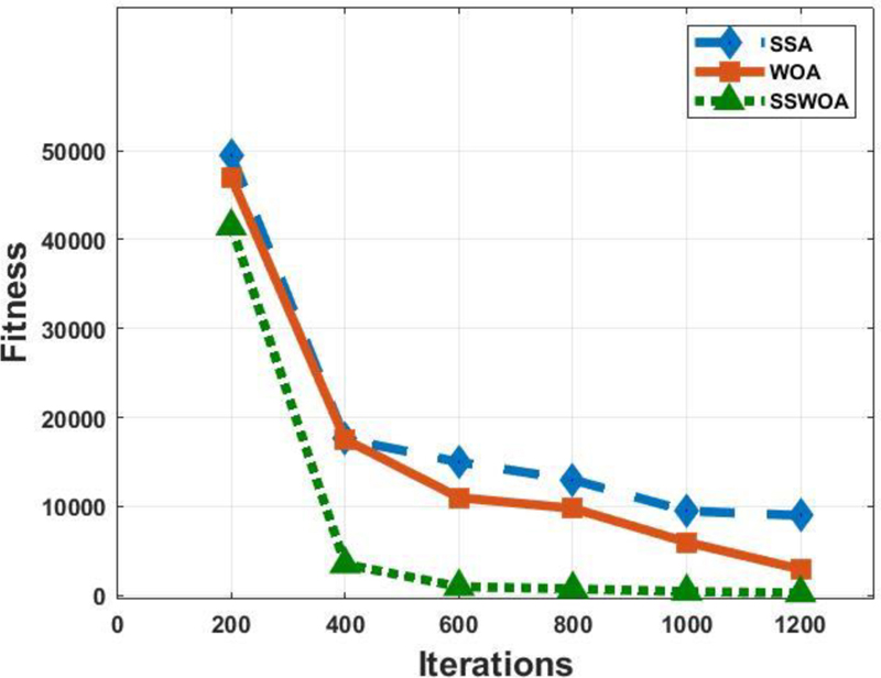
Figure 4: The Griewank function’s average fitness value employing diverse algorithms.
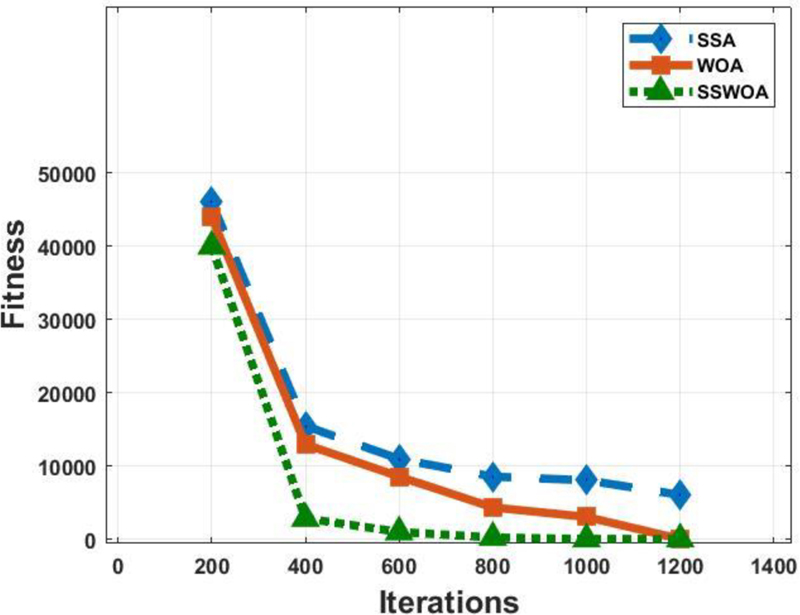
Figure 5: The Rosenbrock function and its average fitness value employing several algorithms.
For comparison, SSA, WOA and SSWOA are simulated by utilizing the mentioned four test functions in 3D dimensions. The fitness or cost estimation of the result is characterized as the calculated F(X). The deviation curve of the cost value employing several iterations is revealed in Figs. 3–6.
For these algorithms, the population size is alike. Employing different kinds of algorithms, the average fitness value of the sphere function is revealed in Fig. 3. The cost values of the SSA, WOA, and SSWOA algorithms steadily decrease by employing raising iterations. As per the illustration, it can be detected and designed that hybrid SSWOA algorithm is better at 20.408%, 28.57%, 66.39%, 76.65%, 90.1%, 91.65% when compared with standard SSA and 19.58%, 24.99%, 66.39%, 76.65%, 99.01%, 91.65% when compared with standard WOA with the number of iterations.
The Griewank function’s average fitness value with many iterations is illustrated in Fig. 4. It is understood from Fig. 4 that, when compared with standard SSA, the suggested hybrid method has lower fitness of 16.16%, 80.00%, 93.32%, 94.22%, 99.52%, 96.83%. While compared with WOA, the adopted hybrid method has lower fitness of 11.70%, 79.93%, 90.9%, 92.34%, 92.48%, and 90.34% with rising iteration. The simulated results show that the suggested hybrid method is superior to the single algorithm and has a much better balance between exploitation and exploration ability.
The Rosenbrock function’s average fitness value is displayed in Fig. 5 by making use of many algorithms. The projected technique has a healthier fitness value of 13.04%, 81.28%, 90.44%, 99.6%, 98.87%, 98.53% and 9.09%, 77.69%, 87.78%, 93.16%, 97.06%, 1.10% as compared with standard SSA and WOA. Figure 6 shows the average fitness value of the Rastrigin function. While we compare it by standard SSA and WOA, the suggested method evinces superior fitness value of 41.49%, 45.16%, 58.16%, 73.14%, 94.09%, 91.68% and 37.94%, 40.48%, 55.99%, 69.68%, 93.135%,89.14%.
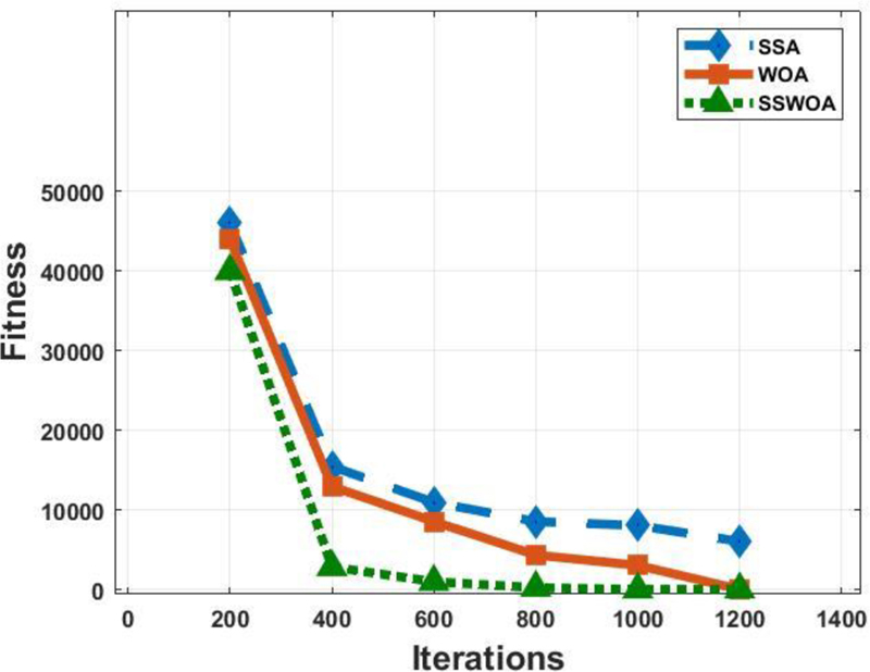
Figure 6: Rastrigin function and itsaverage fitness value utilizing several algorithms.
Figure 7 illustrates the antenna’s gain curve across various frequencies when employing different algorithms. Meanwhile, Fig. 8 showcases the reflection coefficient s under diverse phase angles, each assessed through various algorithms. Based on these graphical representations, it becomes evident that the proposed hybrid algorithm outperforms both SSA and WOA.
From the obtained results, it is clearly shown that the hybrid algorithm proposed has more energetic investigating capability and quicker convergence speed when it is compared with the standard of the SSA or the WOA. Figures 9 and 10 clearly show how the excitation amplitude and phase of the element are obtained byusing SSWOA.
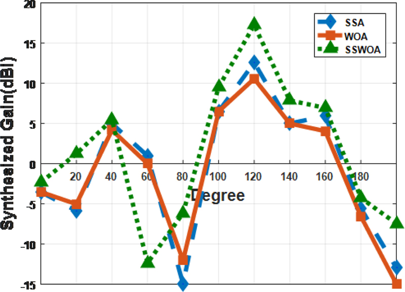
Figure 7: The performance comparisons of the pattern of gain utilizing diverse algorithms.
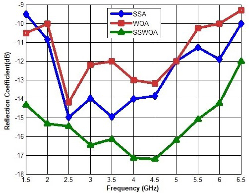
Figure 8: The performance comparisons of the reflection coefficient S (dB) utilizing diverse algorithms.
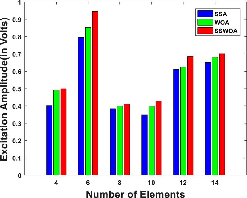
Figure 9: Amplitude excitation using SSWOA.
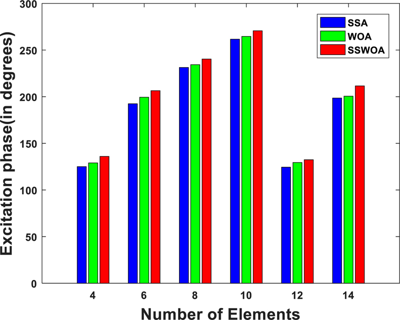
Figure 10: Phase excitation using SSWOA.
Table 1: Comparison table from existing works
| Author | Algorithms | Iterations | Fitness | Angle |
| Sharaqa and Dib [4] | Self-Adaptive Differential Evolution (SADE) | 800 | NR | 300 |
| Sharaqa and Dib [4] | Biogeography-Based Optimization (BBO) | 800 | NR | 300 |
| Sharaqa and Dib [4] | Firefly Algorithm (FA) | 800 | NR | 300 |
| Guney et al. [8] | Backtracking Search (BSA) | 1400 | NR | 300 |
| Khodier [12] | Cuckoo | 300 | 10 | 300 |
| Proposed | SSWOA | 1200 | 800 | NR |
NR-Not Reported
IV. CONCLUSION
It may be stated that a hybrid SSWOA optimization algorithm can be suggested for the radiation pattern synthesis of EEA. The above-suggested method only needs simple mathematical processing. Moreover, it is effective to put into practice. In EEA pattern synthesis, the numerical results do demonstrate that the suggested algorithm is efficient and achieves the best possible design with high accuracy as well as fast convergence swiftness. Further, the results show that the suggested technique performs better when it comes to the sphere, Rastrigin, Griewank, Rosenbrock, and test functions. The method proposed clearly shows a superior excitation amplitude and phase for a varying number of elements.
REFERENCES
[1] H. Yu and C.-W. Su, “Characteristics of frequency scanning elliptical array,” IEEE Antennas and Propagation Society Symposium Digest, vol. 3, pp. 1416-1419, June 1991.
[2] A. A. Lotfi Neyestanak, M. Ghiamy, M. Naser-Moghaddasi, and R. A. Saadeghzadeh, “Investigation of hybrid elliptical antenna arrays,” IET Microwaves, Antennas & Propagation, vol. 2, no. 1, pp. 28-34, 2008.
[3] R. A. Sadeghzadeh, A. A. Lotfi Neyestanak, M. Naser-Moghadasi, and M. Ghiamy, “A comparison of various hybrid elliptical antenna arrays,” Iranian Journal of Electrical and Computer Engineering, vol. 7, no. 2, pp. 98-106, 2008.
[4] A. Sharaqa and N. Dib, “Position-only side lobe reduction of a uniformly excited elliptical antenna array using evolutionary algorithms,” IET Microwaves, Antennas & Propagation, vol. 7, no. 6, pp. 452-457, 2013.
[5] A. Samanzare, “Elliptical antenna array pattern synthesis with fixed side lobe level and suitable main lobe beam width by genetic algorithm,” Majlesi Journal of Telecommunications Devices, vol. 2, no. 1, pp. 1-8, 2013.
[6] A. Sharaqa and N. Dib, “Design of linear and elliptical antenna arrays using biogeography-based optimization,” Arabian Journal for Science and Engineering, vol. 39, no. 4, pp. 2929-2939, 2014.
[7] R. J. Mailloux, Phased Array Antenna Handbook, Artech House, Boston, London, 2017.
[8] K. Guney and A. Durmus, “Elliptical antenna array synthesis using backtracking search optimisation algorithm,” Defence Science Journal, vol. 66, no. 3, pp. 272-277, 2016.
[9] S. Mirjalili, A. H. Gandomi, S. Z. Mirjalili, and S. Saremi, “Salp Swarm Algorithm: A bio-inspired optimizer for engineering design problems,” Advances in Engineering Software, vol. 114, pp. 163-191, 2017.
[10] S. Mirjalili and A. Lewis, “The whale optimization algorithm,” Advances in Engineering Software, vol. 95, pp. 51-67, 2016.
[11] D. Prabhakar and M. Satyanarayana, “Sidelobe pattern synthesis using hybrid SSWOA algorithm for the conformal antenna array,” Engineering Science and Technology, an International Journal, vol. 22, no. 6, pp. 1169-1174, Dec. 2019.
[12] M. Khodier, “Optimization of elliptical antenna arrays using the cuckoo search algorithm,” IEEE-APS Topical Conference on Antennas and Propagation in Wireless Communications (APWC), Spain, pp. 143-147, 2019.
BIOGRAPHIES

Dudla Prabhakar completed his M.Tech. degree from Andhra University in 2003 and Ph. D. degree from Andhra University in 2017. He is currently working as an Associate Professor, in the Department of ECE, Seshadri Rao Gudlavalleru Engineering College (A), Gudlavalleru. His areas of research interest are EMI/EMC, Antenna Array Synthesis and Applied Electromagnetic applications. He has published papers in various journals/proceedings in the field of Antenna Arrays and EMI/EMC.

Kalyanapu Srinivas completed his M.Tech. and Ph.D. in Computer Science Engineering from Acharya Nagarjuna University, Guntur. Currently, he is head of department of AI&DS at Seshadri Rao Gudlavalleru Engineering College (A), Gudlavalleru. He has more than 40 publications in reputable international journals under his belt. He also has 4 patents to his credit. His areas of interest are Software Testing, Data Mining, AI, Machine Learning, Fuzzy Systems and Operating Systems.

S. Ratna Spandana completed her M.Tech. degree from JNTUK, Kakinada in 2021. She is currently working as an Assistant Professor, in the Department of ECE, Vijaya Institute of Technology for Women, Vijayawada. She is interested in the area of communication systems.

D. Anusha completed her M.Tech. in the specialization of embedded systems. She is currently working as an Assistant Professor in Velagapudi Ramakrishna Siddhartha Engineering College, Kanuru, Vijayawada. She is pursuing her Ph.D. from Puducherry Technological University, Puducherry.

M. V. Srikanth is a Research Scholar, pursuing a Ph.D. in the field of Image Processing from Jawaharlal Nehru Technological University, Kakinada, Andhra Pradesh, India. He is working as an Assistant Professor in the department of ECE, Usharama College of Engineering and Technology, Vijayawada.

Y. Ramakrishna received his Ph.D. in Smart Antennas from JNT University, Kakinada in 2015 and his Master’s Degree in Microwave Engineering from Acharya Nagarjuna University, Guntur in 2005. He is working as a Professor at Seshadri Rao Gudlavalleru Engineering College, Gudlavalleru. His research interests include microwave antennas, optical communications, mobile communications and smart antennas.
ACES JOURNAL, Vol. 38, No. 5, 309–315
doi: 10.13052/2023.ACES.J.380503
© 2023 River Publishers