Complex Inhomogeneous Dielectric Target Modeling and Scattering Estimation using a Self-Designed Software
Muyu Hou, Shuhong Gong, Yanchun Zuo, and Yu Liu
1School of Physics and Optoelectronic Engineering
Xidian University, Xi’an 710071, China
myhou2022@163.com, yczuoemail@163.com, 13649292113@163.com
2Collaborative Innovation Center of Information Sensing and Understanding
Xidian University, Xi’an 710071, China
shgong@xidian.edu.cn
Submitted On: February 23, 2022; Accepted On: May 25, 2022
Abstract
This paper presents a method to finely model the arbitrarily irregular-shaped and inhomogeneous dielectric target. The target is first geometrically divided into a set of homogeneous and isotropic tetrahedral regions. Each region is precisely matched with a set of electromagnetic parameters. As a result, this can accurately model the target which has an extremely complex dielectric constant distribution and an irregular shape. Regarding the electromagnetic scattering evaluation of the established model, the method of moments (MoM) is adopted in consideration of the coupling between these tetrahedral regions, and the total scattering is obtained by solving the matrix equation. The above two computational sections are integrated into a self-designed software. One can just input the spatial distribution of the dielectric constant and then the designed software automatically processes the target’s geometric information and meshes the target. Finally, the scattered electric field and radar cross section (RCS) of the target are output from the software. The designed software provides an effective and accurate way to study the electromagnetic scattering characteristics of the complex inhomogeneous objects.
Index Terms: Dielectric inhomogeneous target, fine geometric modeling, MoM, scattering evaluation.
I. INTRODUCTION
Inhomogeneous dielectric objects with irregular shapes are ubiquitous, and their electromagnetic scattering characteristics have enormous applications, such as the aerosol particle multi-scattering in weather radar [1], the turbulence scattering in tropospheric communication [2], and the aircraft wake scattering in anti-stealth [3]. However, the electromagnetic scattering evaluation methods in the open literature pursue calculation efficiency by reducing the complexities of the algorithm or the model. This obviously causes errors in the estimation of the scattering properties of the target. A self-designed software is released in this paper to accurately reconstruct the complex inhomogeneous targets with numbers of homogeneous tetrahedrons. Meanwhile, the corresponding scattering is calculated using the in-house code of MoM, which has been integrated into the designed software.
Regarding the modeling of inhomogeneous targets with irregular shapes, target models are often simplified. For example, in calculating the aircraft wake scattering characteristics, the radial density gradient (RDG) model is adopted to approximate the wake vortex as a dielectric cylinder [4, 5], and the adiabatic transport (AT) model regards the vortex wake as a circle whose cross-sectional radius is the function of the vortex distance [4]. All these methods reduce the complexities of calculation, but these approximations also reduce the abilities to accurately describe real scenarios. It is also reported that programming platforms can be utilized together with commercial computational software to obtain the scattering of inhomogeneous dielectric targets. In 2015, Farahbakhsh et al. proposed a MATLAB toolbox to model inhomogeneous media combined with the commercial software FEKO. Users can utilize a deterministic function of the target’s dielectric constant with relation to the spatial position, , to model the dielectric targets [6]. However, if the dielectric constant distribution cannot be explicitly expressed, the above-mentioned toolbox is no longer applicable. Moreover, it is difficult to accurately reconstruct the geometric irregular targets using small cubes (adopted in [6]), which is easy to produce large modeling errors in scattering calculation.
Regarding scattering estimation, empirical formulas are often used to calculate the scattering of complex inhomogeneous targets. For instance, in the empirical formula of turbulent scattering, the structure constant and frequency determine the radar cross section (RCS) [7, 8]. In the Ulaby empirical model, incident angle and six undetermined coefficients determine the backscattering of the terrain [9]. Empirical formulas reduce the complexities and the time cost of electromagnetic scattering calculation, but the accuracy of undetermined coefficients depends on large numbers of experimental data.
The main contributions of this work are three-fold:
For the electromagnetic scattering simulation of random media (such as the atmospheric turbulence), a spatial spectrum function and Monte Carlo simulation-based method is first proposed (to our best knowledge) in this paper to obtain the spatial distribution of dielectric constant. On this basis, one can apply existing numerical methods to analyze the electromagnetic scattering characteristics of the inhomogeneous target whose dielectric constant fluctuates in 3-D space, which is no longer solely dependent on empirical models.
To precisely reconstruct the irregular-shaped and inhomogeneous dielectric target for the electromagnetic scattering simulation, a novel method based on computer graphics and tetrahedron meshing strategy is proposed.
Integrated with the above methods and the method of moments (MoM), a user-friendly software for the electromagnetic scattering simulation of complex inhomogeneous targets is developed. This software is not only applicable for the target with a continuously varying dielectric constant, but also can handle the target whose dielectric constant is arbitrarily distributed.
The rest of this paper is organized as follows. The methodology and the designed software are introduced in detail in Section II. Methods include obtaining the dielectric constant spatial distribution according to a deterministic formula or a spatial spectrum function, modeling the irregular-shaped and inhomogeneous dielectric target with tetrahedron elements, and estimating electromagnetic scattering by MoM. In Section III, simulations are performed to test the designed software. Section VI concludes this paper.
II. METHODOLOGY AND SOFTWARE DESIGN
This section discusses the corresponding methods, which are involved in modeling and electromagnetic scattering calculation of complex inhomogeneous dielectric targets, and the software developed based on these methods. Specifically, the designed software provides two separated data processing channels, say Channel-A and Channel-B. For Channel-A, the input is the point cloud data of the dielectric constant. Then, this information is used to reconstruct the profile of the target. Following this, meshing and simulation modeling are carried out. The electromagnetic scattering from the inhomogeneous dielectric target is finally calculated by MoM. As to Channel-B, the geometric profile and the spatial spectrum (or deterministic formula) of the target’s dielectric constant are sent to the designed software as inputs. Then, the simulation model of the target is established based on the computer graphics and Monte Carlo method. At last, the electromagnetic scattering of the obtained model is evaluated by MoM. The whole simulation process is illustrated in Figure 1.

Figure 1: Flowchart of modeling and scattering estimation for the inhomogeneous target.
A Obtaining the spatial distribution of the dielectric constant
An inhomogeneous dielectric target is characterized by a four-dimensional vector , where is the coordinate of the sampling point and is the dielectric constant at this point. In practical applications, the dielectric constant distribution of inhomogeneous dielectric targets may be given by point cloud data obtained by measurement or simulation or by a deterministic formula or a spatial spectrum function. To obtain the dielectric constant distribution that can match the target model used for electromagnetic simulation, we propose the following two solutions corresponding to the above two cases.
Case 1: When the spatial distribution of dielectric constant is explicitly given by point cloud data, the outer boundary of the target can be automatically extracted from the point cloud data using the Delaunay algorithm [10]. Notably, the point cloud data may be evenly distributed or unevenly distributed. The evenly distributed sampling strategy can well describe the distribution characteristics when the spatial variation of dielectric constant is relatively smooth, as shown in Figure 2 (a). To ensure the effectiveness of sampling, the distance between two adjacent sampling points is recommended to satisfy , where is the wavelength of the incident wave. In addition, considering that the dielectric constant distribution of the targets may have significant regional fluctuation, finer sampling is needed, as shown in Figure 2 (b). To tackle the potential situation that there are no samples in some subdivision elements (tetrahedrons) due to the sparse sample distribution, the linear interpolation method [11] is integrated into this channel to supplement the necessary data.
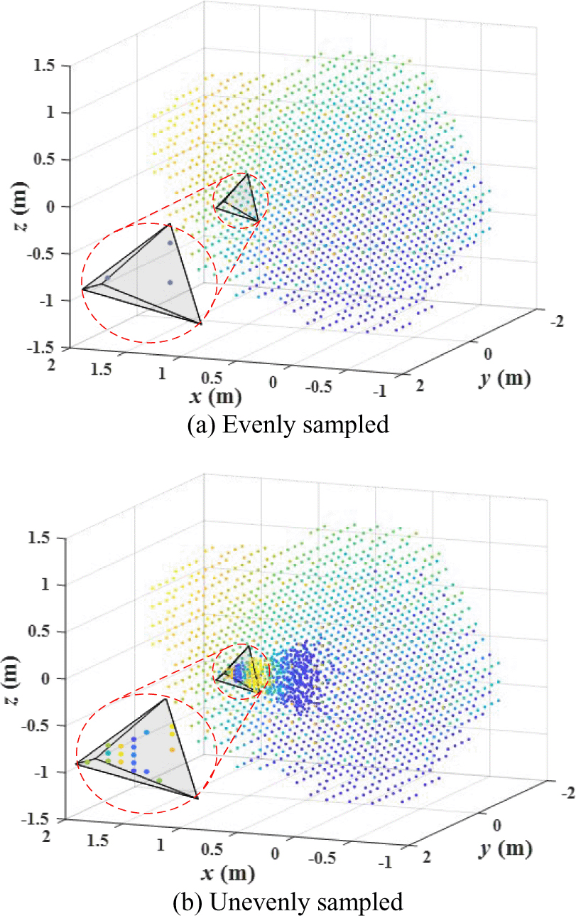
Figure 2: Diagram of the target’s dielectric constant data sampling.
Case 2: In some special application scenarios, the spatial distribution of the target’s dielectric constant may be given by a deterministic formula or a spatial spectrum function. The former case has been mentioned in [6] and will not be described in detail in this paper. Here, we propose a Monte Carlo method to access the dielectric constant spatial distribution by the spatial spectrum function. Monte Carlo method is a broad class of computational algorithms that rely on repeated random sampling to obtain numerical results [12]. It has been used to form complex terrain (such as rough sea surfaces [13] and mountainous regions [14]) and to modify phase factors [15, 16]. The atmosphere is a typical random medium, and its dielectric constant cannot be directly expressed by a deterministic formula related to spatial position. It can only be described with spectrum functions. Taking the atmosphere fluid as an example, the steps of using Monte Carlo method to obtain the dielectric constant spatial distribution are as follows:
Generate a 3-D Hermitian Gaussian random matrix .
Filter by the spatial spectrum of dielectric constant fluctuation , that is,
(1) The spatial spectrum of the atmospheric turbulence [8] is expressed as
(2) where is the position vector of a certain point in space, is the wave vector, and , l represents the size of turbulence, and are the outer scale and the inner scale of fluids, respectively, and is a constant.
Obtain the spatial distribution of the dielectric constant fluctuation by the inverse Fourier transform [12]. That is,
(3) Eventually, the dielectric constant spatial distribution of turbulence can be obtained by
(4) where is the average dielectric constant of the random media and is set to 1 for the turbulence case here. Combined with the given geometric profile, this kind of target can be reconstructed accurately.
B Modeling of the inhomogeneous dielectric target
Fine modeling is one of the key steps to explore the electromagnetic scattering characteristics of complex dielectric targets. Here, for the sake of fidelity, a large number of homogeneous tetrahedrons is used to reconstruct the inhomogeneous dielectric target rather than cubes used in [6]. Then, combined with the spatial distribution of dielectric constant, each tetrahedron is assigned an independent dielectric constant value. Specifically, four main steps are as follows:
Extract the vertex coordinates of each mesh element (tetrahedron) from the mesh file.
Sample dielectric constants in the target domain. As previously mentioned, the dielectric constant data can be obtained by a deterministic function related to the spatial position , the spatial spectrum function of random medium, or other simulation software.
Obtain the average dielectric constant of each tetrahedron. Let the four vertex coordinates of the ith tetrahedron be , , , and , respectively. Then, the tth sampling position in the ith tetrahedron must satisfy
(5) with
(6) (7) (8) Especially, if any other , then lies on the boundary (formed by the other three points other than ). Average the dielectric constant values of all sampling points in each tetrahedron, that is,
(9) where is the average dielectric constant of the tetrahedron, is the number of sampling points in the ith tetrahedron, and is the dielectric constant of the jth sampling point in the ith tetrahedron (including the sampling point on the surface).
Assign all average dielectric constant values to the corresponding tetrahedrons and then create a simulation model for electromagnetic scattering calculation.
C Electromagnetic scattering estimation
Here, the volume integral equation method of moments (VIE-MoM) is employed to simulate the scattering characteristics of inhomogeneous dielectric targets. According to the principle of volume equivalence, the scattered electric field can be written as [17]
| (10) |
where is the angular frequency, is the magnetic permittivity, is the wave number in free space, represents the equivalent volume current, represents the Green’s function, and
| (11) |
markedasmathboldr and represent position vectors of the observation point and the source point, respectively.
To solve (10), we adopt the Galerkin method with the SWG basis function
| (12) |
In eqn (12), is the area of common triangles, and and are volumes of tetrahedrons and , respectively. is the position vector of the free vertex pointing to the point inside tetrahedron , and is the position vector of the internal point pointing to the free vertex of tetrahedron . It should be noted that the half-SWG functions are also needed at the outer boundary. The geometry of the SWG function is shown in Figure 3. The details about the SWG functions are referred to [18].
Therefore, the corresponding impedance matrix equation can be built below
| (13) |
where is an impedance matrix with
| (14) |
where is the vector of unknowns, is the excitation vector with
| (15) |
In eqn (15), denotes the electric field of the incident wave. Eqn (13) is then solved by the generalized minimum residual method (GMRES) method [19].

Figure 3: The geometry of the SWG function.
D Software implementation and user guide
For the convenience of systematically analyzing the electromagnetic scattering characteristics of various inhomogeneous dielectric targets, we have developed a user-friendly software, which integrates the above-mentioned methods. To apply to most kinds of inhomogeneous dielectric targets, the dielectric constant information and geometric structure information of the target are grouped into a data input module of the software. The input module accepts the point cloud data file, deterministic formula, and spatial spectrum of the target’s dielectric constant and supports the geometric file in mainstream formats, such as.stp and .igs.
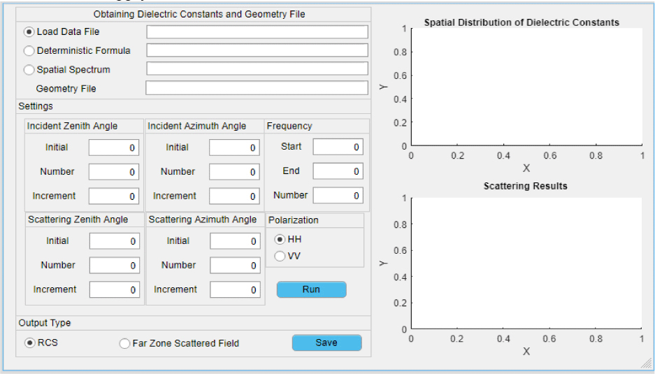
Figure 4: Designed software to model arbitrarily inhomogeneous dielectric targets.
In the settings of simulation frequency, incident angle, and scattering angle, we follow the setting habits of existing simulation software, including the initial value, terminal value, and number of samples. To link with different radar systems, two polarization modes, HH and VV, are given for users to choose. The software sets up two graph windows to visualize the spatial distribution of the target dielectric constant and the corresponding scattering results, as shown in the right part of Figure 4. At the same time, the software is equipped with a data output port, which is convenient for users to further analyze the scattering data. The interface for modeling the inhomogeneous dielectric targets is shown in Figure 4. The main operation procedures are as follows:
Select one of the following three methods to obtain the dielectric constant distribution in the target domain: loading the spatial point cloud data file of the target’s dielectric constant according to the entered data file path; entering the formula of the dielectric constant varying with position; entering the spatial spectrum function of the target’s dielectric constant. The corresponding geometry file is also required when adopting the latter twomethods.
Input simulation conditions, including incident zenith angle, incident azimuth angle, scattering zenith angle, scattering azimuth angle, polarization type, and frequency.
Press the “Run” button to start the electromagnetic scattering simulation for the target.
Press the “Save” button to save the scattering calculation results of the target.
Benefiting from the designed software, we have successfully carried out electromagnetic scattering simulations for various inhomogeneous dielectric targets, two of which are given in the next section.
III. SIMULATIONS WITH DESIGNED SOFTWARE
In this section, we first verify our algorithm by comparing the simulation results (given by the software) of an inhomogeneous sphere, of which the dielectric constant continuously varies with the spatial position, , with numerical solutions in [20]. Then, we apply our software to analyze electromagnetic scattering characteristics of a cloud-like inhomogeneous dielectric target, of which the dielectric constant is determined by a spatial spectrum function.
A Algorithm validation based on an inhomogeneous dielectric sphere
In this section, an inhomogeneous sphere is modeled by our software for verification. Specifically, the sphere is centered at with radius . The constitutive parameters are and . The reconstructed inhomogeneous sphere is shown in Figure 5. The magnitude of the far zone scattered field as a function of angle is calculated at using the proposed method in Section II.
The simulation results are compared with the numerical ones, as shown in Figure 6. The lines in Figure 6 are the results obtained by the proposed method, and the symbols indicate the results in [20]. It can be seen that they are in excellent agreement. This verifies the correctness of our algorithm (integrated into the designed software) in calculating the electromagnetic scattering from inhomogeneous targets and demonstrates that our method also has high solution accuracy same as [20].
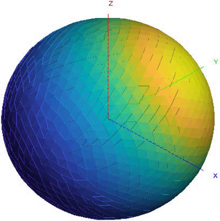
Figure 5: Reconstruction of the inhomogeneous sphere (, , and ) with our software.
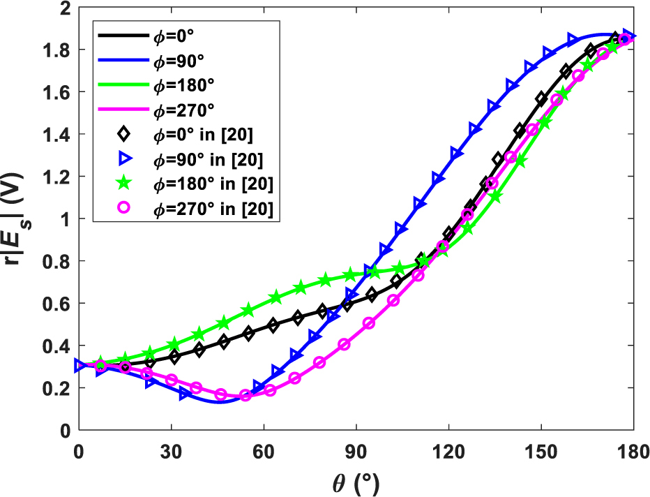
Figure 6: Magnitude of the far zone scattered field as a function of angle for the inhomogeneous sphere at .
B Electromagnetic scattering estimation of a cloud-like inhomogeneous target with the designed software
In practice, many objects have irregular structures, and the spatial distribution of dielectric constant usually cannot be expressed by a deterministic formula, such as the reservoir formation minerals, atmospheric turbulence, and so on. But many times, we can obtain their spatial spectrum functions of dielectric constants.
In this section, we introduce our software to solve this kind of random media and establish an inhomogeneous target with a cloud-like shape for instruction. The detailed modeling processes and scattering calculation of the cloud-like target based on our software (introduced in Section II) are as follows:
Get the geometry file information and input the spatial spectrum function. For the import of the geometry file, the supported file formats are “*.stp,” “*.igs,” etc. The geometry of the cloud-like inhomogeneous target is shown in Figure 7 (a). The maximum length of the media is 0.43 m in the -direction, 0.16 m in the -direction, and 0.22 m in the -direction. The spatial distribution of the dielectric constant is consistent with the atmosphere fluid, that is, (see Section II-A), and basic parameters of the fluid are shown in Table 1 . The outer scale is the geometry size of the target in x-, y-, and z-directions, and the inner scale of the fluid is set to 0.003 m. The constant and the average dielectric constant are set to and 1, respectively.
Table 1: Basic parameters of this kind of random media
L l L L L 0.43 m 0.16 m 0.22 m 0.003 m 10m 1 Generate the subdivision (tetrahedral elements) of the target according to the incident wave frequency . In this case, the incident wave frequency is set to 3 GHz; thus, 31,115 tetrahedral cells are obtained. The geometry after subdivision is shown in Figure 7 (b).
Determine the dielectric constant sampling points. According to the spatial spectrum function to obtain the dielectric constant spatial distribution of random media (see Section II-A), let ; then 357,911 sampling points are generated, as shown in Figure 7 (c). Notably, the more the sampling points, the more accurate it will be. The number of sampling points can be determined according to the specific application requirements.
Count the sampling points in each tetrahedral element according to eqn (5)–(8), calculate the average dielectric constant by (9), and assign the average dielectric constant to the corresponding tetrahedral element. The vertex coordinates and average dielectric constant of each tetrahedral element are shown in Table 2. The reconstruction of the cloud-like target is shown in Figure 7 (d).
Set simulation parameters. We set the start frequency to 300 MHz, the end frequency to 3 GHz, and the frequency increment to 37.5 MHz. The incident angle is set to (zenith angle) and (azimuth angle). The scattering angle is set to and (backscattered field). The detailed settings of the software in this case are shown in Figure 8.

Figure 7: Processes of reconstructing the inhomogeneous cloud-like target by our software.
Table 2: Vertex coordinates and average dielectric constant of each tetrahedral element
Tetra (m) (m) (m) (m) 1 (0.023,0.008,0.025) (0.036,0.013,0.025) (0.028,0.021,0.021) (0.023,0.009,0.015) 1.000200048 2 (0.023,0.008,0.025) (0.023,0.018,0.031) (0.028,0.021,0.021) (0.028,0.012,0.031) 1.000200255 3 (0.035,0.003,0.023) (0.036,0.013,0.025) (0.023,0.008,0.025) (0.023,0.009,0.015) 1.000199723 4 (0.062,0.014,
0.017)(0.059,0.004,
0.014)(0.060,0.016,
0.008)(0.052,0.007,
0.011)1.000199942 5 (0.062,0.014,
0.017)(0.052,0.007,
0.011)(0.052,0.020,
0.010)(0.051,0.016,
0.018)1.000199881 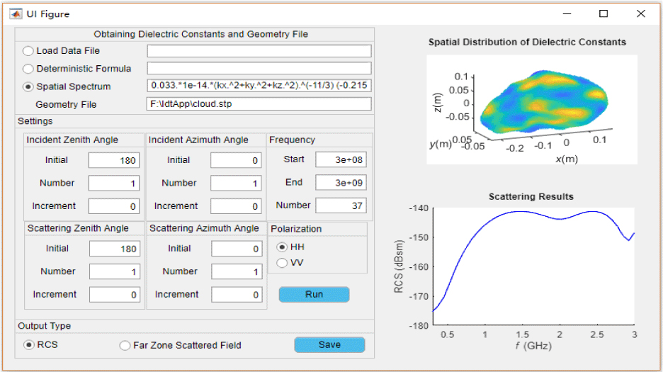
Figure 8: Detailed settings of the software for modeling the inhomogeneous cloud-like target.
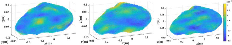
Figure 9: Three cases of the dielectric constant spatial fluctuation of the cloud-like target.
Run the software to call the MoM algorithm for the electromagnetic scattering calculation of the target and save the results for further analysis.
It should be noted that, for the sake of statistical significance, we randomly generate 30 samples. Figure 9 plots three samples of the spatial fluctuation of the cloud-like target’s dielectric constant.
Figure 10 plots the simulation results (monostatic RCS) of the cloud-like target at different incident frequencies (). The thin gray-blue lines are the results of several samples, and the thick blue line is the average value of the 30 samples.
The light blue area in Figure 10 denotes the 95% confidence interval (CI) of the cloud-like target’s RCS, which intuitively gives the amplitude range of echo signals from the target at each incident wave frequency.
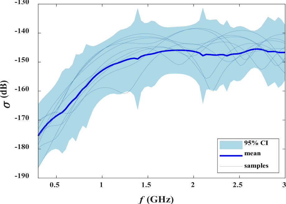
Figure 10: Monostatic RCS versus the incident wave frequency.
It should be emphasized that, from the thick blue line, we observe that as the frequency increases, RCS gradually increases and tends to be stable at about 1 GHz. According to the Bragg scattering conditions, the scattering is stronger when the effective scatterer size is half of the incident wavelength [21]. In this case, this means that the size of the cloud-like target should reach the decimeter level, which is indeed the case (see Table 1). This proves that our results are reasonable, that is, our software can be used for electromagnetic scattering simulation of random inhomogeneous dielectric targets. The turbulent scattering is also generally estimated by the empirical formula given in [8], which suggests that the scattering result of turbulence is proportional to the cubic root of electromagnetic frequency. However, this result does not strictly conform with Bragg’s law. Therefore, our method can be better used to analyze the spectral characteristics of turbulence than empirical formulas.
IV. CONCLUSION
A practical method to model the arbitrarily irregular-shaped and inhomogeneous dielectric targets is presented in this paper. The simulation example of an inhomogeneous sphere with a continuously varying dielectric constant fully verifies the correctness of our method, where the scattered far-field results obtained by the proposed method are consistent with numerical results. More importantly, a user-friendly software is developed based on our method and the designed software can be applied to calculate the electromagnetic scattering from complex, irregular, and random inhomogeneous targets. In this paper, a cloud-like target, of which the dielectric constant distribution is obtained by Monte Carlo simulation with the spatial spectrum of atmospheric turbulence dielectric constant fluctuation, is taken as an example, and the results are in accordance with the Bragg’s law. This fully verifies the wide applicability of the designed software.
Added up, our software can not only be applied to modeling the inhomogeneous target with a deterministic dielectric constant function and a regular shape but also the complex target with a spatial spectrum function and an irregular shape. It provides a convenient way to solve the electromagnetic scattering simulation problems of complex inhomogeneous targets in engineering applications.
ACKNOWLEDGMENT
This work was supported by the National Natural Science Foundation of China under Grant 61771375 and Grant 92052106.
REFERENCES
[1] G. Zhang, Wave Scattering by a Single Particle from: Weather Radar Polarimetry, CRC Press, London, 2016.
[2] C. Li, X. Chen, and X. Liu, “Cognitive tropospheric scatter communication,” IEEE Trans. Vehicul. Technol., vol. 67, no. 2, pp. 1482-1491, Feb. 2018.
[3] R. Grant, The Radar Game: Understanding Stealth and Aircraft Survivability, Mitchell Institute Press, Mitchell, 2010.
[4] K. Shariff and A. Wray, “Analysis of the radar reflectivity of aircraft vortex wakes,” J. Fluid Mech., vol. 463, pp. 121-161, Jan. 2002.
[5] X. Wang, J. Li, L. Qu, C. Pang, and F. Niu, “Temporal evolution of the RCS of aircraft wake vortices,” Aerosp. Sci. Technol., vol. 24, no. 2, pp. 204-208, Feb. 2013.
[6] A. Farahbakhsh, D. Zarifi, and A. Abdolali., “Using MATLAB to model inhomogeneous media in commercial computational electromagnetics software,” Applied Computational Electromagnetics Society (ACES) Journal, vol. 30, no. 9, pp. 1003-1007, Sep. 2015.
[7] P. Zhang, B. Du, and T. Dai, Radar Meteorology, Meteorology Press, Beijing, 2000.
[8] I. V. Tatarski, Wave Propagation in a Turbulent Medium, Courier Dover Publications, USA, 2016.
[9] F. T. Ulaby and U. Ravaioli, Fundamentals of Applied Electromagnetics, Prentice-Hall, USA, 2015.
[10] N. P. Weatherill and O. Hassan, “Efficient three-dimensional Delaunay triangulation with automatic point creation and imposed boundary constraints,” Int. J. Numer. Meth. Eng., vol. 37, no. 12, pp. 2005-2039, 1994.
[11] N. M. Noor, M. M. Al Bakri Abdullah, A. S. Yahaya, and N. A. Ramli, “Comparison of linear interpolation method and mean method to replace the missing values in environmental data set,” Mater. Sci. Forum, vol. 803, pp. 278-281, 2014.
[12] V. M. Jansoone, “Dielectric properties of a model fluid with the Monte Carlo method,” Chem. Phys., vol. 3, pp. 78-86, 1974.
[13] X. Meng, L. Guo, S. Chai, and Y. Jiao, “The investigation of backscattering characteristics of 3-D local sea surface with time-varying overturning wave crest,” Applied Computational Electromagnetics Society (ACES) Journal, vol. 33, no. 6, pp. 675-682, 2021.
[14] C. Miesch, X. Briottet, Y. Kerr, and F. Cabot, “Monte Carlo approach for solving the radiative transfer equation over mountainous and heterogeneous areas,” Appl. Optics, vol. 38, no. 36, pp. 7419-7430, 1999.
[15] M. Man, Z. Lei, Y. Xie, B. Chen, and Q. Wang, “Monte Carlo simulation of the echo signals from low-flying targets for airborne radar,” Int. J. Antenn. Propag., vol. 2014, Nov. 2014.
[16] T. Kamalakis, T. Sphicopoulos, S. S. Muhammad, and E. Leitgeb, “Estimation of the power scintillation probability density function in free-space optical links by use of multicanonical Monte Carlo sampling,” Opt. Lett., vol. 31, no. 21, pp. 3077-3079, 2006.
[17] W. C. Gibson, The Method of Moments in Electromagnetics, CRC Press, New York, 2015.
[18] D. H. Schaubert, D. R. Wilton, and A. W. Glisson, “A tetrahedral modeling method for electromagnetic scattering arbitrarily shaped inhomogeneous dielectric bodies,” IEEE T. Antenn. Propag., vol. 32, no. 1, pp. 77-85, 1984.
[19] J. Drkoov, A. Greenbaum, M. Rozloník, and Z. Strako, “Numerical stability of GMRES,” BIT., vol. 35, no. 3, pp. 309-330, 1995.
[20] E. Khodapanah, “Calculation of electromagnetic scattering from an inhomogeneous sphere,” IEEE T. Antenn. Propag., vol. 67, no. 3, pp. 1771-1778, 2019.
[21] A. S. Gurvich and A. I. Kon. “The backscattering from anisotropic turbulent irregularities,” J. Electromagnet Wave, vol. 6, no. 6, pp. 107-118, Mar. 2015.
BIOGRAPHIES

Muyu Hou received the B.S. degree in applied physics from Xi’an Shiyou University, Xi’an, China, in 2015. She is currently working toward the Ph.D. degree in radio physics with Xidian University, Xi’an, China. Her current research interests include tropospheric scatter propagation and tropospheric artificial metamorphosis.

Shuhong Gong was born in Shanxi, China, in 1978. He received the B.S. degree in physics education from Shanxi Normal University, Xi’an, China, in 2001, and the M.S. and Ph.D. degrees in radio physics from Xidian University, Xi’an, China, respectively, in 2004 and 2008.
He is currently a Professor with Xidian University. His research work has been focused on novel antenna design, radio wave propagation, and their applications.

Yanchun Zuo received the B.E. degree from Xinyang Normal University, Xinyang, China, in 2013 and the M.E. degree from Xidian University, Xi’an, China, in 2014. He is currently working toward the D.E. degree in electromagnetic field and microwave technology. His main research interests include electromagnetic scattering modeling and scattering measurements.

Yu Liu received the B.S. degree in applied physics from the Xi’an University of Posts & Telecommunications, Xi’an, China, in 2016. He is currently working toward the Ph.D. degree in radio physics with Xidian University, Xi’an, China, under the guidance of Prof. S. Gong. His current research interests include underwater wireless communication and mechanical antenna.
ACES JOURNAL, Vol. 37, No. 5, 526–534.
doi: 10.13052/2022.ACES.J.370502
© 2021 River Publishers