Triple Bands UWB Antenna with Minimum Printed Area for Power Harvesting Applications
Nourhan D. Sehsah, Tamer G. Abouelnaga, and Hamdi A. Elmikati
1Microstrip Circuits Department
Electronics Research Institute, Cairo 4473221, Egypt
tamer@eri.sci.eg
2Higher Institute of Engineering and Technology, Kafr Elsheikh, Egypt
nourdiab1010@gmail.com
3Faculty of Electronic Engineering, Mansoura University, Mansoura 35516, Egypt
h.elmikati@gmail.com
Submitted On: February 26, 2022; Accepted On: June 29, 2022
Abstract
In this paper, a triple-band ultra-wideband UWB eight elements monopole antenna array is proposed. This antenna array is designed with the minimum printed area and is prepared for wireless local area network (WLANs) power harvesting applications. It covers the bands of 2.4 GHz and 5 GHz, which makes it suitable for Wi-Fi frequencies to harvest their power. The eight-element antenna array dimensions are 28.5 cm by 15 cm. These dimensions are chosen for the mini-solar cell integration process. Low-cost FR4 material is used as a substrate. The proposed antenna’s measured reflection coefficient is compared with its simulated counterpart and is founded in good harmony.
Index Terms: Antenna, monopole, power harvesting, WLAN.
I. INTRODUCTION
In previous research, several antennas are proposed for energy harvesting applications. Wi-Fi technology is commonly used in homes, offices, cafes, etc. 2.4 GHz and 5 GHz are used by the Wi-Fi networks. Upper and lower WLAN frequency bands are extended to (5.725 - 5.825) GHz and (5.15 - 5.35) GHz, respectively [1]. Radio-frequency RF energy can be harvested by A novel broadband CPW-fed fractal [2] and promoted to harvest energy at WiMAX, LTE 2600, Wi-Fi 2.4 GHz, WLAN, ISM, and 5G frequency bands [3, 4], a dual-band rectifier with broad-band 14 quasi-Yagi antenna that used in same application of harvesting has printed area of 9814 mm2 [5]. In [6] the antenna was increased Front to a Back (F/B) ratio with a printed area of 2471.38 mm, but the DSRMA [7]with a printed area of 4775 mm, and in [8] is 1476 mm. The radiation patterns of omnidirectional antennas have a good performance when three pairs of dipole radiators are located back-to-back [9], also preferable to harvesting RF energy from ambient sources efficiently [10]. Decent RF-to-DC conversion efficiency was achieved between 40%–60% at 0 dBm by a double-sided Printed monopole antenna that has a printed area of 9053 mm [11]. The energy harvester’s main elements are the rectifier array and antenna array. The first was responsible for converting the RF energy to DC and the last was for capturing the RF waves. The energy harvester can be combined with a dual-band microstrip patch antenna and DC voltage measured at the output [12].
Table 1: Previous power harvesting antennas structures and parameters
| Ref. [5] | ||
|---|---|---|
| Printed area (mm) | 9814 | |
| Frequency bands (GHz) | 1.8–2.2 GHz | |
| Gain (dBi) | 10.9 dB at 1.85 GHz and 13.3 dB at 2.15 GHz | |
| Directivity (dBi) | Unspecified | |
| 3 dB BW | E-plane | 30.0 deg at 1.85 GHz and 20.0 deg at 2.15 GHz |
| H-plane | 100.0 deg at 1.85 GHz and 82.0 deg at 2.15 GHz | |
| Ref. [6] | ||
| Printed area (mm) | 2471.38 | |
| Frequency bands (GHz) | 1.95–2.45 GHz | |
| Gain (dBi) | 8.3 dB at 1.95 GHz and 7.8 dB at 2.45 GHz | |
| Directivity (dBi) | Unspecified | |
| 3 dB BW | E-plane | 65.9 deg at 1.95 GHz and 83.9 deg at 2.45 GHz . |
| H-plane | 81.5 deg at 1.95 GHz and 75.1 deg at 2.45 GHz. | |
| Ref. [7] | ||
| Printed area (mm) | 4775 | |
| Frequency bands (GHz) | (0.8–1.05) GHz, (1.6–2.2) GHz, and (2.4–3) GHz | |
| Gain (dBi) | 15.8 dB at 1.6 GHz | |
| Directivity (dBi) | Unspecified | |
| 3 dB BW | E-plane | 110 deg |
| H-plane | Unspecified | |
| Ref. [8] | ||
| Printed area (mm) | 1476 | |
| Frequency bands (GHz) | 2.4–2.5 GHz | |
| Gain (dBi) | Unspecified | |
| Directivity (dBi) | Unspecified | |
| 3 dB BW | E-plane | 89.0 deg |
| H-plane | 98.0 deg | |
| Ref. [11] | ||
| Printed area (mm) | 9053 | |
| Frequency bands (GHz) | 0.85–5.5 GHz | |
| Gain (dB) | 5.3 dBi | |
| Directivity (dBi) | Unspecified | |
| 3 dB BW | E-plane | 39.0 deg |
| H-plane | Omni direction |
The main challenge is to obtain a high-efficiency and miniature-zed antenna array [13]. Table 1 shows a comparison among different proposed antenna structures that were used in RF energy harvesting. According to the equation of Friis transmission, the harvested power can be estimated by [14–16] as
| (1) |
where is the gain of the receiver antenna, is the gain of the transmitter antenna, is the transmitted power, is the received Power, is the wavelength of the electromagnetic signal, and D is the distance between the transmitter and receiver antennas. This paper aims to introduce a UWB antenna with a minimum printed area for power harvesting applications without losing the omnidirectional radiation properties. Three designs are introduced and compared with each other. These designs are circular patch monopole antenna, triple UWBs monopole antenna, and triple UWBs monopole antenna with the minimum printed area. Minimum printed area of 1624.56 is obtained based on the current distribution investigation. The proposed antennas are compared with each other for their suitability for power harvesting operation and visibility to be integrated with a solar cell unit. The candidate antenna structure is used to develop an eight elements antenna array. The array dimensions are designed to be integrated with a solar cell unit to improve its efficiency and to maintain its transparency as much as possible. Our goal is to harvest the greatest power from the Wi-Fi bands (2.4 to 2.5) GHz and (5.1 to 5.8) GHz [17]. The antenna reflection coefficient is measured and compared with its simulated counterpart. Also, the radiation properties of the proposed antenna array are investigated for their power harvesting application suitability.
Table 1 shows the difficulty to cover the Wi-Fi bands with the minimum printed area and omnidirectional characteristics.
II. MONOPOLE ANTENNA DIFFERENT STRUCTURES, DESIGN, AND SIMULATION
For Wi-Fi RF power harvesting purposes, a three different antenna structures are designed and investigated. The same FR4 substrate with a dielectric constant of 4.4, loss tangent of 0.02, and thickness of 1.6 mm at a frequency of 1 GHz is used for all antennas. The proposed three structures are compared to each other and the most candidate one is used to be integrated with a solar cell unit.
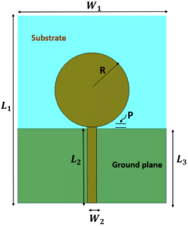
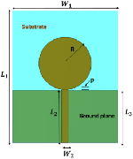
Figure 1: Circular monopole antenna.
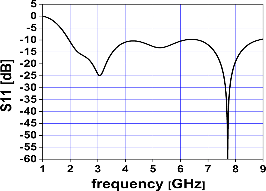
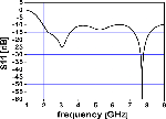
Figure 2. (a): Circular patch monopole antenna reflection coefficient versus frequency.
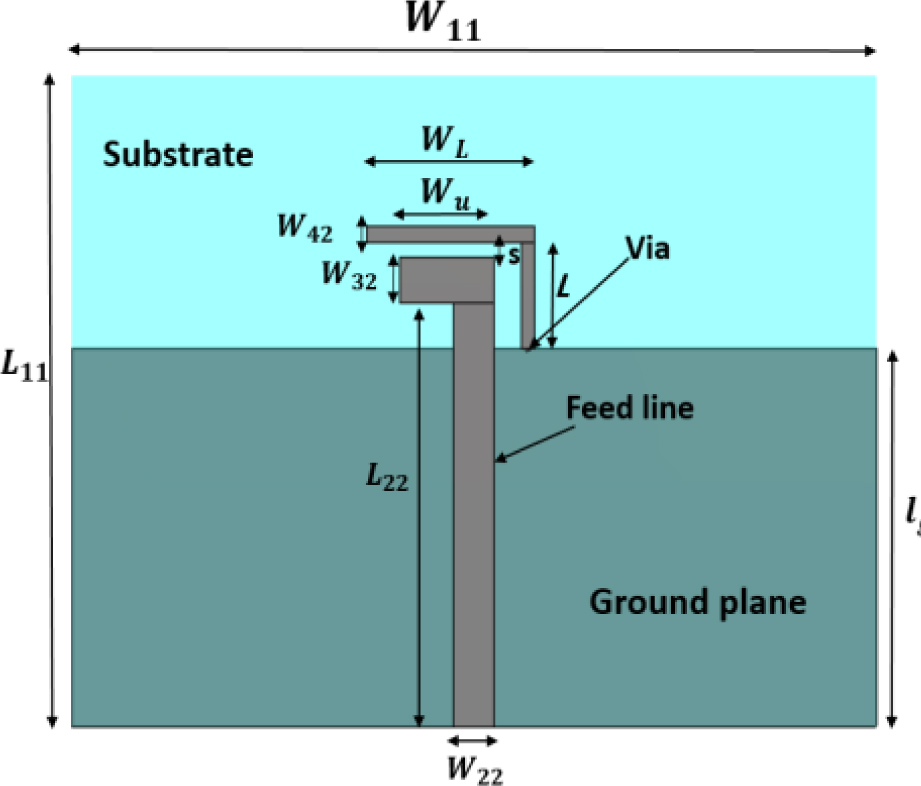
Figure 2. (b): Circular patch monopole antenna current distribution at 3.1 and 7.7 GHz.
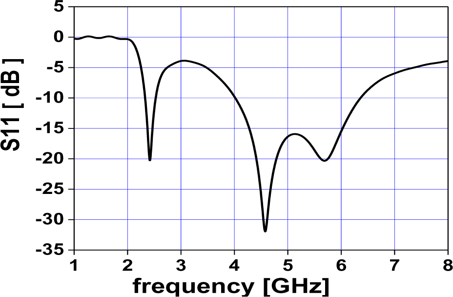
Figure 2. (c): Circular patch monopole antenna radiation pattern at 3.1 and 7.7 GHz.
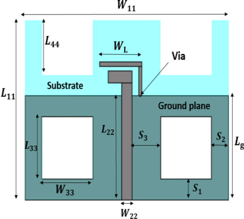
Figure 3: Triple bands monopole antenna.
A Circular disk monopole antenna
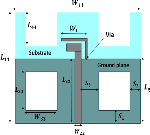
Figure 1 shows the printed monopole antenna that is proposed to collect Wi-Fi RF power, efficiently. The radius of radiating patch can be calculated by [18] as
| (2) |
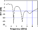
where P is the gap between the feedline length and ground plane length, K =1.15 constant, and is lower cut-off frequency. Considering of 2 GHz, the patch radius is found to be 11.8 mm. The feed line width is calculated using [19] and found to be 3 mm. Other dimensions are optimized using the CST simulator and are found to be = 60.4 mm (substrate length), = 48 mm (Substrate width), = 24 mm (ground plane length), = 24.5 mm (feed line length), = 3 mm (feed line width), and R = 12 mm (circular patch radius). This type of monopole antenna suffers from a large occupation area which reaches 525.89 mm at the top and 1152 mm at the bottom. Figure 2 (a) shows the simulated return loss () and it is observed that the bandwidth is extended from 2 GHz to 9 GHz, also current distribution and radiation pattern appear in Figures 2 (b) and (c) at frequencies 3.1 GHz and 7.7 GHz
Table 2: Proposed triple-band antenna geometry
| L | s | |||||||||
| 60 | 43 | 3 | 28 | 12.5 | 7 | 25 | 7 | 3 | 1 | 1 |
Table 3: Different dimensions for and B.W at each dimension = 12.5 mm and = 7 mm
| B.W | |
|---|---|
| 27 mm | (2.52–2.62) GHz |
| 26 mm | (2.48–2.59) and (4.73–6.64) GHz |
| 25 mm | (2.41–2.55) and (3.84–6.55) GHz |
B Triple bands planar monopole antennas
Based on [20], a triple-band monopole antenna with a shorted parasitic inverted -L wire is designed to cover RF frequency bands at 2.4 GHz, 5.2 GHz, and 5.8 GHz, Figure 3. The reflection coefficient is shown in Figure 4 (a), while the current distribution and radiation pattern at resonant frequencies of 2.43 GHz, 4.6 GHz, and 5.7 GHz are shown in Figures 4 (b) and (c). Table 2 shows the dimensions of the proposed antenna in mm, and a radius equal to 0.2 mm.
Table 3 shows the effect of varying the length of the ground plane on the lower (2.4 - 2.5) GHz and the higher (5.1-5.8) GHz frequency bands. Tables 4 and 5 show the effect of varying and on the lower and higher frequency bands. Bandwidth of 127 MHz (2.418-2.545) GHz and 2.702 GHz are obtained when , , and are chosen to be 25 mm, 12.5 mm, and 7 mm respectively
Table 4: Different dimensions for and B.W at each dimension = 25 mm and = 7 mm
| B.W | |
|---|---|
| 12.3 mm | (2.45–2.57) and (3.86–6.56) GHz |
| 12.5 mm | (2.42–2.55) and (3.84–6.55) GHz |
| 13 mm | (2.35–2.48) and (3.83–6.53) GHz |
Table 5: Different dimensions for and B.W at each dimension = 12.5 mm and = 25 mm
| B.W | |
|---|---|
| 6.7 mm | (2.41–2.54) and (3.87–6.66) GHz |
| 7 mm | (2.41–2.55) and (3.84–6.56) GHz |
| 7.5 mm | (2.43–2.56) and (3.82–6.39) GHz |
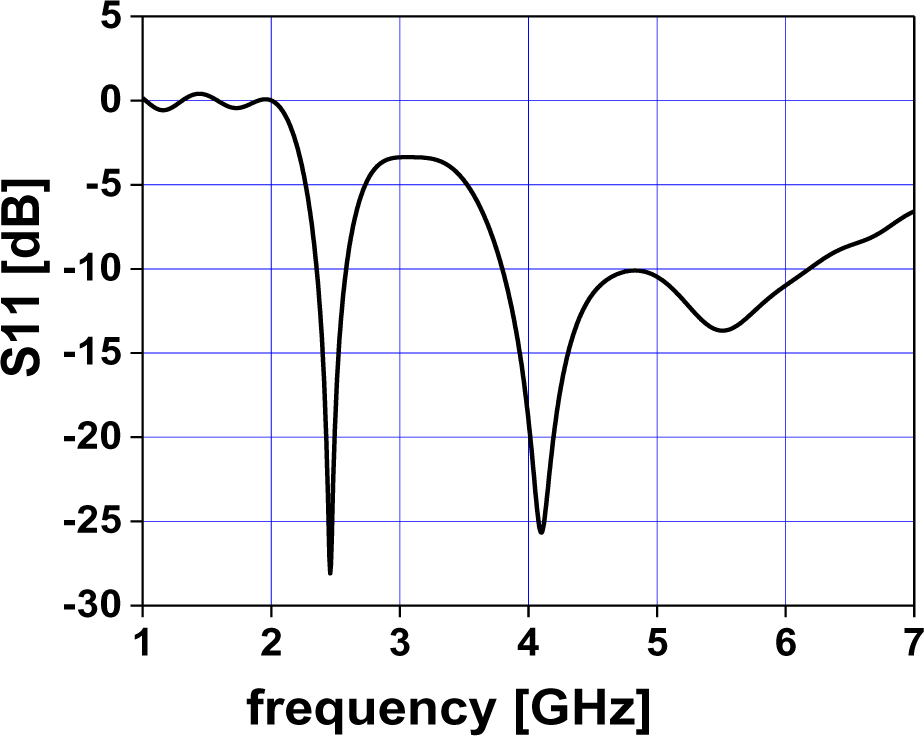
Figure 4. (a): Triple bands monopole antenna reflection coefficient versus frequency.
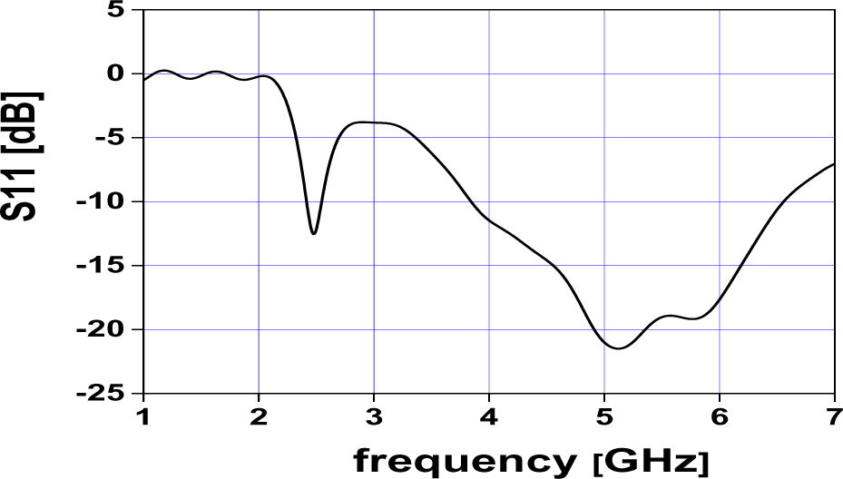
Figure 4. (b): Triple bands monopole antenna current distribution at (1) 2.43, (2) 4.6, and (3) 5.7 GHz.

Figure 4. (c): Triple bands monopole antenna radiation pattern at 2.43, 4.6, and 5.7 GHz, respectively.
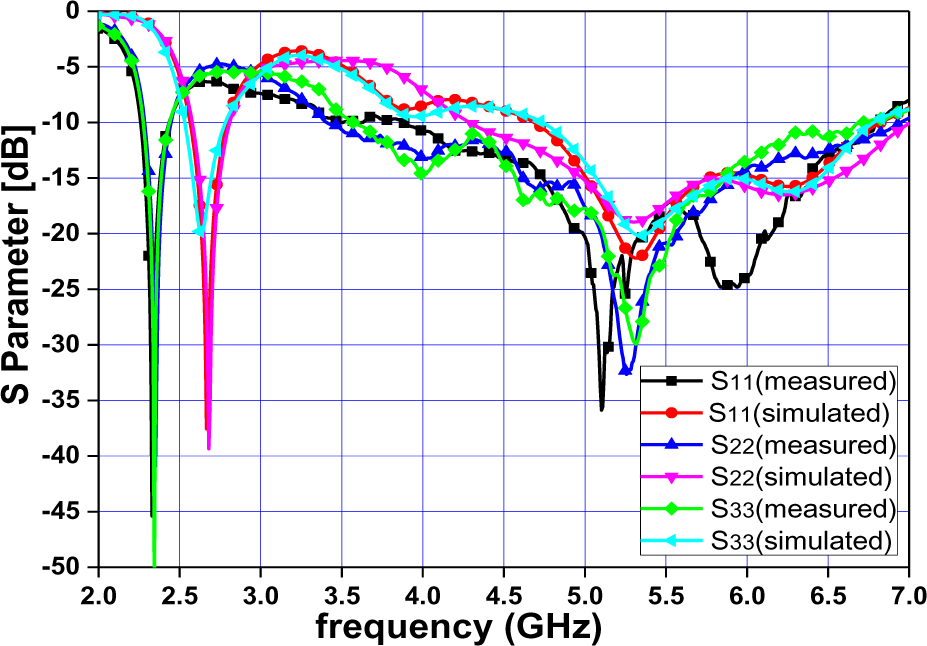
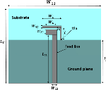
Figure 5: Triple bands planar monopole antennas with rectangular slots.
C Triple bands planar monopole antennas rectangular slots
Based on Section II-B, the above elements with =12.5 mm is the main radiator that contributor to the frequency 2.43 GHz and 4.6 GHz and there is a strong current at the via, but at 5.7 GHz the main radiator is the bottom element with =7mm, after that we removed the emptied places from the ground plane where there are no currents as shown in (Figure 5).
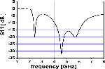
The resonant frequencies were shifted from (2.43 to 4.1) GHz, (4.6 to 4.1) GHz, and (5.7 to 5.5) GHz. The dimensions of the rectangular slots are =15 mm and = 15 mm, =13 mm and spaced by = 10 mm from the center of the feed line. The rectangular slot is also Separated by = 5 mm and = 5 mm from the substrate edges. Figure 6 shows the reflection coefficient, current distribution, and radiation pattern at 2.46, 4.1, and 5.5 GHz.
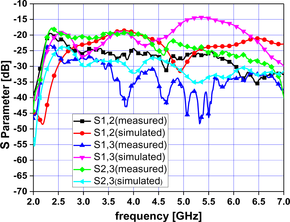
Figure 6. (a): Triple bands monopole antenna with rectangular slots reflection coefficient versus frequency.
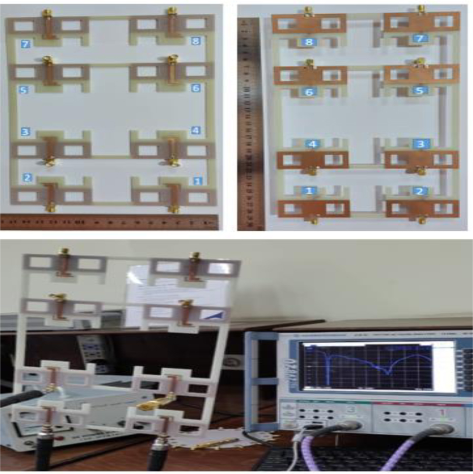
Figure 6. (b): Triple bands monopole antenna with rectangular slots current distribution at (1) 2.46, (2) 4.1, and (3) 5.5 GHz.
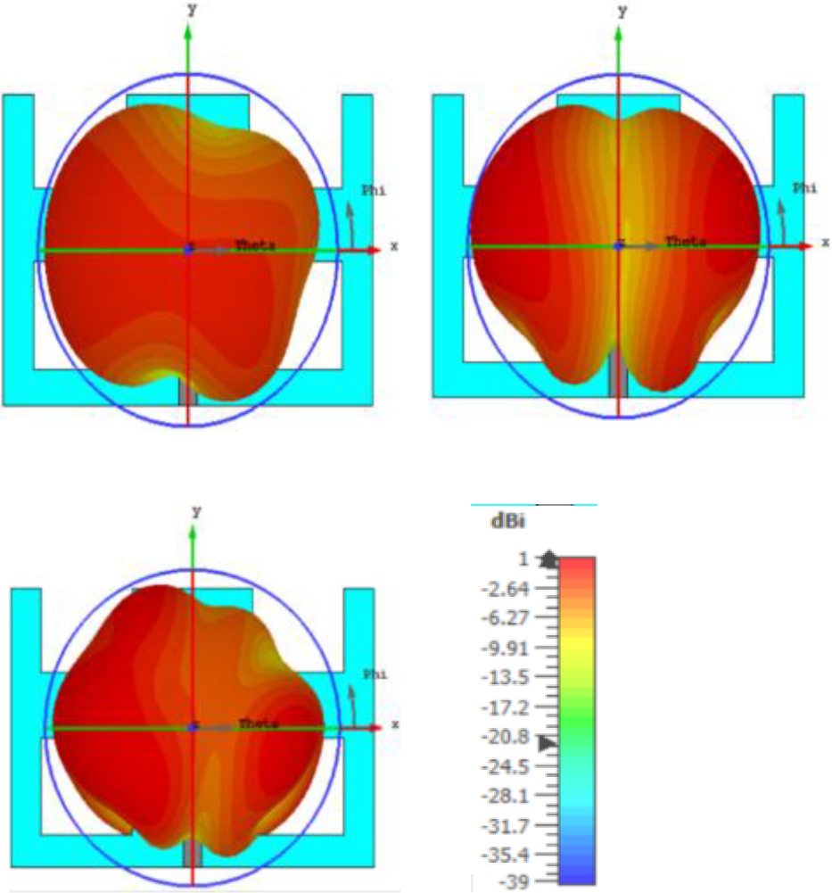
Figure 6. (c): Triple bands monopole with rectangular slots radiation pattern at 2.46, 4.1, and 5.5 GHz, respectively.
D Comparison among the proposed structures

Figure 7: Triple bands monopole antenna with rectangular slots integrated with the aforementioned mini-solar cell reflection coefficient.
It’s observed that the printed area of the triple bands’ monopole antenna is less than that of the circular monopole by 3.2% as compared to 30% for the proposed triple bands with rectangular slots. Thus, the antenna turned to mini-transparent and overcome its main problem which is represented in a large area, Table 6.

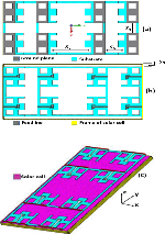
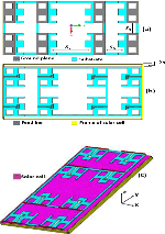
Figure 8: Structure of proposed antennas: (a) bottom view; (b) top view; (c) antennas with eight-element.
Referring to Tables 1 and 6, it is observed the proposed triple bands with two slots monopole antenna present the minimum printed area with an almost omnidirectional radiation H-plane pattern.

Figure 9: Simulated and measured reflection coefficient of the proposed array.
Table 6: Comparison among proposed structure
| Circular monopole antenna | ||
|---|---|---|
| Printed area (mm) | 1677.89 | |
| Frequency bands (GHz) | From 1.96 to 6.15 GHz and 6.64 to 8.83 GHz | |
| Gain (dB) | 2.86 dB at 3.1 GHz and 6.218 dB at 7.7 GHz | |
| Directivity (dB) | 3.4 dB at 3.1 GHz and 6.44 dB at 7.7 GHz | |
| 3 dB BW | E-plane | 98.4 deg at 3.1 GHz and 34.9 deg at 7.7 GHz |
| H-plane | 216.9 deg at 3.1 GHz and 71.9 deg at 7.7 GHz | |
| Triple bands monopole antenna | ||
| Printed area (mm) | 1624.56 | |
| Frequency bands (GHz) | From 2.33 to 2.53 and 4.02 to 6.36 | |
| Gain (dB) | 2.32 dB at 2.43 GHz, 3.86 dB at 4.6 GHz, and 3.83 dB at 5.7 GHz | |
| Directivity (dB) | 2.9 dB at 2.43 GHz, 4.05 dB at 4.6 GHz, and 4.156 dB at 5.7 GHz | |
| 3 dB BW | E-plane | 95.1 deg at 2.43 GHz, 125.6 deg at 4.6 GHz, and 146.0 deg at 5.7 GHz |
| H-plane | 285.8 deg at 2.43 GHz, 56.9 deg at 4.6 GHz, and 47.0 deg at 5.7 GHz | |
| Triple bands monopole antenna with rectangular slots | ||
| Printed area (mm) | 1174.56 | |
| Frequency bands (GHz) | From 2.35 to 2.58 GHz and 3.79 to 6.14 GHz | |
| Gain (dB) | 0.5 dB at 2.46 GHz, 2.467 dB at 4.1 GHz, and 2.915 dB at 5.5 GHz. | |
| Directivity (dB) | 2.94 dB at 2.46 GHz, 3.9 dB at 4.1 GHz, and 4.167 dB at 5.5 GHz | |
| 3 dB BW | E-plane | 257.3 deg at 2.46 GHz, 124.0 deg at 4.1 GHz, and 50.5 deg at 5.5 GHz |
| H-plane | 95.2 deg at 2.46 GHz, 80.4 deg at 4.1 GHz, and 56.3 deg at 5.5 GHz |
III. PROPOSED EIGHT-ELEMENT ANTENNA
Table 7: Gain, directivity, and efficiency at 2.44 GHz
| At 2.44 GHz | |||
|---|---|---|---|
| Ant. No. |
G (dBi) | D (dBi) | Efficiency % |
| 1 | 4.660 | 5.316 | 85.99 |
| 2 | 5.569 | 6.285 | 84.79 |
| 3 | 5.052 | 5.629 | 87.55 |
| 4 | 4.702 | 5.336 | 86.42 |
| 5 | 4.659 | 5.317 | 85.95 |
| 6 | 5.569 | 6.286 | 84.79 |
| 7 | 5.053 | 5.632 | 87.52 |
| 8 | 4.702 | 5.336 | 86.42 |
Table 8: Gain, directivity, and efficiency at 5.44 GHz
| At 5.44 GHz | |||
|---|---|---|---|
| Ant. No. |
G (dBi) | D (dBi) | Efficiency % |
| 1 | 5.719 | 6.334 | 86.80 |
| 2 | 7.047 | 7.737 | 85.30 |
| 3 | 6.388 | 7.054 | 85.80 |
| 4 | 6.353 | 7.093 | 84.34 |
| 5 | 5.727 | 6.342 | 86.80 |
| 6 | 7.045 | 7.736 | 85.30 |
| 7 | 6.379 | 7.045 | 85.79 |
| 8 | 6.354 | 7.093 | 84.34 |

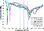
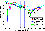
Figure 10: Simulated and measured coupling of proposed antenna array.

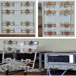
Figure 11: Fabricated antenna array elements with VNA.
The developed antenna (Section II-C) is used as an element of the 8-element antenna array. The dimensions of the array are set to be (165 285) mm which is the same as the mini-solar cell unit which will be used to test the presence of the mini-solar cell material on antenna performance. The antenna array element is separated by the horizontal distance =30 mm and vertical distance =27 mm. Each four elements group is separated by a vertical distance =59 mm, and =7.5 mm, Figure 8. The solar cell material is considered to be glass with =3.9 and = 0.0054. An aluminum metal frame is also considered.
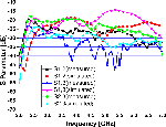
Figure 7 shows a bandwidth that extends from 2.35 GHz to 2.58 GHz and from 3.79 GHz to 6.14 GHz is achieved when the antenna is integrated with the aforementioned mini-solar cell. The simulated and measured reflection and coupling coefficients are shown in Figures 9 and 10, respectively.

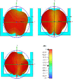
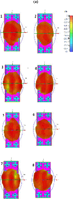
Figure 12. (a): Radiation pattern at 2.44 GHz.
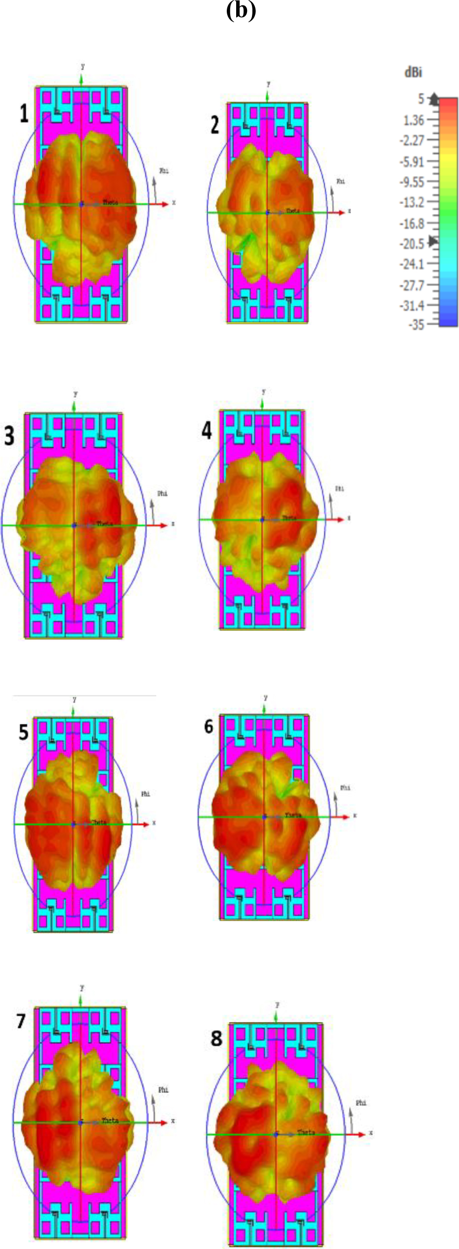
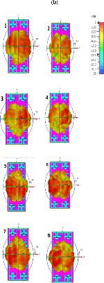
Figure 12. (b): Radiation pattern at 5.44 GHz.
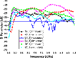
The simulated bandwidth extends from 2.35 GHz to 2.58 GHz and 3.79 GHz to 6.14 GHz as compared with the measured counterpart which extends from 2.26 GHz to 2.42 GHz. and from .4.18 GHz to 6.8GHz. A minimum isolation of 20 dB is obtained over the operating frequency lower and higher bands.
R&S ZVB 20 Vector Network Analyzer is used to measure the reflection coefficient of the proposed antenna array elements, Figure 11. The radiation pattern of the proposed antenna array when integrated with the solar cell unit is investigated shown in Figure 12 at resonance frequencies of 2.44 GHz and 5.44 GHz. Tables 7 and 8 show the gain, directivity, and efficiency of each antenna element at 2.44 GHz and 5.44 GH, respectively.
IV. CONCLUSION
This paper presented a transparent 8-elements antenna array that is ready to be merged with solar cell units. It is designed to be operated at the Wi fi bands of 2.4 GHz and5 GHz. Two frequency bands of 2.4 GHz to 2.5 GHz and 5.1 GHz to 5.8 GHz with acceptable reflection coefficients below 10 dB are obtained. Good agreement between experimental and simulated results is obtained. This antenna array is intended for collecting the largest amount of power from several wireless communication bands by using eight antenna elements with suitable parameters in terms of Gain and radiation pattern.
REFERENCES
[1] K. S. Ryu and A. A. Kishk, “UWB antenna with single or dual band notches for lower WLAN,” Antennas Propagat, vol. 57, no. 12, pp. 3942-3950, Dec. 2009.
[2] X. Bai, J.-W. Zhang, L.-J. Xu, and B.-H. Zhao, “A broadband CPW fractal antenna for RF energy harvesting,” Applied Computational Electromagnetic Society (ACES) Journal, vol. 33, no. 5, pp. 482-487, May 2018.
[3] T. Hamza, B. Adel, and B. M Reda, “A low-cost elliptical triple-band antenna for RF energy harvesting applications,” in Proc. Int. Conf. Renewable Energies Developing Countries, Marrakech, Morocco, pp. 29-30, Jun. 2020.
[4] N. A. Eltresy, A. M. Abd Elhamid, D. M. Elsheakh, H. M. Elshennawy, and E. A. Abdallah, “Silver sandwiched ITO based transparent antenna array for RF energy harvesting in 5G mid-range of frequencies,” IEEE Access, vol. 9, pp. 49476-49486, Mar. 2021.
[5] H. Sun, Y. X. Guo, M. He, and Z. Zhong, “A dual-band rectenna using broad-band yagi antenna array for ambient RF power harvesting,” IEEE, vol. 12, pp. 918-921, Jul. 2013.
[6] M. Aboualalaa, A. B. Abdel-Rahman, A. Allam, and H. Elsadek, “Design of dual band microstrip antenna with enhanced gain for energy harvesting applications,” IEEE, Antennas Wirel. Propag. Lett., vol. 16, pp. 1622-1626, Jan. 2017.
[7] M. Kurvey and A. Kunte, “Design and optimization of stepped rectangular antenna for RF energy harvesting,” in Proc. IEEE Int. Conf. Commun. Inform. Comput. Technol., Mumbai, India, pp. 2-3,Feb. 2018.
[8] E. L. Chuma, L. T. Rodriguez, Y. Lano, L. L. B. Roger, and M. A. S. Soriano, “Compact rectenna based on a fractalgeometry with a high conversion energy efficiency per area,”IEEE, IET Microwaves, Antennas Propag., vol. 12, pp. 173-178, 2018.
[9] Y. J. Wu, B. H. Sun, J. F. Li, and Q. Z. Liu, “Triple-band omni-directional antenna for WLAN application,” Progress Electromagn. Res. PIER, vol. 76, pp. 477-484, Aug. 2007.
[10] N. Mao, D. Yang, and Y. Tang, “A dual circularly polarized rectenna with wide-beam,” in Proc. IEEE, Int. Symp. Antennas Propag. (ISAPE), Hangzhou, China, pp. 3-6, Dec. 2018.
[11] S. Agrawal, M. S. Parihar, and P. N. Kondekar, “Broadband rectenna for radio frequency energy harvesting application,” IETE J. Res., vol. 64, pp. 347-353, Aug. 2017.
[12] O. Amjad, S. W. Munir, S. T. Imeci, and A. Ö. Ercan, “Design and implementation of dual band microstrip patch antenna for WLAN energy harvesting system,” Applied Computational Electromagnetic Society (ACES) Journal, vol. 33, no. 7, pp. 746-751, Jul. 2018.
[13] U. Olgun, C. C. Chen, and J. L. Volakis, “Design an efficient ambient Wi-Fi energy harvesting system,” IET Microwaves, Antennas Propag., vol. 6, pp. 1200-1206, Mar. 2012.
[14] S. Manavalan and P. Anumuthu, “Design of tri-band microstrip patch rectenna for radio frequency energy harvesting system,” IETE, J. Res., pp. 1-6, 2019.
[15] J. A. Shaw, “Radiometry and the Friis transmission equation,” AAPT, Amer. J. Phys., vol. 81, no. 1, pp. 33-37, Jan. 2013.
[16] G. A. Thiele, “Friis transmission over a groundplane,” IEEE, Antennas Propag. Mag., vol. 61, pp. 72-76, Feb. 2019.
[17] A. Desai, T. Upadhyaya, M. Palandoken, R. Patel, and U. Patel, “Dual band optically transparent antenna for wireless application,” in IEEE, Proc. Asia Pacific Microwave Conf., Kuala Lumpur, Malaysia, pp. 960-963, 13-16, Nov. 2017.
[18] N. Anveshkumar and A. S.Gandhi, “Design and performance analysis of a modified circular planar monopole UWB antenna,” in Proc. IEEE, Int. Conf. Comput. Commun. Netw. Technol. (ICCCNT), Delhi, India, pp. 3-5, Jul. 2017.
[19] R. Garg, I. Bahl, and M. Bozzi, Microstrip Lines and Slotlines. Norwood, MA, USA: Artech House, 2013.
[20] J. Y. Jan and L. C. Tseng, “Small planar monopole antenna with a shorted parasitic inverted-L wire for wireless communications in the 2.4-,5.2-, and 5.8 GHz bands,” IEEE Trans. Antennas Propag., vol. 52, no. 7, pp. 1903-1905, Jul.2004.
BIOGRAPHIES

Tamer G. Abouelnaga was born in Nov. 1976. He received his B.Sc. degree (1994–1999, honors degree) in Electronics Engineering from Menofiya University, Egypt, M.Sc. degree (2002–2007), and Ph.D. degree (2007–2012) in Electronics and Communications from Ain Shams University. He works as a Researcher (2012–2017) and an Associate Professor (2018till now) in Microstrip Circuits Department, Electronics Research Institute, Egypt. He works as Students Affairs Vice Dean (2018–2019) and Community Service and Environmental Development Vice Dean (2019 till now) – Higher Institute of Engineering and Technology – Kafr Elsheikh City. He had published 37 papers, 26 papers in peer-refereed journals, and 11 papers in international conferences in the area of RFID, horn, MIMO, 5G, and DRA antennas. His current research interests are in hyperthermia breast cancer therapy and human body implanted antennas.

Nourhan D. Sehsah is a Post Graduate Student (master), at Mansoura University, Egypt. She was born in Kafr El-Shiekh, Egypt in Mar, 1988. She received a B.Sc. degree in Electronics and Communication Engineering from HIET, Kafr El-Shiekh, Egypt in May 2012. She is a demonstrator at the Higher Institute of Engineering and Technology (HIET) in Kafr El-Shiekh, Egypt in the period from 2013 to 2022. Her current research interest on Harvesting power applications with the minimum transparent printed area.

Hamdi A. Elmikati was born in January 1943, he is an Emeritus Professor of Electromagnetic Waves at the Department of Communications and Electronics Engineering, Mansoura University - Egypt. He received the BSc and MSc degrees in Electrical Engineering from Alexandria University - Egypt in 1964 and 1969 respectively and the Ph.D. degree in Electrical Engineering from Leningrad Polytechnic Institute - Russia in 1974. He is a Life Senior Member of the IEEE, a Member of the Institute of Physics – the USA, and a Member of the Optical Society of America (OSA). Professor Elmikati has held several positions: Full-Time Professor of Electromagnetic Waves and Head of the Department of Communications and Electronics Engineering, Mansoura University, Vice Dean and Dean of the Faculty of Engineering, Mansoura University. His research interests include: Computational Electromagnetics, numerical analysis, modelling and design of antennas, microwave passive devices, optical fibres and photonics. He has co-authored more than 90 research papers in international conferences and journals in the fields of microwave and optical communications engineering. He has supervised more than 60 PhD and MSc students.
ACES JOURNAL, Vol. 37, No. 5, 597–606.
doi: 10.13052/2022.ACES.J.370509
© 2021 River Publishers