Compact Dual-band (28/38 GHz) Patch for MIMO Antenna System of Polarization Diversity
Mai Abo. El-Hassan, Khalid F. A. Hussein, and Asmaa E. Farahat
Microwave Engineering Department, Electronics Research Institute, Cairo, El-Nozha, 11843, Egypt
mayaboelhassan@yahoo.com, fkalid@eri.sci.eg, asmaa@eri.sci.eg
Submitted On: February 27, 2022; Accepted On: May 5, 2022
Abstract
In this work a novel design of a compact-size patch antenna is introduced for dual-band operation at 28/38 GHz. The antenna is constructed as a perforated resonant patch on a defected ground structure (DGS). The development stages of the design are described in detail. The patch is inset-fed through a microstrip line. A four-port MIMO antenna system is constructed using the proposed patch antenna. The antennas are arranged at the corners of a mobile handset in orthogonal orientations which results in polarizations and spatial diversities as well as low mutual coupling. The single antenna as well as the MIMO antenna system performance is assessed through numerical simulations and experimental measurements. The scattering parameters including the reflection and coupling coefficients are calculated using the commercially available CST package and measured experimentally showing good agreement. The proposed antenna has a bandwidth of 0.6 GHz at 28 GHz and 1.17 GHz at 38 GHz. To evaluate the performance of the proposed MIMO antenna system, key performance parameters such as the radiation efficiency, envelope correlation coefficient (ECC), and diversity gain (DG) are investigated. The proposed four-port MIMO antenna system configuration is shown to be suitable for polarization and spatial diversity schemes as illustrated from the resulting radiation patterns. The proposed antenna has high radiation efficiency and the MIMO system has very good values for the ECC and DG over the operating frequency bands. The MIMO system possesses good polarization and spatial diversities with good isolation between the antennas without the use of any isolation enhancement techniques.
Index Terms: Fifth Generation, Patch Antenna, MIMO.
I. INTRODUCTION
Large bandwidth, high data rate and reliability are the main objectives for 5G mobile communications. The multiple channels through multiple-input-multiple-output (MIMO) technology result in high throughput in non-line-of-sight (NLOS) communications. The International Telecommunications Union (ITU) has allocated some bands for the 5G communications including the 28, 38, 60, and 73 GHz bands [1], [2]. Short range communications and high speed wireless communication have been assigned the unlicensed frequency band 59-64 GHz by the FCC [3], [4].
The polarization diversity in MIMO antenna systems is a diversity scheme that employs several antennas placed in orthogonal orientations [5]. It can be equally incorporated with similar/dissimilar or mixed radiating structures. The orthogonal orientation of the antennas limits the coupling between the different ports [6–8]. In [9], a compact 22 dual-band MIMO antenna is proposed with polarization diversity technique for wireless applications in the frequency bands 38/41. A 22 circular disc array antenna with conical beam radiation pattern for all polarization senses and polarization diversity at 2.4 GHz is introduced in [10]. In [11], an 8-port planar UWB MIMO antenna is proposed for 5G micro wireless access point applications formed by integrating three monopole strips with different structures and resonant modes. In [12], a dual-band MIMO antenna consisting of two printed dual-band PIFAs with a slotted strip using polarization diversity is proposed for 4G mobile handset application. A compact MIMO antenna for polarization and spatial diversity applications consisting of two planar-monopole antenna elements printed on one side of FR-4 substrate is proposed in [13]. In [14], a planar low-profile wideband circularly polarized MIMO antenna operating in the X-band, with pattern and polarization diversity is introduced where a grounded stub between two linearly polarized monopole antennas is used to realize wideband circular polarization, pattern diversity, and high isolation between the antennas.
This work uses the CST Studio Suite for 3D modeling, designing, analyzing and optimizing the proposed antenna design. The time domain solver is selected for calculating the numerical results including the reflection and transmission coefficients, radiation patterns, and the MIMO performance assessment parameters as the envelope correlation coefficients and the diversity gain. The hexahedral meshing is applied on the metallic and dielectric parts with. The simulation frequency is set to 20-45 GHz with discretization cell size of 15 cells per wavelength. Also, the simulation accuracy is set to 40 dB. Finally free space boundary conditions are selected to ensure accurate results.
In this paper a diamond patch antenna operates in its principal mode at 28 GHz is modified to have another higher order resonant frequency at 38 GHz. A new design method is proposed to achieve the dual-band operation and a suitable radiation pattern at both operating frequencies and high radiation efficiency with accepted values for maximum gain. The basic idea of the design method is to reduce the size of the diamond patch by eliminating parts of its conducting surface that has negligible surface current density at higher order resonant mode at 38 GHz. This will prevent the higher order surface current density pattern to form on the patch surface and thus nulls will be avoided in the resulting radiation pattern with no effect on the antenna performance at 28 GHz. To get a higher order resonance located at 38 GHz frequency band, a cross-shaped slot is cut in the ground plane of the reduced size 28-GHz patch. The cross-shaped slot disturbs the current distribution in the ground plane resulting in a field configuration between the patch and the ground that is appropriate for radiation at 38 GHz. The dimensions of the patch and the ground slots are set such that the first-order resonance of the structure occurs at 28 GHz and the second resonance occurs at 38 GHz.
The present work introduces a MIMO antenna system with four ports and polarization diversity for operation in the dual-band 28/38 GHz. The reflection and coupling coefficients, and the radiation patterns at each port, are calculated using the commercially available CST package showing the suitability of the proposed MIMO system with polarization diversity scheme for 5G mobile communications. The envelope correlation coefficient (ECC) and diversity gain (DG) are also calculated proving a good performance of the proposed MIMO system.
In section II, the design steps and the operation mechanisms of the 28/38 GHz modified diamond patch antenna on defected ground structure (DGS) are investigated in detail. In Section III, a four port MIMO system configuration that employs polarization diversity in 5G mobile handset is described. The simulation results and the experimental verifications concerning the performance assessment of the proposed diamond patch with detailed discussions are presented in section IV. Comparisons of the antenna size and performance with other published works are presented in section V. At the end of the paper in Section VI, the important conclusions of the present work are discussed.
II. PROPOSED DUAL-BAND PATCH ANTENNA
In this section, the design of the proposed diamond patch antenna is explained in detail showing the steps of the design starting from a regular diamond patch which resonates at 28 GHz till we reach a compact size dual-band patch antenna resonates at 28 and 38 GHz.
A. Diamond patch antenna design at 28 GHz
A curved-corners diamond patch antenna with solid ground plane is designed to operate at 28 GHz with the dimensions shown in Fig. 1 (a). The patch is inset fed through a microstrip line. The inset length is 1.35 mm. The used substrate material is Rogers RO3003 with dielectric constant = 3 and height . The surface current distribution, the reflection coefficient , and the radiation pattern in the two principal planes and of the diamond patch antenna are shown in Figs. 1 (a), (b), and (c), respectively. The maximum antenna gain is 5.98 dBi.
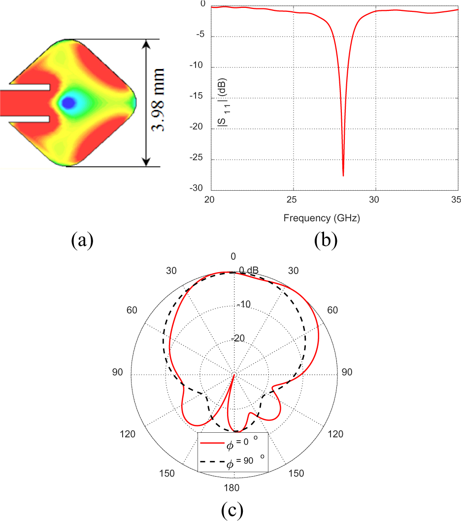
Figure 1: Resonant diamond patch antenna operating at 28 GHz. (a) Surface current distribution and patch dimensions, (b) reflection coefficient , (c) radiation patterns in the two principal and planes at 28 GHz.
At higher frequencies greater than 28 GHz, the designed patch is considered electrically large. This allows the formation of higher order resonant modes with sidelobes and nulls in the radiation pattern and this is not suitable for a mobile handset antenna. The shape of the diamond patch can be modified by removing the conducting surface parts with insignificant current density without affecting the patch performance at 28 GHz. This has the effect of reducing the patch size which in turn allows the formed surface current pattern at higher frequencies to have appropriate distribution for a radiation pattern with accepted shape without nulls.
B. Diamond patch size reduction
By looking at the surface current distribution in Fig. 1 (a), it can be seen that the center of the patch has very low current density. Thus, the metal at the center of the patch can be removed without significantly affecting the patch performance at 28 GHz. A triangular cut is made at the center of the patch as shown in Fig. 2 (a). The patch dimensions are modified to let it resonate at 28 GHz and also the inset length is changed to 1.64 mm. The new modified patch has a 13% reduction in size from the original diamond patch in Fig. 1 (a). The surface current distribution, reflection coefficient, and the radiation pattern of the modified diamond patch are shown in Figs. 2 (a), 2 (b), and 2 (c), respectively. The maximum antenna gain is 5.57 dBi.
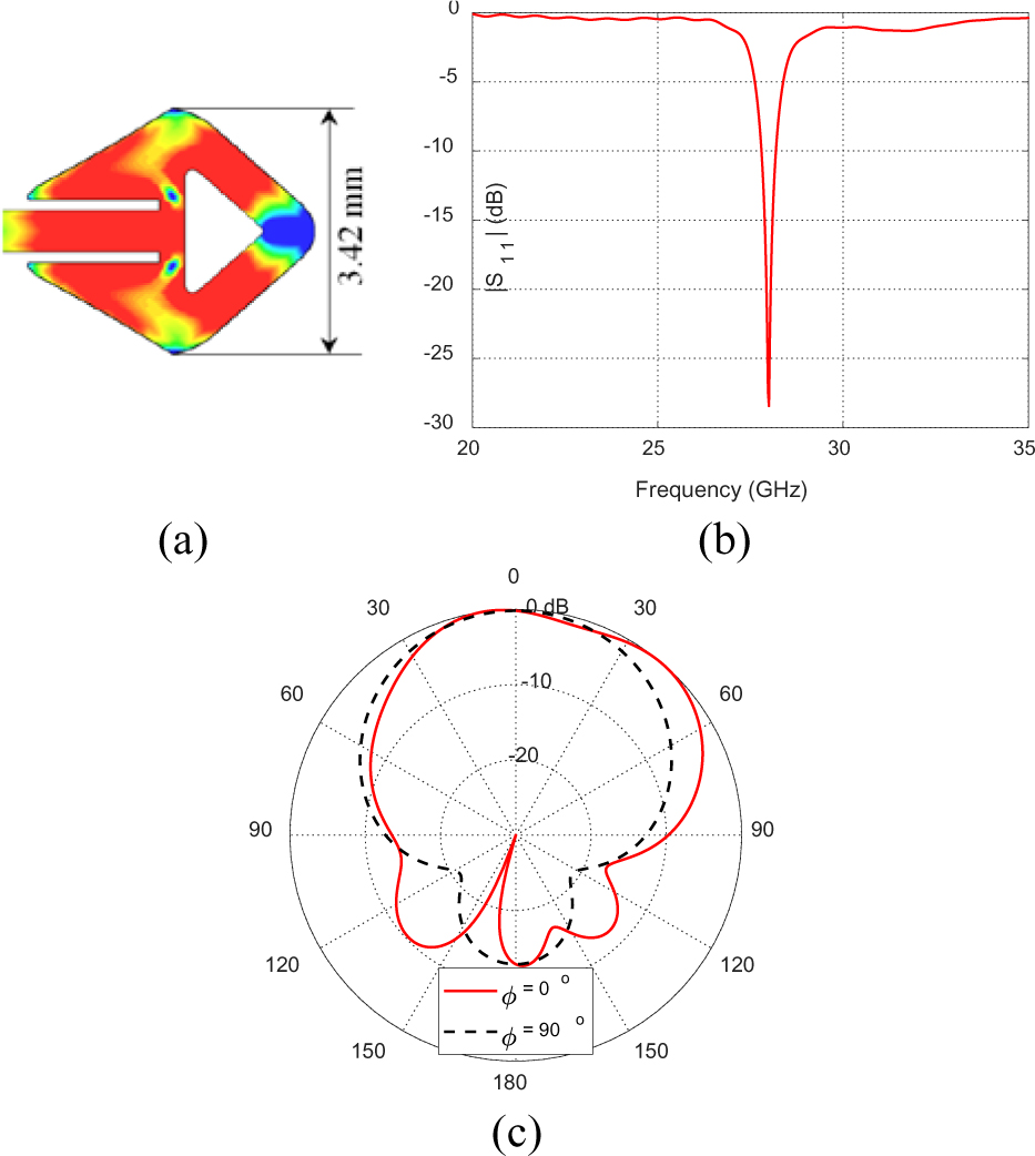
Figure 2: Modified diamond patch antenna with triangular cut at 28 GHz. (a) Surface current distribution and dimensions, (b) reflection coefficient , (c) radiation patterns at 28 GHz.
C. Compact patch design on a defected ground
To further reduce the diamond patch size and in order to get a higher-order resonance at 38 GHz, a crossed-slot defect is made in the ground plane as shown in Fig. 3 (a). The dimensions of the compact patch together with the dimensions of the crossed-slot defect of the ground plane are set to get the higher-order resonance exactly at 38 GHz. Extensive parametric studies have been done through electromagnetic simulation to arrive at the optimal dimensions of the patch and the ground slots to let the structure resonate at 28 and 38 GHz. By comparing the dimension of the original diamond patch and the patch designed on a defected ground, it can be deduced that the patch dimension has been reduced by about 45%. The surface current distribution of the modified diamond patch antenna with DGS is shown in Fig. 3 (a). The reflection coefficient and the elevation radiation patterns at 28 GHz is presented in Figs. 3 (b) and 3 (c), respectively. The maximum antenna gain is 4.39 dBi at 28 GHz. The design of the proposed patch, with its final dimensional parameters, is shown inFig. 4.
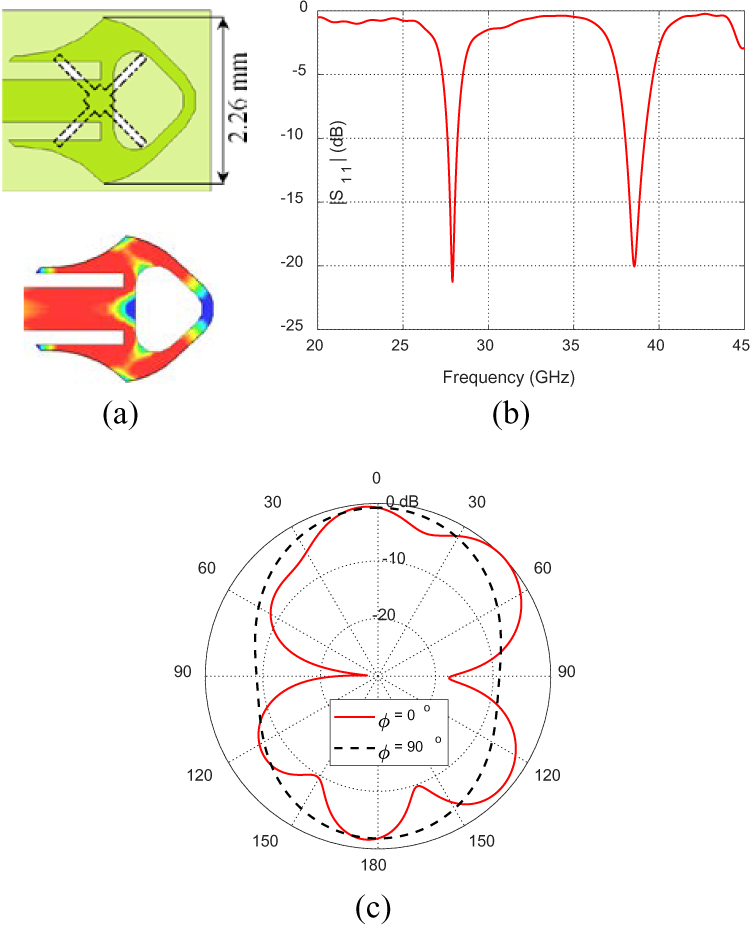
Figure 3: Design of diamond patch antenna with curved corners and triangular cut on DGS. (a) Patch dimensions and surface current distribution, (b) reflection coefficient , (c) elevation radiation patterns at 28 GHz.
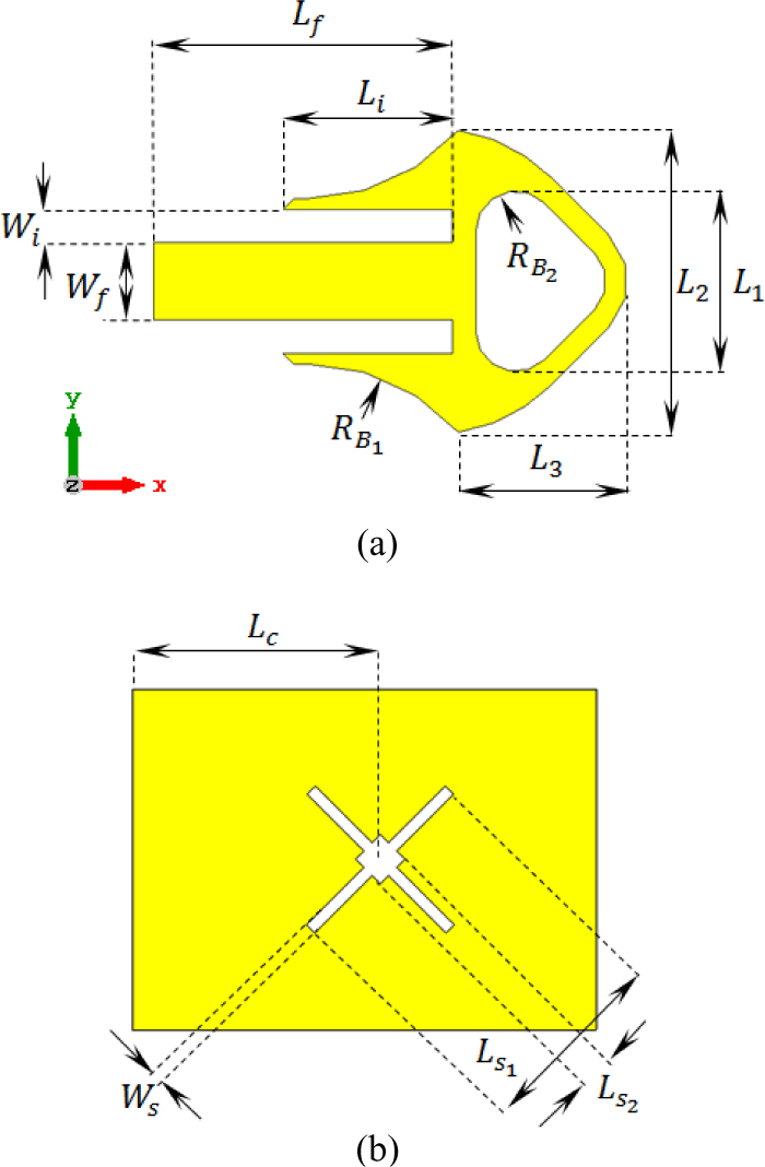
Figure 4: Design and dimensional parameters of the proposed dual-band diamond patch antenna, (a) patch dimensions, (b) DGS dimensions.
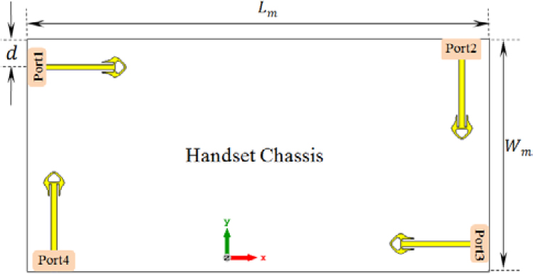
Figure 5: Four-port MIMO antenna system proposed for 5G mobile phones arranged for polarization diversity.
III. MIMO ANTENNA SYSTEM WITH SPATIAL AND POLARIZATION DIVERSITIES
A MIMO antenna system with four ports is constructed from four elements of the proposed dual-band 28/38 GHz diamond patch antenna for the future 5G mobile handsets. It is proposed that the four antennas of the MIMO system are arranged at the corners of the mobile handset with progressive rotational orientations such that the successive elements have orthogonal orientations as shown in Fig. 5. Two antennas are horizontally oriented (directed) whereas the other two antennas are vertically oriented (directed). This arrangement including the orthogonal orientation and the wide separation among the antennas result in both polarization and spatial diversities which are recommended to enhance the communication system performance for the target 5G applications.
Moreover, this MIMO antenna system can produce circular polarization. If the MIMO antenna elements are fed with progressive rotational phase such that the phase shift between the successive elements is degrees, this will produce circular polarization [15, 16].
The reflection and coupling coefficients at the proposed MIMO antenna system ports are investigated together with the resulting radiation patterns in the elevation planes through numerical simulation and experimental measurements.
IV. RESULTS AND DISCUSSIONS
The single element diamond patch antenna as well as the proposed MIMO system performance is studied by numerical simulations and experimental measurements.
A. Dual-band diamond patch antenna simulations and experimental measurements
In this section, the dual-band patch antenna is subjected to performance assessment through electromagnetic simulation as well as experimental measurements of the impedance matching bandwidth and the radiation patterns.
A.1. Operating bands and return loss
The substrate material used in constructing the printed diamond patch antenna is Rogers RO3003C with dielectric constant, dielectric loss tangent , and height . The conducting metal of the upper and lower surfaces of the substrate is made of high conducting copper. The dimensions of the microstrip line that feeds the modified diamond patch is and have a characteristic impedance of . The antenna is fed through and inset to match the source impedance to 50. The final values of the design parameters shown in Fig. 4 are given in Table 1. The fabricated prototype is shown in Fig. 6 (a) compared in size to a one-inch metal coin. A long feeding microstrip line is employed for the ease of measurements. It is clear in the figure that the designed patch is very compact in size. The fabricated antenna prototype is fed using an end-launcher connector from Southwest Microwave Co. as shown in Fig. 6 (b). The fabricated prototype is connected to the vector network analyzer (VNA) from Rhode and Schwartz model ZVA67 as shown in Fig. 6 (c) to measure the dependence of the reflection coefficient, , over a wide frequency band 20-45 GHz. As shown in Fig. 7, the reflection coefficients at 28 and 38 GHz are and dB, respectively. The numerical simulations are verified by experimental measurements showing good agreement. The slight difference between the experimental and simulated results is due to the accuracy of the fabrication process. At 28 GHz, the bandwidth is about 0.6 GHz (), whereas at 38 GHz, the bandwidth is about 1.17GHz (). The radiation efficiencies are 87% and 89.5% at 28 and 38 GHz, respectively.
Table 1: Modified diamond patch final dimensions
| Dimension | |||||||
| Value(mm) | 1.34 | 2.26 | 1.44 | 1.5 | 0.3 | 0.25 | 10.58 |
| Dimension | |||||||
| Value(mm) | 0.62 | 3.46 | 1.27 | 0.58 | 11.15 | 0.2 |
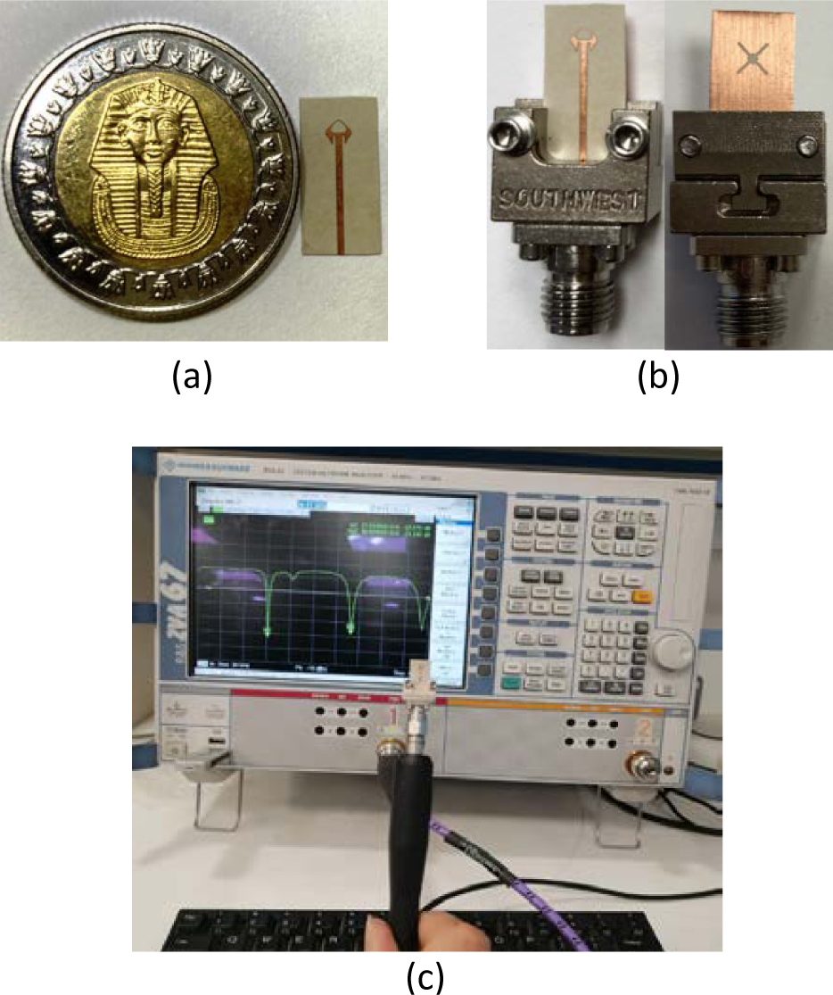
Figure 6: (a) Fabricated prototype compared to a one-inch metal coin, (b) the top and bottom of the fabricated antenna connected to the end-launch connector, (c) the antenna connected to the VNA model ZVA67.
A.2. Radiation patterns of the modified diamond printed antenna
The radiation pattern in the principle elevation planes and is measured experimentally using the setup shown in Fig. 8. A reference antenna model LB-018400 is connected to one port of the VNA ZVA67 and the antenna under test (the modified diamond patch) is connected to the second port. The transmission coefficient between the two ports is measured. The elevation radiation patterns at 28 GHz are shown in Fig. 9. Also, the E-plane and H-plane radiation patterns corresponding to and , respectively, at 38 GHz are presented in Fig. 10. The measured radiation patterns show good agreement with the corresponding radiation patterns obtained through numerical simulations using the commercially available CST package.
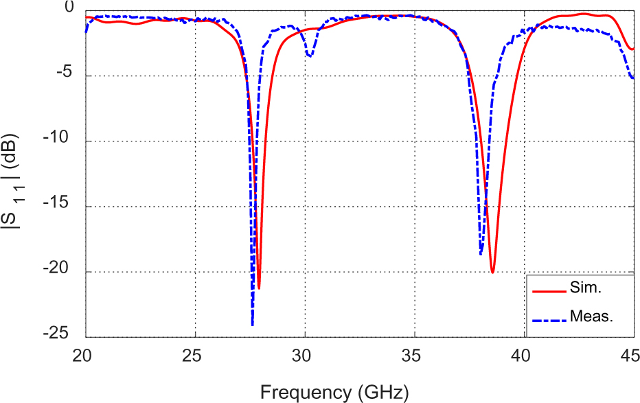
Figure 7: The reflection coefficient dependence on frequency of the proposed diamond patch antenna with the dimensional parameters given in Table 1.
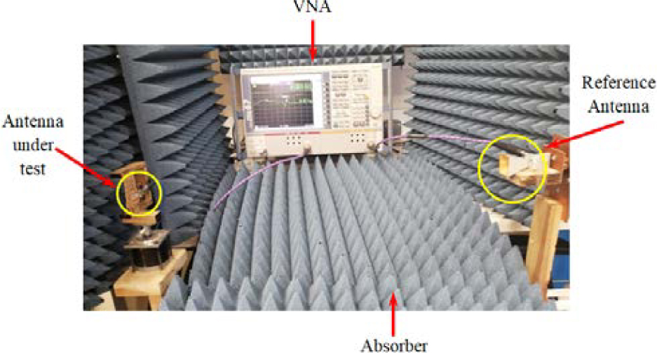
Figure 8: Measurement setup for measuring the radiation patterns experimentally for the proposed modified diamond patch antenna.
B. MIMO antenna system for polarization and spatial diversity
The MIMO antenna system with four ports shown in Fig. 5 is designed to achieve spatial and polarization diversities. It is subjected to performance assessment through electromagnetic simulation as well as experimental measurements. The results are concerned with the mutual coupling among the four ports, ECC, DG, and the radiation patterns.
The four antennas are mounted on a handset antenna mockup as shown in Fig. 11 with , , and . Each antenna has the dimensions listed in Table 1. The handset antenna mockup is shaped like a solid rectangle of overall dimensions . In order to measure the mutual coupling between each two antenna ports in the MIMO system, a 2.4 mm end launch connector is used. The VNA ZVA67 is then employed to measure the transmission coefficient between the two ports. The antenna ports which are not tested are terminated with matched load to prevent any reflections at their ports.
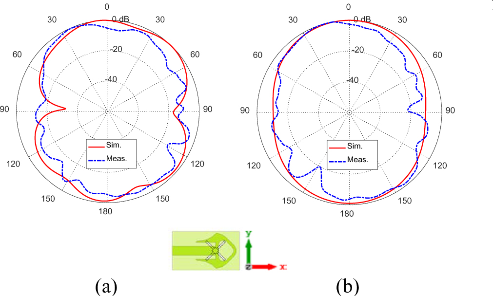
Figure 9: Modified diamond patch radiation patterns at 28 GHz in the principal planes, (a) and, (b) .
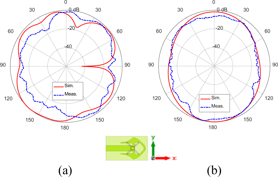
Figure 10: Modified diamond patch radiation patterns at 38 GHz in the principal planes, (a) and, (b) .
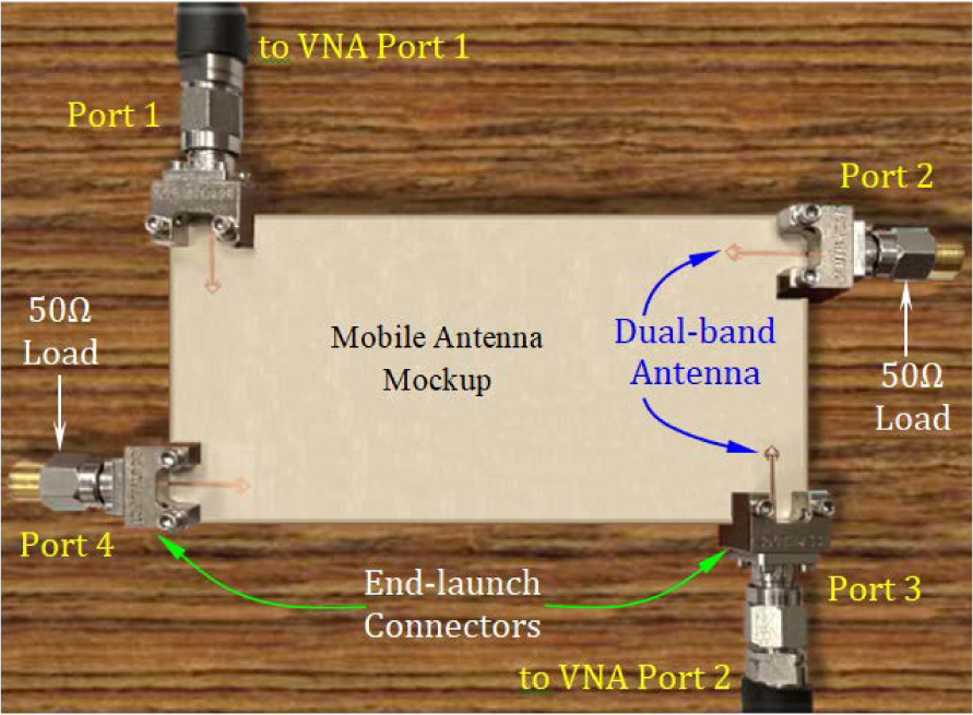
Figure 11: Mobile phone mockup with the proposed modified diamond patches MIMO system.
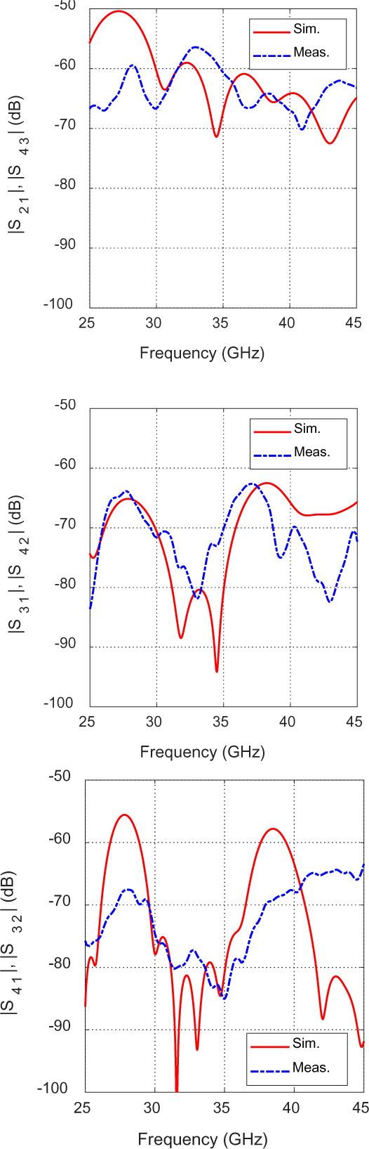
Figure 12: Scattering parameters , , , , , and of the MIMO antenna system constructed from four elements of the proposed modified diamond patch antenna.
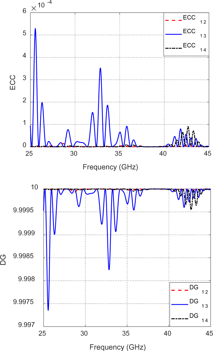
Figure 13: ECC and DG are calculated over a wide frequecny band for the proposed MIMO system constructed from four elements of the modified diamond patch antenna.
B.1. MIMO antenna system performance measurements
The dependence of the scattering parameters , , , , , and on frequency for the proposed MIMO antenna system are obtained through numerical simulations and compared to those obtained experimentally and the results shown in Fig. 12. The experimental results appear to be in agreement with the simulation showing very weak coupling between the MIMOports.
The ECC and the DG are calculated over a wide frequency range 25-45 GHz for the MIMO antenna system ports and the results are illustrated in Fig. 13. The ECC is near zero at the both of the resonant frequency bands 28/38 GHz and the value of the DG is nearly 10. These values are perfect for a MIMO system. The radiation efficiencies of the MIMO antenna system are about 87 % and 90% at 28 and 38 GHz,respectively.
B.2. Radiation patterns of the four-port MIMO antenna system
It should be noted that the term “horizontal polarization” is used to indicate that the electric field is parallel to the (horizontal) whereas the term “vertical polarization” indicates that the electric field is parallel to the (vertical) .
The radiation patterns of the vertically and horizontally polarized fields produced at 28 and 38 by the proposed MIMO antenna system in the planes and , shown in Fig. 3, are presented in Figs. 14–17 when the MIMO antenna system is excited at the different ports. As antenna 1 produces the same polarization as 3, and antenna 2 produces the same polarization as 4, the radiation patterns are demonstrated for antenna 1 and 2 only. It should be noted that the x-direction is designated for the horizontally polarized electric field and the y-direction for the vertically polarized electric field.
For each antenna, the cross-polarization ratio is defined as the ratio between the electric field component in the direction normal to the feeding transmission line and that in the direction parallel to it. For example, at antenna 1, the cross polarization ratio is the ratio between the y-component to the x-component of the electric field. It is shown in Fig. 14 that the radiated field at 28 GHz is mainly horizontally polarized (x-directed) where the cross polarization ratio is about dB in the plane , and about dB in the plane . It is shown in Fig. 15 that the radiated field is horizontally polarized with cross polarization ratio at 38 GHz of about dB in the plane , and dB in the plane . It is shown in Figs. 16 and 17 that the radiated field is mainly vertically polarized. Thus, the above results indicate that the proposed MIMO system has satisfactory performance regarding polarization diversity.
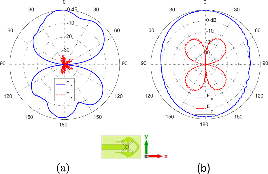
Figure 14: Radiation patterns for the horizontally (x-directed) and vertically (y-directed) polarized fields at 28 GHz in the planes (a) , and (b) when the MIMO antenna system is fed at port 1.
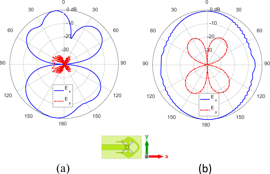
Figure 15: Radiation patterns for the horizontally (x-directed) and vertically (y-directed) polarized fields at 38 GHz in the planes (a) , and (b) when the MIMO antenna system is fed at port 1.
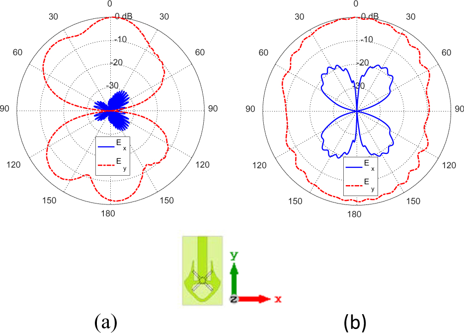
Figure 16: Radiation patterns for the horizontally (x-directed) and vertically (y-directed) polarized fields at 28 GHz in the planes (a) ,and (b) when the MIMO antenna system is fed at port 2.
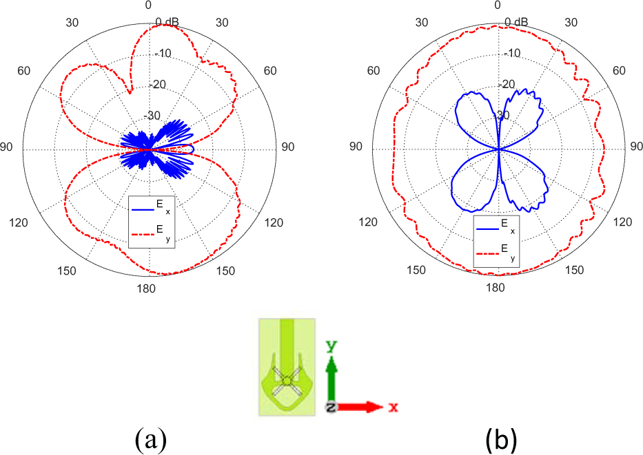
Figure 17: Radiation patterns for the horizontally (x-directed) and vertically (y-directed) polarized fields at 38 GHz in the planes (a) ,and (b) when the MIMO antenna system is fed at port 2.
V. PERFORMANCE COMPARISON WITH PUBLISHED WORK
Comparisons among the dual-band patch antenna proposed in the present work and some other published designs are presented in Table 2. The comparison criteria are the size of the antenna, port isolation, efficiency, and gain.
Table 2: The proposed modified diamond patch compared to published mm-wave antennas
| Work | Center Frequencies (GHz) | Gain (dBi) | Radiation Efficiency (%) | Port Isolation (dB) | Patch Dimensions (mm) |
| [17] | 28/38 | 7/7.3 | 96/95 | 36 | |
| [18] | 28/38 | 3.7/ 5.1 | 83/88 | 25 | |
| [19] | 28/38 | 9.1/9 | 98.3/96.5 | 40 | |
| [Present] | 28/38 | 4.7/3.75 | 88/90 | 50 |
VI. CONCLUSIONS
A novel design of a compact-size modified diamond-shape patch antenna is introduced for dual-band operation at 28/38 GHz. The antenna is constructed as a perforated resonant patch on a defected ground structure (DGS). The evolution stages of the design are described in detail. The patch is inset-fed through a microstrip line. A four-port MIMO antenna system is constructed using the proposed patch antenna. The antennas are arranged at the corners of a mobile handset in orthogonal orientations which results in polarizations and spatial diversities as well as low mutual coupling. The single antenna as well as the MIMO antenna system performance is assessed through numerical simulations and experimental measurements. The scattering parameters including the reflection and coupling coefficients are calculated using the commercially available CST package and measured experimentally showing good agreement. The proposed antenna has a bandwidth of 0.6 GHz at 28 GHz and 1.17 GHz at 38 GHz. To evaluate the performance of the proposed MIMO antenna system, key performance parameters such as the radiation efficiency, envelope correlation coefficient (ECC), and diversity gain (DG) are investigated. The proposed four-port MIMO antenna system configuration is shown to be suitable for polarization and spatial diversity schemes as illustrated from the resulting radiation patterns. The proposed antenna has high radiation efficiency and the MIMO system has very good values for the ECC and DG over the operating frequency bands. The MIMO system possesses good polarization and spatial diversities with good isolation between the antennas without the use of any isolation enhancement techniques.
REFERENCES
[1] A. Mousazadeh and G. H. Dadashzadeh, “A novel compact UWB monopole antenna with triple band-notched characteristics with EBG structure and two folded V-slot for MIMO/diversity applications,” Applied Computational Electromagnetics Society (ACES) Journal, vol. 31, no. 1, pp. 1-7, 2016.
[2] A. E. Farahat and K. F. A. Hussein, “Dual-band (28/38 GHz) MIMO antenna system for 5G mobile communications with efficient DoA estimation algorithm in noisy channels,” Applied Computational Electromagnetics Society (ACES) Journal, vol. 36, no. 3, 2021.
[3] S. Jyoti and S. K. Agarwal, “Design a single band microstrip patch antenna at 60 GHz millimeter wave for 5G application,” In 2017 international conference on Computer, Communications and Electronics (Comptelix), pp. 227-230, IEEE, 2017.
[4] H. Wonbin, K. Baek, and S. Ko, “Millimeter-wave 5G antennas for smartphones: Overview and experimental demonstration,” IEEE Transactions on Antennas and Propagation, vol. 65, no. 12, pp. 6250-6261, 2017.
[5] L. Malviya, R. K. Panigrahi, and M. V. Kartikeyan, “MIMO antennas with diversity and mutual coupling reduction techniques: a review,” International Journal of Microwave and Wireless Technologies, vol. 9, no. 8, pp. 1763-1780,2017.
[6] T. Jiang, T. Jiao, and Y. Li “A low mutual coupling MIMO antenna using periodic multi-layered electromagnetic band gap structures,” Applied Computational Electromagnetics Society (ACES) Journal, vol. 33, no. 3, pp. 305-311,2018.
[7] K. Yu, Y. Li, and X. Liu, “Mutual coupling reduction of a MIMO antenna array using 3-D novel meta-material structures,” Applied Computational Electromagnetics Society (ACES) Journal, vol. 33, no. 7, pp. 758-763, 2018.
[8] M. Abo El-Hassan, A. E. Farahat, and K. F. A. Hussein, “Compact-size Quad-band patch and MIMO antenna system for 5G mobile handsets,” Progress in Electromagnetics Research C, vol. 112, pp. 221-238, 2021.
[9] L. Malviya, R. K. Panigrahi, and M. V. Kartikeyan, “A 2 2 dualband MIMO antenna with polarization diversity for wireless applications,” Progress in Electromagnetics Research C, vol. 61, pp. 91-103, 2016.
[10] C. Y. D. Sim, “Conical beam array antenna with polarization diversity,” IEEE Transactions on Antennas and Propagation, vol. 60, no. 10, 4568-4572, 2012.
[11] X. Li, B. Yu, H. Shen, L. Zhu, and G. Yang, “An 8-port planar UWB MIMO antenna for future 5G micro wireless access point applications,” In 2017 International Applied Computational Electromagnetics Society Symposium (ACES), pp. 1-2, IEEE, 2017.
[12] M. Han and J. Choi, “Dual-band MIMO antenna using polarization diversity for 4G mobile handset application,” Microwave and Optical Technology Letters, vol. 53, no. 9, pp. 2075-2078,2011.
[13] A. Mchbal, N. A. Touhami, H. Elftouh, M. Moubadir, and A. Dkiouak, “Spatial and polarization diversity performance analysis of a compact MIMO antenna,” The 12th International Conference Interdisciplinarity in Engineering, pp. 647-652, 2019.
[14] P. Chaudhary, A. Kumar, and B. K. Kanaujia, “A low-profile wideband circularly polarized MIMO antenna with pattern and polarization diversity,” International Journal of Microwave and Wireless Technologies, vol. 12, no. 4, pp. 316-322, 2019.
[15] U. H. Khan, B. Aslam, J. Khan, M. Nadeem, H. Shahid, M. A. Azam, Y. Amin, and H. Tenhunen, “A novel asterisk-shaped circularly polarized RFID tag for on-metal applications,” Applied Computational Electromagnetics Society Journal (ACES), vol. 31, no. 9, pp. 1035-1042, 2016.
[16] M. Abo El-Hassan, K. H. Awadalla, and K. F. A. Hussein, “Shaped-beam circularly polarized antenna array of linear elements for satellite and SAR applications,” Wireless Personal Communications, vol. 110, no. 2, pp. 605-619, 2020.
[17] F. Alnemr, M. F. Ahmed, and A. A. Shaalan, “A compact 28/38 GHz MIMO circularly polarized antenna for 5 G applications,” Journal of Infrared, Millimeter, and Terahertz Waves, vol. 42, pp. 338-355, 2021.
[18] W. Ahmad and W. T. Khan, “Small form factor dual band (28/38 GHz) PIFA antenna for 5G applications,” 2017 IEEE MTT-S International Conference on Microwaves for Intelligent Mobility (ICMIM), pp. 21-24, IEEE, Mar. 2017.
[19] A. E. Farahat and K. F. A. Hussein, “28/38 GHz Dual-Band Yagi-Uda antenna with corrugated radiator and enhanced reflectors for 5G MIMO antenna systems,” Progress in Electromagnetics Research C, vol. 101, pp. 159-172, 2020.
BIOGRAPHIES

Asmaa E. Farahat received her B.Sc. and M.Sc. in the Department of Biomedical engineering, Faculty of Engineering, Cairo University, 2002 and 2006, respectively. She received the PhD 2012, Ain Shams University. She is currently associate professor at the Department of Microwave Engineering at the Electronics Research Institute. She has work experience in scientific research for about 16 years. She has published more than 30 papers in international, regional and local scientific journals and conferences. She has worked as secondary investigator for three research projects. Her research interests are in the areas of antennas, electromagnetic wave propagation, risk assessment of human exposure to microwave radiation, remote sensing systems, and radar systems.

Khalid F. A. Hussein received his B.Sc., M.Sc. and Ph.D. degrees in the Department of Electronics and Electrical Communications, Faculty of Engineering, Cairo University, 1990, 1995 and 2001, respectively. He is currently a professor at the Department of Microwave Engineering at the Electronics Research Institute. He has work experience in scientific research for more than 29 years. He has teaching experience in engineering colleges in many universities for more than 20 years. He has supervised more than seventy doctoral and master theses. He has published more than 100 papers in international, regional and local scientific journals and conferences. He has served as Head of Microwave Engineering Department at the Electronics Research Institute for up to four years. He has been a member of the Egyptian Space Program (currently the Egyptian Space Agency) for more than eight years. He has worked as Principal Investigator for four research projects and Head of Research Group in four other research projects. He designed and implemented several satellite antennas between prototypes and finished products. He has provided scientific consultations and conducted field measurements related to and conducted field measurements related to the design and distribution of mobile communication base station antennas for good signal coverage in behalf of many Egyptian and international companies. His research interests are in the areas of antennas, electromagnetic wave propagation, risk assessment of human exposure to microwave radiation, optical communications, photonics, quantum computing, radar systems, particularly ground penetrating radar (GPR), synthetic aperture radar (SAR), and remote sensing systems.

M. Abo El-Hassan received her B.Sc., M.Sc., in Communications and Electronic Engineering, Communications Engineering from Menoufa University, Egypt, in 2007 and 2014 respectively. She received the PhD 2020. She is currently researcher at the Department of Microwave Engineering at the Electronics Research Institute. Her current research interests include RFID, areas in Antennas, Chipless tags, SAR, Beam shaping. She has published more than 18 papers in international, regional and local scientific journals and conferences.
ACES JOURNAL, Vol. 37, No. 6, 716–725.
doi: 10.13052/2022.ACES.J.370607
© 2021 River Publishers