Temperature Effects Analysis on Microwave Rectifiers by Field-Circuit Hybrid Multiphysics Simulation
Hongzheng Zeng1, Yaqing Chen1, Chao Zhou1, Yuzhu Tang2, and Xing Chen2
1Key Laboratory of Flight Techniques and Flight Safety, Civil Aviation Flight University of China, Guanghan, Sichuan 618307, China
zeng.h.z@outlook.com, chenyaqingmail@sina.com, zhouchao@cafuc.edu.cn
2College of Electronics and Information Engineering, Sichuan University, Chengdu, Sichuan 610065, China
tyznature@163.com, xingc@live.cn
Submitted On: February 27, 2022; Accepted On: September 23, 2022
Abstract
This work analyzes the temperature effects on microwave circuits by employing a novel field-circuit hybrid multiphysics simulation. Firstly, the multiphysics simulation is implemented by solving the coupled governing equations including Poisson equations, semiconductor transport equations, and thermodynamic equations; then, the multiphysics simulation is incorporated into circuit analysis; finally, the circuit simulation results are integrated into the finite-difference time-domain (FDTD) simulation by equivalent sources. In this manner, a field-circuit hybrid multiphysics simulation method is presented. Taking two different microwave rectifiers operating at S- and C-band as examples, temperature effects are analyzed by the proposed approach. Simulation results are in good agreement with measured values, demonstrating the accuracy and applicability of the proposed approach. The presented method more suitably reveals the temperature effects on the rectifier.
Index Terms: field-circuit hybrid simulation, multiphysics, Schottky diode rectifier, temperature effects.
1 INTRODUCTION
It is well known that temperature has a major impact on the performance of semiconductor devices and circuits. This is attributable to the fact that temperature changes the effective carrier density, electron and hole mobility, and material properties of semiconductor devices, thereby affecting the performance of the entire circuit [1].
With the development of wireless power transmission, research on microwave rectifiers has attracted considerable attention as a key component of converting space electromagnetic energy into DC. Thereby, the temperature effects caused by the injection of high-power microwave energy into the rectifier cannot be ignored. The accurate and efficient simulation of the temperature effects requires solving more challenging multiphysics problems [1–3]. Currently, multiphysics simulation of semiconductor devices has become a reality. Since multiphysics simulation can better describe the operation of semiconductor devices under various conditions and more accurately predict their physical effects, the multiphysics analysis of semiconductor devices and circuits has received increasing attention in recent years [2]. Abundant research on the electrothermal behaviors of semiconductor devices and circuits, characterized by combining multiple physical equations including electromagnetic fields, semiconductor transport, and thermodynamics, is already available [3–6]. However, the multiphysics simulation of semiconductor devices is very complicated and time-consuming. Considering the significant time and memory requirement, even for the next-generation computer systems, it is almost impossible to accomplish the temperature analysis of entire microwave circuits [7].
So far, research works on temperature effect simulation of the whole microwave circuit are very rare. In general, microwave circuits could be analyzed using either frequency- or time-domain full-wave simulation method [8]. However, in dealing with nonlinear semiconductor devices, time-domain methods enjoy the advantage of allowing for the direct analysis of field-circuit interactions without resorting to harmonic balance or port extraction methods [9]. Since FDTD method remains a popular choice for solving many electromagnetic problems, because of its versatility and ability for dealing with complex geometries, materials, and environments [10–12]. Thus, in the authors’ previous work, a physical model-based field-circuit hybrid simulation method was proposed, and a good agreement between rectifier simulation and measurements was obtained. However, the temperature effects on the microwave rectifier were not taken into account in order to simplify the simulation process [13]. Since microwave rectifiers usually work under high frequency and/or large signals, the temperature effects cannot be ignored. Therefore, the presented research extends previous work by coupling the multiphysics simulation of semiconductor devices to field-circuit hybrid simulation based on FDTD. To this end, the multiphysics simulation is implemented by solving the coupled governing equations including Poisson equations, semiconductor transport equations, and thermodynamic equations; then the multiphysics simulation is incorporated into circuit analysis; finally, the circuit simulation taking into account multiphysics is coupled to FDTD simulation by equivalent sources. In this manner, this paper presents a hybrid field-circuit multiphysics simulation approach. The presented simulation approach is applied to analyze the temperature effects of microwave rectifiers operating at S- and C-band frequencies and a series of experiments are conducted to validate the approach.
This approach not only characters the behaviors of microwave rectifiers under large signal conditions but also predicts its temperature effects. A further obvious advantage is that the hybrid solution scheme reduces the computational burden significantly, enabling system-level circuit simulation and analysis of temperature effects.
2 THE HYBRID FIELD-CIRCUIT SIMULATION APPROACH BASED ON MULTIPHYSICS
The size of semiconductor chips is on the micro- or nano-scale, while the size of device packages and microwave circuits may be on the millimeter scale or larger. Assuming the FDTD field-circuit simulation adopts the unified grid discretization, then the required calculations resources are prohibitively large to accomplish the simulation. While the field-circuit simulation based on an equivalent source can easily integrate the equivalent circuits simulation into full-wave FDTD simulation, greatly reducing the computational burden. Therefore, in order to address the temperature effect analysis problem of microwave rectifiers, this paper couple multiphysics simulation of the semiconductor device to the circuit simulation, and integrate them into the FDTD simulation by equivalent sources, presenting a more accurate and effective hybrid simulation approach. This section provides an introduction to the multiphysics simulation of semiconductor devices and their coupling with circuits, as well as the field-circuit hybrid multiphysics simulation based on equivalent sources.
2.1 Multiphysics analysis and simulation for semiconductor devices
The physical model of semiconductor devices is established based on the geometrical structure and manufacturing process and represented by parameters such as the device’s junction width, gate length, channel thickness, etc. Semiconductor devices are often thermally sensitive, and multiphysics simulations that include temperature effects more accurately model carrier transport and characterize device behaviors.
For numerical analysis of semiconductor devices, a series of low-order approximate equations can be derived from electromagnetic field theory and semiconductor physics. Among them, the drift-diffusion model (DDM) is the most widely used semi-classical model. Up until now, DDM successfully simulate the semiconductor carrier transport phenomenon under non-isothermal conditions, thereby basic equations are Poisson Equation, current continuity equation, and drift-diffusion equation [14, 15]:
| (1) | ||
| (2) | ||
| (3) |
| (4) | ||
| (5) |
where and denote the material permittivity, electronic chargeand electrostaticpotential, respectively; , and denote the doping, electron and holes density, respectively. and denote carriers generation rate and recombination rate, respectively. and denote the electron and the hole current density, respectively; , and denote the temperature, Boltzmann constant, electron and hole mobility, respectively [1].
To analyze the temperature effects on semiconductor performance in microwave power circuits, in addition to DDM, the multiphysics simulation of semiconductor devices should contain the heat conduction equation and equations containing temperature-dependent characteristic parameters [16]:
| (6) | |
| (7) | |
| (8) | |
| (9) | |
| (10) |
where and are the material density and the thermal conductivity, respectively; is the heat generated per unit time and volume, and is the electric field and band-gap width of diode, respectively; and are effective state densities of the conduction band bottom and valence band top, respectively; and are the effective mobility and the lifetime of electrons and holes at ambient temperature, respectively; is the critical field;; and are empirical constant [14].
The multiphysics equation system consists of Eqs. (1)–(10) and is a coupled nonlinear partial differential equation system. In fact, it is impossible to give a closed-form solution, thereby an iterative numerical method is employed to solve this system equations.
It can be seen that the main unknowns in the multiphysics equation system are: and . Without loss of generality, taking one-dimensional space as an example, the device grid division is shown in Fig. 1.
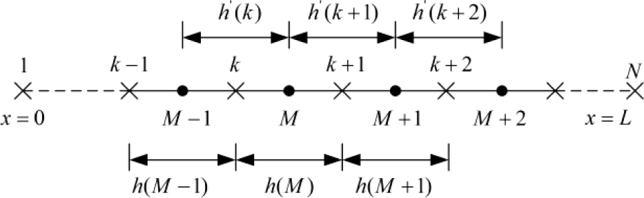
Figure 1: The one-dimensional difference grids of semiconductor devices.
When T is a known value, The electrical characteristics Eqs. (1)–(5) are discretized by central difference and linearize [17], the whole procedure can be simplified to the solution of an increment equation [18]:
| (11) |
where coefficient matrices; H is a coefficient matrices. coefficient matrices value are described in [16].
When and are known values, the heat conduction Eq. (6) may be discretized into first-order ordinary time-dependent differential equations [18]:
| (12) |
where and are the discretization coefficients. By using the Newton-Raphson iteration method,(12) can be can be rewritten as an increment equation:
| (13) |
where a, b, c, and h are the coefficients. Eqs. (11) and (13) can also be solved by using the chasing method, and the true values of , and T can be obtained after many iterations [19].
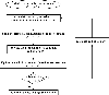
The iterative procedure for the multiphysics simulation of the semiconductor model is shown in Fig. 2. Firstly, the physical parameters of the semiconductor device are calculated by the initial electrical and temperature parameter (the carrier mobility generation and recombination rate etc.) and the semiconductor devices are solved by introduced electrical Eqs. (1)-(5). Then the heat conduction Eq. (6) and (7) are solved by the electric field, current, and other parameters to obtain the temperature, the electrical parameters are updated based on the current temperature and obtain the electrical field and temperature until it converges. Finally, the device voltage and current is calculated.
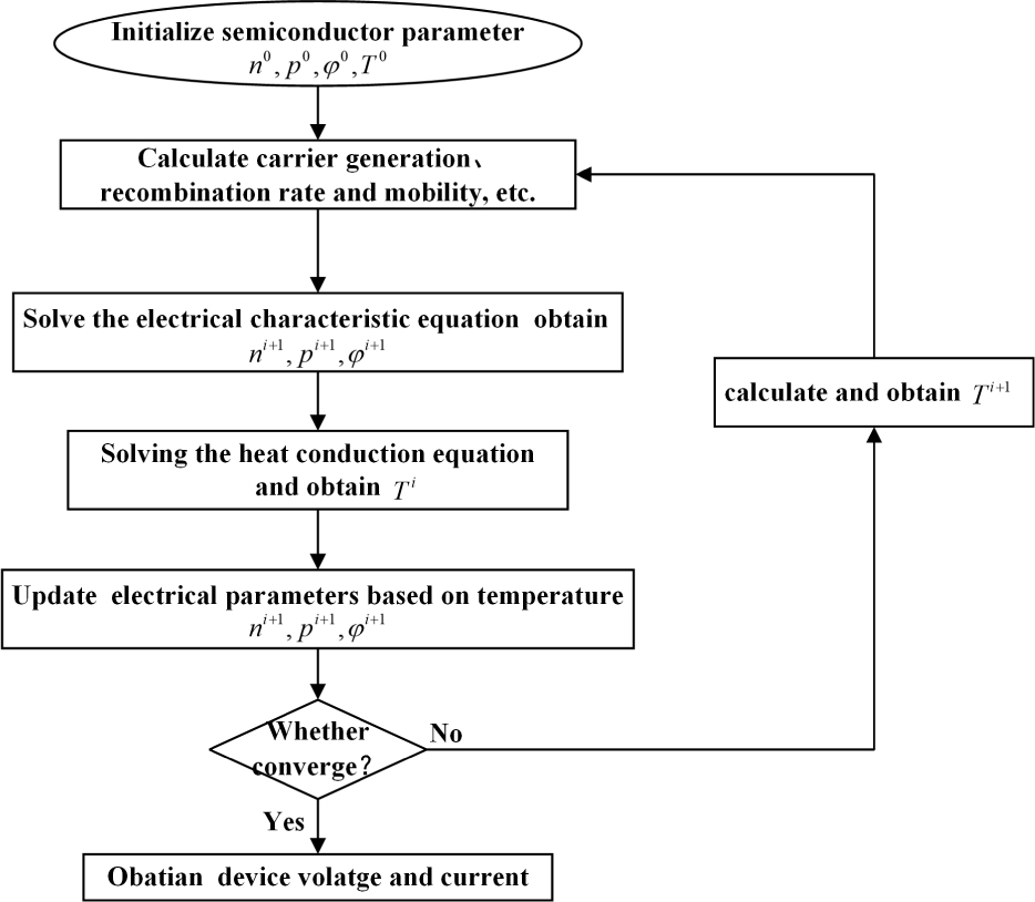
Figure 2: Brief flow chart for multiphysics simulation of semiconductor device.
2.2 Integrating multiphysics simulation of semiconductor devices into circuit analysis
The circuit analysis is an indispensable part for conventional field-circuit hybrid simulation, which needs to integrate the equivalent circuit simulation into FDTD by equivalent sources. According to circuit analysis theory, circuit simulation can be rewritten as a system of equations by an improved nodal analysis method [20]:
| (14) |
Here is the index of the unknown node voltage, is the unknown value, is the node voltage equation. The solution procedure of the nonlinear(14) is converted to the Newton-Raphson iterative equations:
| (15) |
where .
the node voltage equation:
| (16) |
For any semiconductor device in the circuit, assuming the device is located in the j-th branch, and two adjacent nodes are (k-1) and k, the nonlinear relationship between the branch current and the terminal voltage can be expressed as [20]:
| (17) |
To obtain transient response of the circuit, the diode branch current Eq. (17) is obtained by the multiphysics simulation, introduced previously. while the branch currents of other linear devices are derived from the circuit simulation based on its constitutive equations. In this way, the multiphysics and the circuit simulation are integrated into a unified scheme.
2.3 Field-circuit hybrid multiphysics simulation based on equivalent sources
In numerical simulation of antennas and microwave circuits based on FDTD, the current through the lumped element can be regarded as an additional current term in the Maxwell’s integral equations [21]:
| (18) |
| (19) |
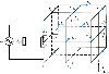
where represents the current flowing through the semiconductor device. The Eqs. (18) and (19) can be easily convert to differential forms, and discrete by FDTD Yee grid. Since physical sizes of semiconductor devices are generally much smaller than the minimum wavelength of the operating frequency, it could be modeled by one dimension, and only occupied one or several serial Yee grid under the uniform FDTD framework, as shown in Fig. 3.
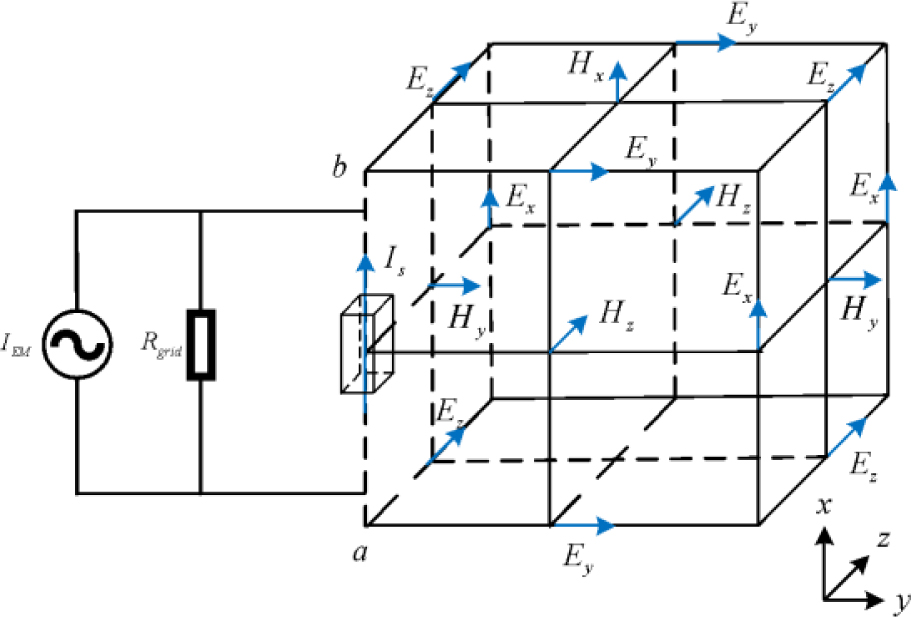
Figure 3: Discrete form of Yee grid containing semiconductor devices.
Without loss of generality, in Fig. 3, assume a semiconductor device is located between nodes a and b, The terminal voltage of the semiconductor device can easily be derived from the electric field through path integral [21]:
| (20) |
A control equation can be derived by combining with Eqs. (18)-(20):
| (21) |
In which [21]:
| (22) | ||
| (23) | ||
| (24) |
According to circuit analysis, the form of Eq. (21) can be interpreted as a controlled current source in parallel with an equivalent resistance. Where is deduced from the electromagnetic field value of the previous time step, is an equivalent resistance that calculated from FDTD grid size [21]. The FDTD field-circuit scheme along the y, z direction is similar, its implicit form ensures simultaneous calculation of the electric field (deduced from voltage) and current, resulting in the simulation method having a higher stability.
Microwave circuits containing semiconductor devices are generally considered to be a hybrid system and can be simulated using a field-circuit hybrid method based on equivalent sources [22]. Generally, the equivalent sources first equate the electromagnetic field effect on the semiconductor devices as lumped circuits, and then solves the circuits formed by the connection between the equivalent source and the lumped circuit, finally converting the obtained voltage or current to the electric or magnetic field value.
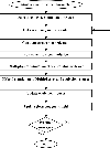
In our proposed field-circuit hybrid multiphysics simulation method, the equivalent circuits of semiconductor devices are substituted by multiphysics modeling and simulation; then, the multiphysics simulation of semiconductor devices is coupled with circuit analysis, and integrate into FDTD full-wave simulation. The transient simulation of the entire circuit system is implemented by advancing synchronously and exchanging data within each FDTD time step, as shown inFig. 4.
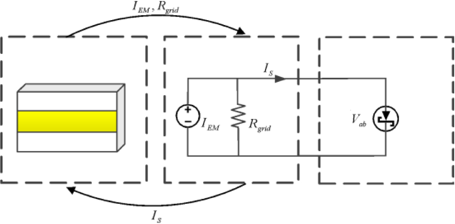
Figure 4: The coupling relationship of multi-physics field.
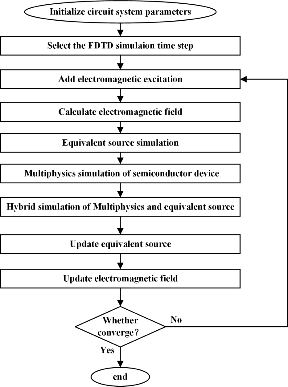
Figure 5: The flow chart of field-circuit hybrid multiphysics Simulation.
It is important to emphasize that the initial state of the circuit transient analysis needs to be set to the end state, especially the state of the semiconductor device (including electric field, carrier density distribution, and mobilities, temperature, etc.) at the previous time step. This is especially essential for accurate and effective analysis of the whole system. A brief flow chart is shown in Fig. 5.
3 SIMULATION AND EXPERIMENT
Silicon-based diodes of the HSMS-282x series are widely used in microwave rectifiers, featuring low costs and good RF characteristics. It is composed of thin epitaxial layers deposited on heavily doped substrates, with Schottky contacts at the anode and ohmic contacts at the cathode [13].
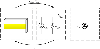
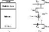
To reduce the simulation burden, we make a one-dimensional simplification with maintaining the diode characteristics, and its inner structure is shown in Fig. 6 (a) [23]. In this figure, Schottky barrier height and metal work function are denoted by and , respectively; the doping concentration of epitaxial layer and substrate are indicated by and , respectively; the length of epitaxial layer and substrate are indicated by and , respectively; the effective contact area of the diode is denoted by . For microwave frequency applications, the diode package effect cannot be ignored. Schottky diodes of HSMS-282x series adopt SOT-323 package size, the package effect could be characterized by the equivalent circuit shown in Fig. 6 (b), which is suitable up to 6 GHz. In Fig. 6 (b), and are lead capacitors, respectively; is the package capacitor; and are the welding inductance and lead inductance, respectively.
The physical model and package parameters of Schottky diode HSMS-282 and HSMS-286 have been extracted in the authors’ previous work, they are listed in Table 1 and Table 2 respectively for easy reference [13].
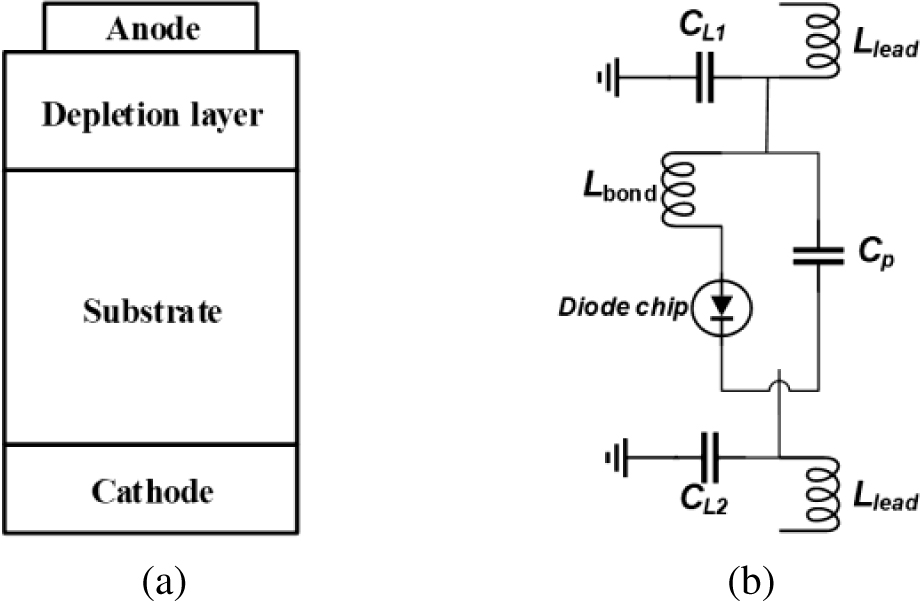
Figure 6: Physical model parameters of Schottky diodes: (a) the structure of Schottky diode, (b) the package equivalent circuit.
The MW-to-DC power conversion efficiency (PCE) is a key indicator to measure the performance of microwave rectifiers [24]. Generally, PCE of the rectifier could be calculated by the following formula:
| (25) |
where and are the microwave input Power and DC output power, respectively; and are the output DC voltage and load, respectively [24].
To verify the accuracy and applicability of the proposed method in simulating the temperature effects of microwave circuit, taking two different microwave rectifiers operating at S- and C-band as examples, the simulations are performed by presenting a field-circuit hybrid multiphysics approach under different ambient temperatures (25 , 75 ). The simulation program is executed on a computer workstation with a 3.4GHz frequency Intel Core CPU, 32GB memory and 64-bit Windows operating system. Furthermore, two rectifiers are placed into a well-sealed thermostat, and the conversion efficiency is measured to validate the simulation results.
Table 1: Physical parameters of two Schottky diodes
| Parameters | HSMS-282 | HSMS-286 |
|---|---|---|
| [V] | 0.629 | 0.568 |
| [V] | 4.679 | 4.631 |
| [m] | 5.4410 | 2.9110 |
| [m] | 210 | 210 |
| [m] | 0.97 | 1.327 |
| [m] | 1.02 | 1.33 |
| [cm] | 610 | 5.6110 |
Table 2: Package parameters of two Schottky diodes
| Parameters | HSMS-282 | HSMS-286 |
|---|---|---|
| [pF] | 0.16 | 0.2 |
| [nH] | 0.79 | 0.525 |
| [nH] | 0.86 | 0.98 |
| [pF] | 0.007 | 0.02 |
| [pF] | 0.002 | 0.08 |
3.1 The temperature effects analysis on S-band microwave rectifiers
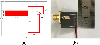
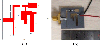
A compact S-band microwave rectifier working at a frequency of 2.45 GHz has been manufactured by utilizing the HSMS-282B diode. The type of printed circuit board (PCB) used in the rectifier is F4B-2 with a relative dielectric constant of 2.65, a loss tangent of 0.0012 and a thickness of 1 mm. The manufactured rectifier dimension is 20 mm 16 mm; its structure and photograph are shown in Fig. 7 (a) and (b), respectively.
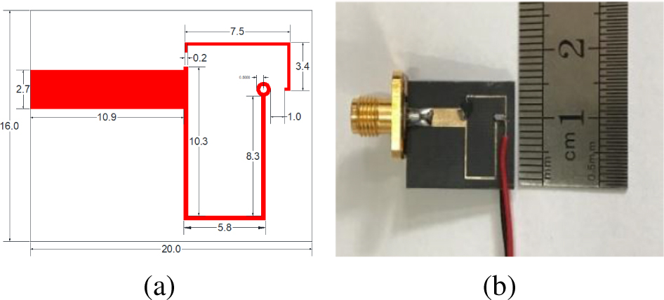
Figure 7: (a) Schematic diagram of the 2. 45 GHz rectifier; (b) Photograph of manufactured 2. 45 GHz rectifier.
It is known that the rectifier performance is determined by the entire circuit structures, including input matching and output filtering. However, as a nonlinear device, the Schottky rectifier diodes always generate high-order harmonics. Although the output filters only allow DC to pass through and reflects the fundamental frequency and harmonics, there are still a few harmonics superimposed on the DC output to cause a ripple.
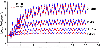
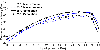
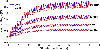
For the S-band rectifier, the computational domain is uniformly divided into 24019032 (including 5-layer air and 10-layer CPML) grids in the x, y, and z directions, the number of iterations is 55000, each iteration time is approximately 8.4 s, the total simulation time is about 128.3 hours. Here, several typical simulated output voltages of the rectifier at different ambient temperatures are given in Fig. 8. The simulated and measured PCE under different temperature (25 , 75 ) are shownin Fig. 9.
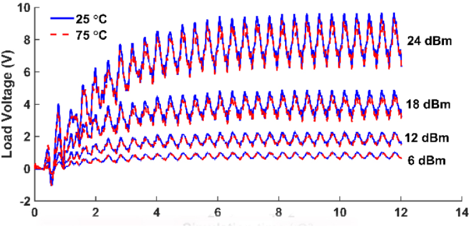
Figure 8: Several typical output voltages of S-band rectifier at different ambient temperatures.
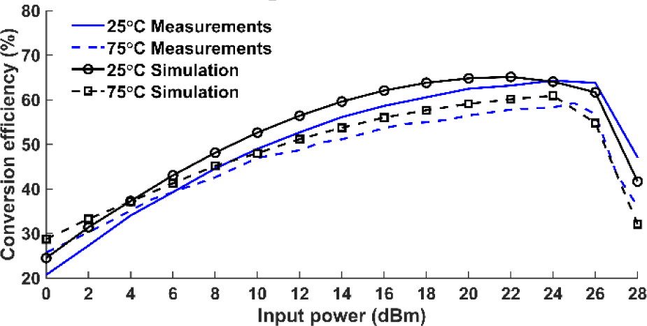
Figure 9: PCE of S-band rectifier simulation and measurements at different ambient temperatures.
3.2 The temperature effects analysis on C-band microwave rectifiers
A C-band rectifier was manufactured working at frequency 5.8 GHz by utilizing the HSMS-286B diode, which still adopts the same PCB as the above-mentioned S-band microwave rectifier. The manufactured rectifier dimension is 20 mm 30 mm, its structure and photograph are shown in Fig. 10 (a) and (b), respectively.
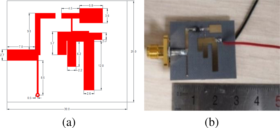
Figure 10: (a) Schematic diagram of the 5. 8 GHz rectifier; (b) Photograph of manufactured 5. 8 GHz rectifier.
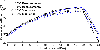
For the C-band rectifier, the computational domain is uniformly divided into 28028022 (including 5-layer air and 10-layer CPML) grids in the x, y, and z directions, the number of iterations is 35000, each iteration step is approximately 9.6 s, the total simulation time is about 93.3 hours. The typical output voltages of C-band rectifier at different ambient temperatures (25 , 75 ) are simulated, and shown in Fig. 11. The simulated and measured PCE under different temperature are shown in Fig. 12.
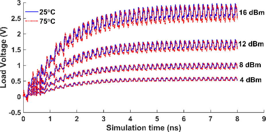
Figure 11: Several typical output voltages of C-band rectifier at different ambient temperatures.
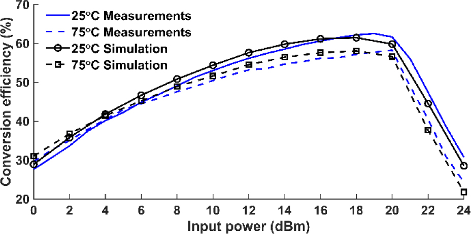
Figure 12: PCE of C-band rectifier simulation and measurements at different ambient temperatures.
From Figs. 9 and 12, it can be clearly seen that both S-band and C-band Schottky rectifiers, the PCE have a consistent variation trend with temperature. The slight errors may attribute to the discontinuities of SMA connectors and temperature effects on PCB material properties. The PCE increases slightly with temperature increase under low input power, yet decreases significantly with temperature increase under high input power. From a physical point of view, that is due to the fact that the Schottky diode is a cut-off state under low input power, carrier density of the Schottky diode increase with temperature rise, which causes diode current aggrandize and makes the PCE gradually increase. However, as the input power continually increases, the Schottky diode becomes a turn-on state, the diode impedance diminution with the temperature rise, which will lead to the input and output impedance mismatch and make the PCE decrease significantly.
The measured results are validated by the simulation results at different temperatures, which confirm the effectiveness and applicability of our proposed approach.
Furthermore, excessive input power may cause Schottky diode self-heating, resulting in power conversion efficiency decrease. Thus, power conversion efficiency of rectifiers can be optimized by carefully selecting suitable temperature conditions, especially for energy harvesting application at a low input power level.
4 CONCULSION
The temperature effects of electronic devices and circuits are essential for microwave power application. This paper adopts a novel field-circuit hybrid multiphysics simulation to analyse the temperature effects of microwave rectifier. Firstly, multiphysics model involving semiconductor and thermal conducting is solved; then, multiphysics simulation is embedded into circuit analysis; finally, this circuit analysis was coupled into field-circuit hybrid simulation based on FDTD. Taking two different Schottky diode rectifiers operating at S- and C-band as examples, simulation results match well with the measured ones, which validate the accuracy and applicability. This method that combines the multiphysics simulation and FDTD solution can greatly improve the simulation accuracy of microwave power circuits. This approach not only has the advantage of accuracy and versatility stemming from the multiphysics simulation, but also retains simplicity and efficiency of the FDTD field-circuit hybrid simulation.
Moreover, the propose method effectively reveal the physical mechanism of rectifier temperature effects. Furthermore, the presented approach could be extended to more complex circuits without significant modifications. This method may become an attractive candidate for simulating and predicting temperature effects of microwave power circuits.
ACKNOWLEDGEMENT
This work is supported by Flight Efficiency Improvement Research Center (No. JG2022-09) of Civil Aviation Flight University of China, Funding Program of CAFUC (No. ZX2021-03), and National Key R&D Program of China (No. 2018YFC0809500).
REFERENCES
[1] S. M. Sze, Y. Li, and K. K. Ng, Physics of Semiconductor Devices, John Wiley & Sons, 2021.
[2] J.-M. Jin and S. Yan, “Multiphysics modeling in electromagnetics: Technical challenges and potential solutions,” IEEE Antennas Propag. Mag., vol. 61, no. 2, pp. 14-26, 2019.
[3] M. Riccio, G. De Falco, P. Mirone, L. Maresca, M. Tedesco, G. Breglio, and A. Irace, “Accurate spice modeling of reverse-conducting IGBTs including self-heating effects,” IEEE Trans. Power Electron., vol. 32, no. 4, pp. 3088-3098, Apr. 2017.
[4] N. Lin and V. Dinavahi, “Dynamic electro-magnetic-thermal modeling of MMC-based DC-DC converter for real-time simulation of MTDC grid,” IEEE Trans. Power Del., vol. 33, no. 3, pp. 1337-1347, Jun. 2018.
[5] T. Pan, D. Ding, H. Li, and X. Cheng, “Transient electro-thermal analysis of a common source amplifier circuit with a physics-based MOSFET model,” Appl. Comput. Electrom., vol. 34, no. 7, 2019.
[6] A. Tsibizov, I. Kovacevic-Badstubner, B. Kakarla, and U. Grossner, “Accurate temperature estimation of SiC power MOSFETs under extreme operating conditions,” IEEE Trans. Power Electron., vol. 35, no. 2, pp. 1855-1865, Feb. 2020.
[7] H. H. Zhang, P. P. Wang, S. Zhang, L. Li, P. Li, W. E. Sha, and L. J. Jiang, “Electromagnetic-circuital-thermal multiphysics simulation method: a review,” Prog. Electromagn. Res., vol. 169, pp. 87-101, 2020.
[8] Q. Zhan, Y. Wang, Y. Fang, Q. Ren, S. Yang, W.-Y. Yin, and Q. H. Liu, “An adaptive high-order transient algorithm to solve large-scale anisotropic Maxwell’s equations,” IEEE Trans. Antennas Propag., vol. 70, no. 3, pp. 2082-2092, 2021.
[9] E. K. Miller, “Time-domain modeling in electromagnetics,” J. Electromagnet. Wave, vol. 8, no. 9-10, pp. 1125-1172, 1994.
[10] G. Xu, X. Chen, Z. Zheng, and K. Huang, “A hybrid FDTD-SPICE method for the analysis of microwave circuits,” Int. J. Appl. Electrom., vol. 49, no. 1, pp. 79-90, 2015.
[11] X. Wang, L. Wang, J. Zhuo, X. Lu, M. Yuan, J. Zhou, and Q. H. Liu, “A hybrid CN-FDTD-SPICE solver for field-circuit analyses in low-frequency wideband problems,” IEEE Trans. Compon. Packag. Technol, vol. 10, no. 10, pp. 1721-1728, 2020.
[12] Y. Wang, J. Wang, L. Yao, and W.-Y. Yin, “EMI analysis of multiscale transmission line network using a hybrid FDTD method,” IEEE Trans. Electromagn. Compat., vol. 63, no. 4, pp. 1202-1211, 2021.
[13] H. Zeng, Y. Tang, X. Duan, and X. Chen, “A physical model-based FDTD field-circuit co-simulation method for Schottky diode rectifiers,” IEEE Access, vol. 7, pp. 87265-87272,2019.
[14] K. Xu, X. Chen, and Q. Chen, “Non-quasi-static effects simulation of microwave circuits based on physical model of semiconductor devices,” Appl. Comput. Electrom., pp. 992-998, 2020.
[15] K. Xu, X. Chen, and Z. Chen, “A physics-based transient simulation and modeling method for wide-frequency electrical overstress including ESD,” Appl. Comput. Electrom., pp. 505-512, 2021.
[16] S. Selberherr, Analysis and Simulation of SemiConductor Devices, Springer Science & Business Media, 2012.
[17] G. Sun and C. W. Trueman, “Efficient implementations of the Crank-Nicolson scheme for the finite-difference time-domain method,” IEEE Trans. Microw. Theory Tech., vol. 54, no. 5, pp. 2275-2284, 2006.
[18] J. Q. Chen, X. Chen, C. J. Liu, K. Huang, and X. B. Xu, “Analysis of temperature effect on pin diode circuits by a multiphysics and circuit cosimulation algorithm,” IEEE Trans. Electron Devices, vol. 59, no. 11, pp. 3069-3077, 2012.
[19] D. Poole, Linear Algebra: A Modern Introduction, Cengage Learning, 2014.
[20] X. Chen, J. Q. Chen, K. Huang, and X.-B. Xu, “A circuit simulation method based on physical approach for the analysis of Mot_bal99lt1 pin diode circuits,” IEEE Trans. Electron Devices, vol. 58, no. 9, pp. 2862-2870, 2011.
[21] W. Sui, Time-domain Computer Analysis of Nonlinear Hybrid Systems, CRC Press, 2018.
[22] H. Zeng, and X. Chen, “Nonlinear analysis for microwave limiter using a field-circuit simulator based on physical models,” IEEE Microw. Wireless Compon. Lett., vol. 30, no. 2, pp. 129-132,2020.
[23] H. Wang, X. Chen, G. H. Xu, and K. M. Huang, “A novel physical parameter extraction approach for Schottky diodes,” Chin. Phys. B, vol. 24, no. 7, Jul. 2015.
[24] C. Liu, F. Tan, H. Zhang, and Q. He, “A novel single-diode microwave rectifier with a series band-stop structure,” IEEE Trans. Microw. Theory Tech., vol. 65, no. 2, pp. 600-606, 2016.
BIOGRAPHIES

Hongzheng Zeng received an M.S. degree from Chongqing University of Posts and Telecommunications, China, in 2014, and a Ph.D. degree in Radio Physics at Sichuan University, China, in 2020. Presently, he is the Research Associate with Key Laboratory of Flight Techniques and Flight Safety, Civil Aviation Flight University of China. His research interests include numerical methods applied in electromagnetics, microwave circuits simulation, and electromagnetic environmental effect.

Yaqing Chen received an M.S. from Southwest Jiaotong University, China, in 2005. Presently, he is a professor and executive deputy director of the Key Laboratory of Civil Aviation Flight Technology, at Civil Aviation Flight University of China. His research interests include general aviation operations and safety, and air traffic management. Professor Chen is the member of civil aviation science and technology committee, and the academic and technical leader candidate in Sichuan province, China.

Chao Zhou a received an M.S. from Southwest Jiaotong University, China, in 2002, and a Ph.D. degree from University of Electronic Science and Technology University, China, in 2013. Presently, he is a professor at Civil Aviation Flight University of China. His research interests include civil aviation electromagnetic environmental effects and unmanned aircraft systems. Professor Zhou is the visiting researcher fellow of Chengdu Computing Institute of China Commercial Aircraft, and the academic and technical leader candidate in Sichuan province, China.

Yuzhu Tang a received his B.S. in communication engineer in 2012 from University of Electronic Science and Technology and M.S. from Chengdu University of Information Engineering, China, in 2017. Currently, he is pursuing his Ph.D. in radio physics at Sichuan University. His research is mainly focused on microwave active circuits and antenna.

Xing Chen a received an M.S. degree in radio physics and the Ph.D. degree in biomedical engineering from Sichuan University, Sichuan, China, in 1999 and 2004, respectively. Currently, he is a professor and radio department chair with the College of Electronics and Information Engineering, Sichuan University. His research interests include antenna, microwave imaging, global optimization, numerical methods applied in electromagnetics, and parallel computation. Professor Chen is an IEEE Senior Member, Senior Member of the Chinese Institute of Electronics, and antenna branch commissioner of the Chinese Institute of Electronics.
ACES JOURNAL, Vol. 37, No. 7, 817–825.
doi: 10.13052/2022.ACES.J.370709
© 2022 River Publishers