A Novel Comb-line Leaky-wave Antenna for 77 GHz FMCW Automotive Radar System and Comparison with Buttler Beamformers
Masoud Sarabi and Warren F. Perger
Department of Electrical & Computer Engineering, Michigan Technological University, Houghton, 49931 USA
msarabi@mtu.edu, wfp@mtu.edu
Submitted On: March 14, 2022; Accepted On: October 9, 2022
Abstract
For a typical frequency modulated continuous wave automotive radar system, a design using a novel leaky-wave antenna is proposed that has a simple, cheap and easy manufacturing structure whose performance is compared with two different antenna arrays. The software used were MATLAB and CST Microwave Studio. The first antenna system was an inset-fed patch array, and the second antenna system was a circular patch array with a Buttler beamforming network as a beam scanning mechanism. The simulation results of the three proposed designs are obtained using the range-Doppler method for multi-target scenarios. The proposed leaky-wave antenna excels the antenna arrays, which offer cheaper and simpler solutions for the automotive industry.
Index Terms: buttler beamforming network, frequency modulated continuous wave (FMCW), inset-fed patch antenna array, leaky-wave antenna (LWA), multi-target detection
I. INTRODUCTION
Road safety has always been a challenging issue all around the world. The National Highway Traffic Safety Administration (NHTSA) is an agency that provides annual statistics on road casualties as shown in Fig. 1 As we see, in 2019 alone there were 36,096 fatalities on US roads [1].
Different solutions have been so far proposed to increase road safety. But amongst the proposed methods, frequency-modulated continuous wave (FMCW) radars are one of the most promising solutions compared to other types of automotive radar systems. These radars are low-cost, simple in architecture, and have robustness in foggy or rainy weather, which makes them more appealing compared to LIDAR or cameras. In general, there are two types of radars: pulse radars and continuous wave (CW) radars. In pulse radars, we transmit a very short pulse accompanied by high average power.
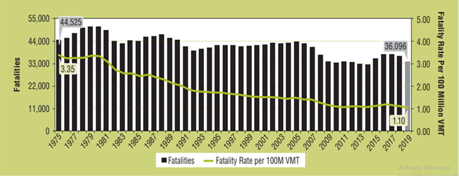
Fig. 1: US Road’s Fatality Rate per 100 million VMT, 1975-2019 [1].
Radar resolution is equal to , where C is the speed of light and BW is the system bandwidth. Continuous wave radars, as the name implies, continuously send radar signals toward targets, and thus provide continuous radar updates on the target. In CW radars the peak-to-average power is quite low (a few watts) and this factor makes such radars more economical for automotive applications compared to pulse-waveform radars [2].
There are many interesting applications or aspects of FMCW radars to be improved such as in [3], where authors mention improving the low resolution of FSK radars using LFM waveforms. In [3] and [4], the emphasis is on the design of a baseband signal processing system for FMCW radar where a three-ramp chirp is used to increase radar accuracy and shorten the measurement time without complicating the RF front-end. In [5] the authors have introduced a 60GHz LWA to do a simultaneous estimation of the direction of arrival (DOA) and ranging of objects providing 60 beam steering by sweeping from 50GHz to 60GHz. Human tracking is a vital research area. There is already a proposed microstrip LWA for tracking humans as shown in [6]. In [7] the authors have assessed different ways of walking such as slow or fast walking using the FMCW radar system. One of the most challenging issues of the multi-target FMCW radar systems is the existence of ghost targets. Any radar detection other than the main targets is considered a ghost target. It could have different causes and so the solutions are as diverse as the types of ghost targets themselves. For example, in [8] the ghost targets are caused by inter-radar interference and to suppress such ghost targets, authors use a carrier sensing method and interference replica to suppress the ghosts. In our proposed system there is an easy solution which will be discussed in section IV. The antenna used in any radar system is one of the main factors that determine the overall cost of the system. In this work, we have studied the application of a comb-line leaky-wave antenna for radar systems to explore the interesting characteristics of these antennas. In fact, leaky-wave antennas are modified waveguiding structures which might have modifications such as periodic slots or stubs. They allow electromagnetic waves to leak through them as they travel along the structure, giving leaky-wave antennas interesting properties [9]. The mechanism of wave leakage through each periodic slot is explained in [10]. The Floquet periodicity theorem [11] was applied to periodic leaky-wave antennas whereby the field of each slot could be expanded as a multiplication of a periodic function by the general exponential wave function of the form , in which is propagation constant and is attenuation factor. In a recent work [12], a periodic LWA has been used in a joint communication radar. In [13], a circularly polarized periodic LWA has been used for radar imaging.
II. FMCW WAVEFORMS
A typical FMCW radar system is shown in Fig. 2 which includes the following block diagrams of the transmitter, receiver, mixer, and analog to digital converter (A/D).
In simple words, an FMCW signal is generated at the transmitter side and sent via the transmitter antenna toward the receiver. At the receiver’s side, after receiving the echo signal reflected from a target, a mixer combines the chirp signal (reference signal) and the reflected signal. A low pass filter removes the higher frequency harmonics and keeps the intermediate frequency (IF) signal which then goes to the analog-to-digital converter and finally to the signal processing block for detection and range-Doppler mapping.
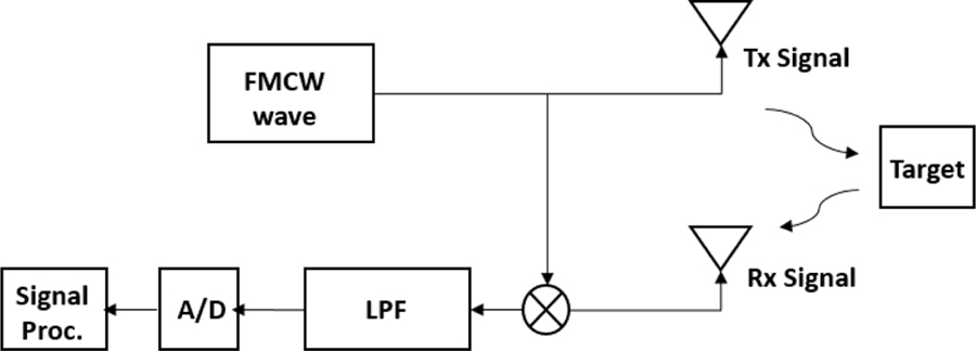
Fig. 2: Schematic of a generic FMCW Radar system.
A. FMCW signal model
The transmitted signal can be considered as equation(1):
| (1) |
in which, is the linear chirp function of the transmit frequency equal to while chirp could be exponential, quadratic, etc. but in this work, the linear chirp has been used. is the working frequency of radar, B is the bandwidth, is the signal amplitude and T is pulse duration. On the other hand, the receiving frequency is described in equation (2).
| (2) |
where is the time delay. A target moving with the velocity v gives the Doppler shift described by as
= v/c. The received signal is expressed by equation (3):
| (3) |
where is the amplitude of the received signal that is influenced by the radar cross section (RCS), the distance of the target, gains of transmitting and receiving antennas and the power used for the transmission. As Fig. 2 illustrates, once the FMCW signal is generated at the transmitter’s side, a branch of this signal is injected into the mixer that is at the receiver’s side. In this mixer, the reference signal and the received signal (echo from the target) are mixed or in other words, they are multiplied together, leading to higher-frequency components in addition to lower-frequency ones. To suppress the higher frequency components and get the IF signal (intermediate frequency signal), a low-pass filter is used right after the mixer. The IF signal is represented by . If a triangular waveform composed of two ramps (a positive and negative ramp) is used, then two beat frequencies and will emerge after the low pass filter (LPF) expressed by equations(4) and (5):
| (4) |
| (5) |
The reflected signal that returnsfrom a given target looks like the transmitted signal but in fact, it is the shifted version of the reference signal both in time and frequency. Figure 3 illustrates the sent and the received spectrograms (Tx and Rx chirps correspondingly). A chirp could also be in form of a sawtooth waveform as shown in Fig. 4. Based on this figure, we can write the following equations of the upbeat and downbeat frequencies:
| (6) |
| (7) |
Then solving for the equations (6) and (7) for R and , will result in equations (8) and (9):
| (8) |
| (9) |
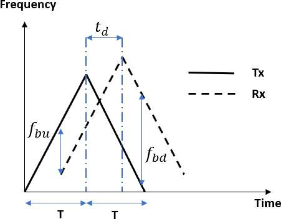
Fig. 3: Spectrogram of triangular chirp for transmittedand received signals.
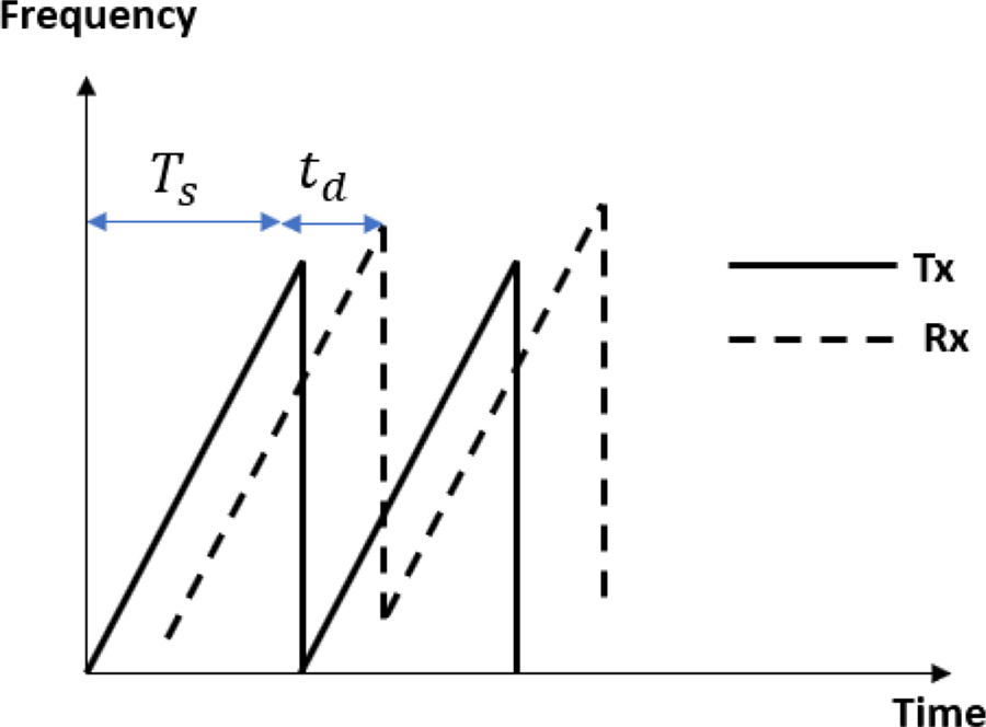
Fig. 4: Spectrogram of triangular chirp for transmittedand received signals.
III. THE PROPOSED RADAR STRUCTURE
The proposed 77 GHz automotive FMCW radar system is shown in Fig. 5. The design parameters of the RF components of this system, such as system bandwidth, antenna gain, noise figure, etc. are summarized in Table 1. The system design has been implemented using MATLAB Simulink. The main design parameters of the radar system are summarized in Table 1 which are chosen from [3].
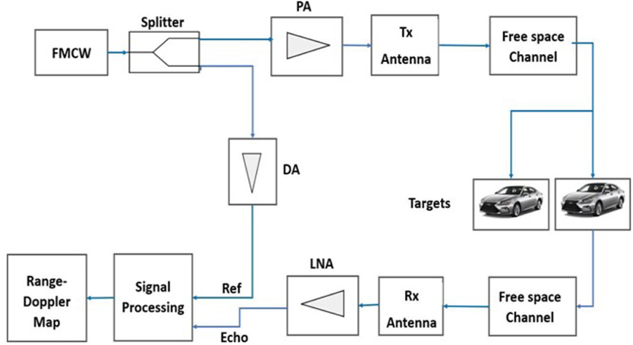
Fig. 5: The architecture of the multi-target FMCW automotive radar.
Table 1: Design parameters of the radar system
| Parameter | Explanation | Value |
|---|---|---|
| Fs | Sampling frequency | 150 MHz |
| BW | Bandwidth | 150 MHz |
| Tx Gain | Transmitter’s gain | 36 dB |
| Rx Gain | Receiver’s gain | 42 dB |
| NF | Noise figure | 4.5 |
A. FMCW signal block
This block generates FMCW signal of 77 GHz frequency which is a typical frequency for automotive applications. We could use any type of chirp including linear, quadratic, etc. The linear chirp itself could be up, down, or triangular. We have used both triangular and up-chirp in our proposed radar system.
B. Splitter
A splitter is a three-port and non-directional component that has the task of directing the input signal to two different outputs. A common type of splitter is the Wilkinson splitter.
C. Power amplifier
This component is used to boost a weak signal into a strong signal and denoise it.
D. Transmitter/receiver antenna
In this research, we propose the application of a leaky-wave antenna as a substitute for antenna array which is shown in Fig. 6 with the main dimensions summarized in Table 2. As we know, the automotive industry uses antenna array as a transmitting and receiving system. leaky-wave antennas have interesting properties that make them quite attractive for radar systems. By using the frequency scanning property of the leaky-wave antennas, we could control the antenna beam in different directions as described by [10]:
| (10) |
Once the frequency changes, the propagation constant changes and so does the direction of the main beam. The antenna proposed for this radar system is a comb-line leaky-wave antenna with the substrate Arlon AD 350 with permittivity =3.5. This comb-line leaky-wave antenna provides a simple beamforming structure and right/left-handed beam-scanning. The antenna structure is composed of 31 stubs to introduce periodicity and generate Floquet modes [4] and it is excited through two ports situated at both sides of theantenna.
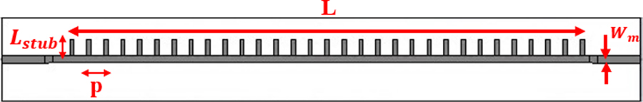
Fig. 6: Comb-line leaky-wave antenna as FMCW radar antenna.
The design parameters for our proposed comb-line leaky-wave antenna are summarized in Table 2. The wavelength corresponds to the radar frequency of 77 GHz. Microstrip width is set on 1mm which is in an appropriate range for width trace of antenna that works in 77 GHz. Antenna length is chosen to be approximately 20 to be long enough for the leakage factor to be small. Stub width and length are correspondingly 0.5 and 2mm that are chosen by running iterative simulations of CST software to achieve optimal values. The period is chosen to be smaller than wavelength to minimize grating lobes.
Table 2: Design parameters of comb-line leaky-wave antenna
| Parameter | Symbol | Value (mm) |
|---|---|---|
| Wavelength | 3.89 | |
| Microstrip width | 1 | |
| Antenna length | 75 | |
| Stub width | 0.5 | |
| Stub length | 2 | |
| Period | 2 | |
| Substrate thickness | 0.38 |
The following figure shows the propagation patterns of the comb-line leaky-wave antenna that proves the frequency scanning capability of it. By looking at the propagation patterns we can see that the comb-line leaky-wave antenna has both left and right-handed propagations and there are beams with decent gains at thesefrequencies.
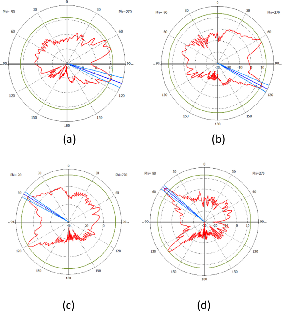
Fig. 7: Radiation patterns of the proposed comb-line leaky-wave antenna at = 0 showing right & left-handed beam scanning for frequencies a = 75 GHz, b = 77 GHz, c = 77.5 GHz and d = 79 GHz.
E. Propagation channel
The propagation channel is a free space medium that is modeled by applying time delay as well as attenuation of the transmitted FMCW signal because of the path loss expressed in the following equation:
| (11) |
where R is the propagation distance and the signal wavelength.
F. Target RCS
Every target could be attributed a radar cross section () value at a given frequency. This parameter specifies how much the backscatter power per steradian is echoed from the target. In our radar design we considered four road targets that are a truck, a car, a motorcycle, and a bike. Table 3 summarizes the RCS values considered for the targets at 77 GHz.
Table 3: Radar cross sections of targets in at f = 77 GHz
| Truck | Car | Motorcycle | Bike | |
| 50 | 25 | 15 |
G. Preamplifier
Preamplifier is a device for amplification and noise suppression of the echo signal. In the corresponding Simulink block, the attributed noise figure of this block is NF = 4.5 for the ambient temperature of T = 290K and the gain is 42.
H. Signal processing
The signal processing block is composed of four subblocks of a mixer, pulse buffer, range-Doppler response, and range-speed estimation. The mixer multiplies the reference signal with the echo signal which then generates IF signal. The pulse buffer block converts scalar samples to frame structure. The range-Doppler block receives the input IF signal and calculates the range-Doppler map using the FFT transform. The number of FFT points is 2048 in our platform. For range processing FFT windowing as well as Doppler processing FFT windowing we can use any of the 5 types of windows such as Hamming, Chebyshev, Hanning, Kaiser, and Taylor. Figure 8 summarizes the signal processing block and its subblocks.
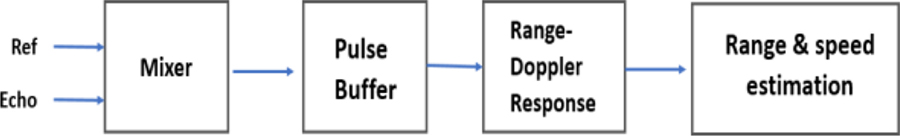
Fig. 8: Subblocks of the signal processing block.
IV. SIGNAL PROCESSING AND DETECTION
The proposed radar system was tested using 2 different FMCW chirps of sawtooth and triangular. The corresponding equations of both cases were discussed in section II (equations 4 - 9). In each case, the evaluation of the radar system was done using a range-Doppler map. In our simulations, we assume that the radar system is installed on a reference vehicle that is moving with a speed of 27.77 m/s and an initial range of 0 m. The range–Doppler map gives us the relative velocity of a vehicle in reference to the radar as well as the relative range as equations (12) and (13) express:
| (12) |
| (13) |
At the first stage, the triangular FMCW chirp was used in the radar system and the ghost target issue was challenging in this case. Since by increasing the number of actual targets, the number of ghost targets also increases. Based on our simulations, for example in the four-target scenario, we observed 12 ghost targets as shown in Fig. 9. For our proposed radar system when we use triangular chirp there is a linear equation that could be used to predict the number of ghost targets (G) which is G = 3 N, in which (N) is the number of targets. There are different methods for suppressing ghost targets as was briefly pointed out in the introduction section. But not every method works for every radar system. The authors think that in the triangular chirp the down-ramp causes some additional echoes and creates a scenario of “mirror ghosts”. If we closely observe Fig. 9, we notice that there are two groups of ghost targets, the ghost targets that appear right below the actual targets marked as Group I and the ghost targets that appear on the left- and right-hand side of the range-Doppler map marked as Group II. The ghost targets of Group I are exactly the mirror of actual targets with reference to the range axis (axis of symmetry) and thus the velocities of Group I’s ghost targets are the same, but the ranges are the opposite of the actual ones.
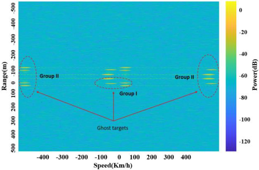
Fig. 9: Range-Doppler map for the 4-target scenario using triangular sweep.
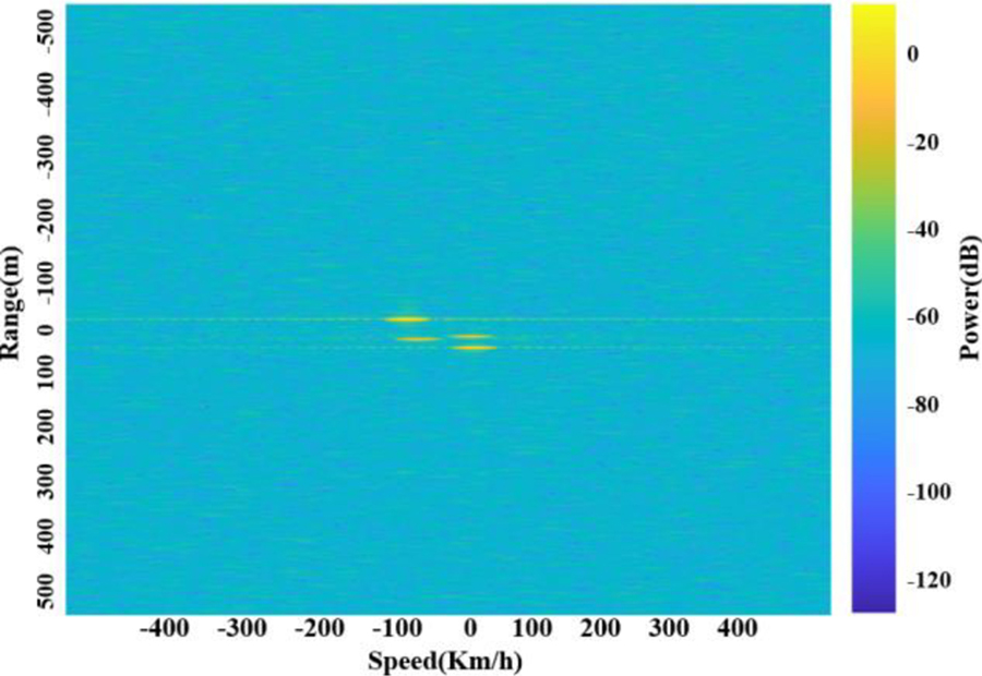
Fig. 10: Range-Doppler map using sawtooth sweep.
It is even more interesting to see the ghost targets of Group II. We can observe that some actual targets’ echoes project themselves onto the left- and right-hand side of the range-Doppler map. By looking at the ghost targets of Group II, we can see that they emerge on the two far ends of the map and mark very high velocities such as 400 Km/h which can’t be attributed to any vehicle, at least in the automotive perspective. Thus, they can be easily neglected. But the ghost targets of Group I could cause confusion in automotive scenarios since they are exactly within the same range of values or velocities as actual targets are. For our proposed system there is an easy fix and that is switching to the use of sawtooth chirp instead of the triangular chirp. Figure 10 illustrates that by switching to the sawtooth chirp the issue of the ghost targets is resolved.
As a figure of merit for the range-Doppler graphs in our radar system, we can compare the power of the echo signal with the power of the background noise using the right-hand side color bars in Figs. 9 and 10. We can observe that basically our target returns have power of about 20dB or higher which is an easily detectable value against the background noise which is about 80dB.
V. PERFORMANCE OF ANTENNA ARRAYS VERSUS SINGLE LWA
In this paper, several antenna arrays were designed, and their performances were evaluated compared to our proposed leaky-wave antenna. The small-signal S-parameters of each design was extracted as Touchstone file since as we know, we can get the S-parameters of any microwave device with n ports, as snp file where n shows the number of ports. CST Studio Microwave has the capability to extract the S-parameters in Touchstone format. For example, for our case, since we have only 2 feeding ports, the s2p file was extracted and directly plugged into the antenna blocks (transmitter and receiver) of the FMCW radar’s architecture in Simulink. In the following section we are going to introduce three antenna systems designed for our proposed FMCW radar system.
A. Inset feed microstrip patch array
This structure is composed of an array of 77 GHz antennas as illustrated on Fig. 11. The substrate used was Arlon AD 350 with permittivity value of r = 3.5.
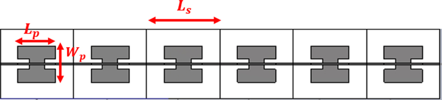
Fig. 11: Inset feed microstrip patch array.
Table 4: Design parameters of a single cell of patch array
| Parameter | Explanation | Value (mm) |
|---|---|---|
| Substrate length | 2.07 | |
| Substrate length | 2.07 | |
| Patch length | 1.08 | |
| Patch width | 1.10 | |
| Indentation length | 0.32 | |
| 0.12 |
B. Circular patch array with Buttler beamforming network
Buttler beamforming networks are very common structures for beam scanning. These networks are comprised of branch-line couplers, crossovers, and phase shifters. Figure 12 shows the different blocks of the Buttler matrix. Block A is a branch-line coupler which is a 90 hybrid coupler, and we have four of the same couplers on the structure. Block B is showing a microwave crossover which simply routes the signals. Block C is showing a 45 phase shifter and we have two phase shifters on the matrix. Block D is showing the circular patch antenna array designed for operation at 77GHz. The ports 1 to 4, on the left side of the Buttler matrix are the feed ports. At a given time, only one port is excited and three other ports are terminated using 50 terminators.
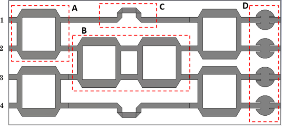
Fig. 12: Circular patch array with Buttler beamforming network.
Figure sets 13 to 15 summarize the beamforming behavior of Buttler beamforming network on the circular patch array as the structure is fed through any of the ports 1 to 4 on plane .
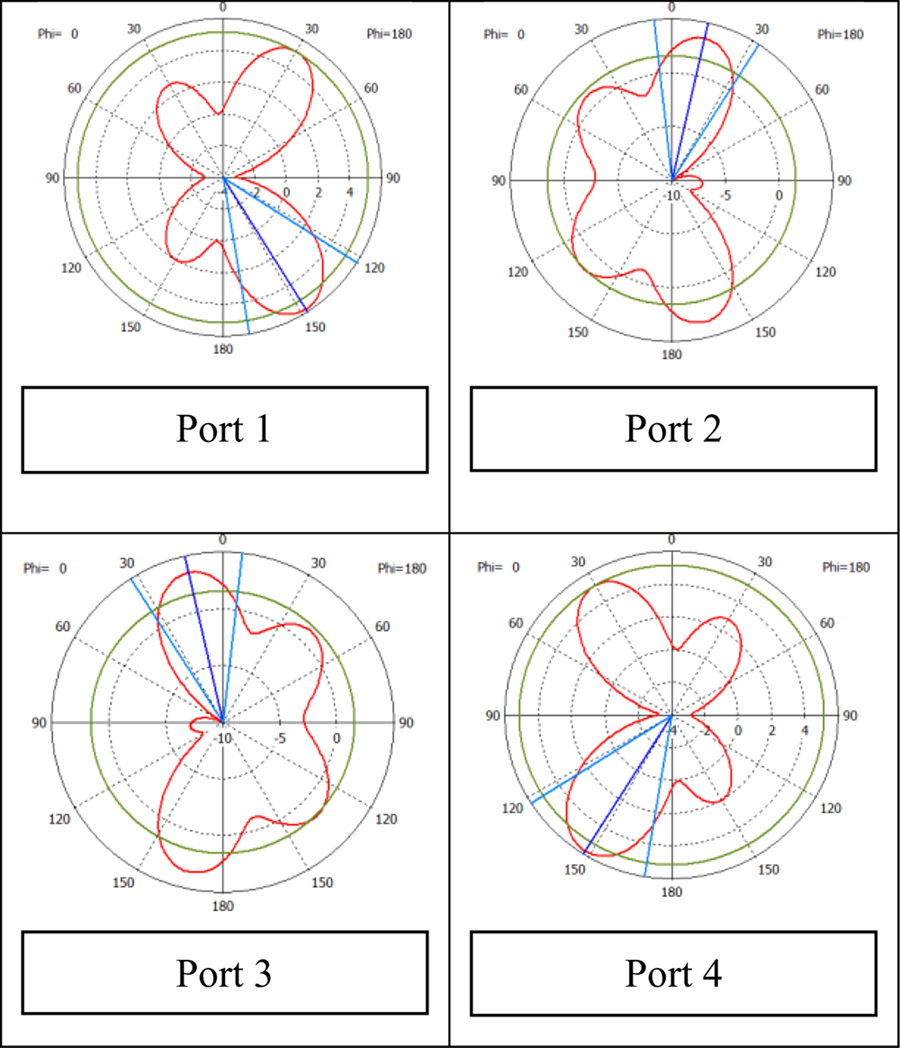
Fig. 13: Propagation patterns of the circular patch array with Buttler beamforming network at frequency of f =76.5 GHz.
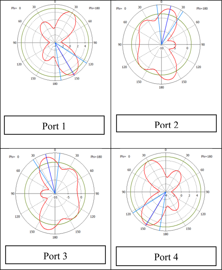
Fig. 14: Propagation patterns of the circular patch array with Buttler beamforming network at frequency of f =77 GHz.
By paying close look to the propagation patterns, we can observe the left-handed and right-handed beam patterns. The frequency range changes from 76.5 GHz to 77.5 GHz.
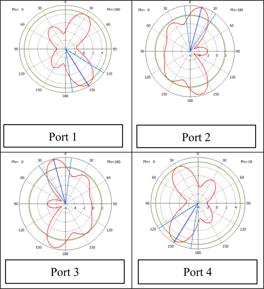
Fig. 15: Propagation patterns of the circular patch array with Buttler beamforming network at frequency of f =77.5 GHz.
At the central frequency of the angular directions of the main beam by switching between ports 1 to 4 are correspondingly , , and Tables 5, 6, and 7 summarize the range-Doppler data of the three antenna systems in the proposed FMCW radar system. The first four columns in each table correspondingly show the real velocity , real range (), real relative velocity of the target to the radar (), and the real relative range of the target to the radar () and these are fixed values in all three tables. The last two columns show the estimated relative velocity and the estimated relative range of each target. As was the case with the inset-fed patch antenna array, we believe by doing some antenna tuning and optimization in the designed array, we could possibly improve the gain. In this case, the radar returns have the power of 30dB to 35dB which are still detectable against the background noise with 80dB power.
Table 5: Range-Doppler results of circular patch array with Buttler Beamformer
| Target | Truck | Car | Motorcycle | Bike |
| (m/h) | 129.9 | 59.9 | 126 | 46.8 |
| (m) | 65 | 65 | 45 | 20 |
| (m/h) | +32.7 | 37.2 | 28.8 | 50.4 |
| (m) | 65 | 65 | 45 | 20 |
| (m/h) | +32.1 | 38.5 | +29.8 | 57.7 |
| (m) | 63.0 | 63 | 44.5 | 18.5 |
Table 6: Range-Doppler results of the Inset-fed patch array
| Target | Truck | Car | Motorcycle | Bike |
| (m/h) | 129.9 | 59.9 | 126 | 46.8 |
| (m) | 65 | 65 | 45 | 20 |
| (m/h) | +32.7 | 37.2 | 28.8 | 50.4 |
| (m) | 65 | 65 | 45 | 20 |
| (m/h) | +29.9 | 49.2 | +29.9 | 53.5 |
| (m) | 59.3 | 59.3 | 40.8 | 22.2 |
Table 7: Range-Doppler results of the Comb-line leaky-wave antenna
| Target | Truck | Car | Motorcycle | Bike |
| (m/h) | 129.9 | 59.9 | 126 | 46.8 |
| (m) | 65 | 65 | 45 | 20 |
| (m/h) | +32.7 | 37.2 | 28.8 | 50.4 |
| (m) | 65 | 65 | 45 | 20 |
| (m/h) | +32.1 | 40.6 | +27.8 | 55.6 |
| (m) | 63.0 | 63.0 | 44.5 | 20.7 |
In addition to the Tables 5, 6, and 7, the range-Doppler data of the three proposed antenna systems have been shown as graphs on Fig. 16. In this figure the horizontal axis is the speed of a target relative to the radar (V) and the vertical axis is the position of a target relative to the radar system (R). There are four curves in the figure. The blue curve is the reference curve, the red, green, and black curves show the range-Doppler responses of the circular patch array with Buttler beamforming network, the inset-fed patch array, and the comb-line leaky-wave antenna correspondingly. The pink circles show the range-Doppler margin of 3 targets. We can see that the Buttler beamformer’s performance is the best but at the cost of more complexity in design. The comb-line leaky-wave antenna has decent range-Doppler performance and is showing a better margin than the inset-fed patch array for target 2. Overall, the comb-line leaky-wave antenna shows a successful performance in range-Doppler detection of the proposed FMCW radar system.
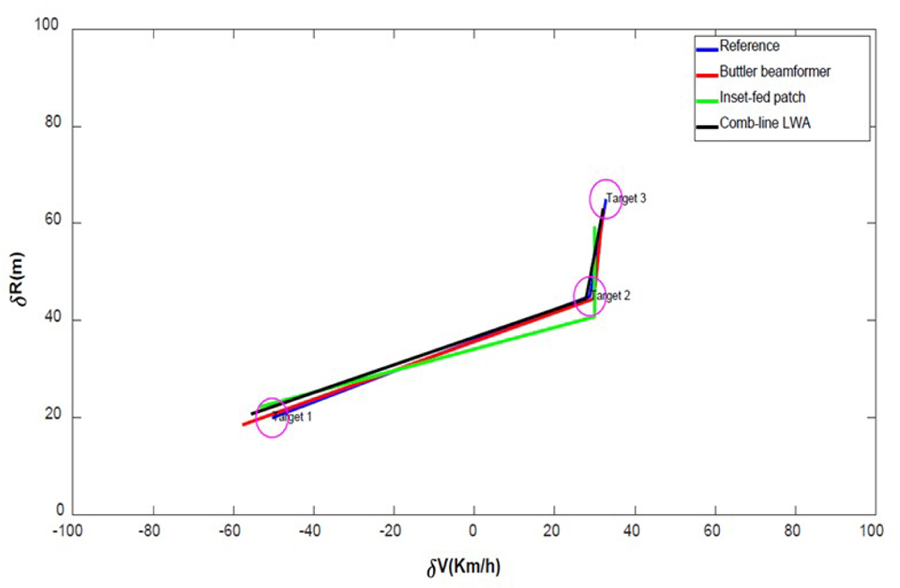
Fig. 16: Range-Doppler performance of the Buttler beamformer network, Inset-fed patch array and comb-line leaky-wave antenna.
VI. CONCLUSION
In this work, we proposed a comb-line leaky-wave antenna and compared the performance against the inset-fed patch antenna array and circular patch array controlled with a Buttler beamforming network. The main contribution of this work is introducing a novel frequency scanning system for the automotive industry by using a combline leaky-wave antenna. The proposed antenna is simple in structure and cheap to manufacture because most importantly unlike other antenna arrays, it does not need any phase shifters or, couplers or complex beamforming networks. Based on the results in section V, the authors believe that the functionality of the proposed leaky-wave antenna results in acceptable range and velocity margins for road safety and automotive applications. Observing the range-Doppler map in Fig. 9 shows that the ghost-target problem could be a critical issue in FMCW radars, especially if we use triangular chirp. The negative ramp of the triangular chirp creates images of the main targets in a symmetrical fashion and thus artificial and unreal echoes appear on the range-Doppler map. We discussed and categorized the ghost targets. Ghost targets of type II can be easily ignored because their range and velocity values are beyond real automotive scenarios. But ghost targets of type I, emerge exactly within the same velocity values of the genuine target returns and have the negated range values of real targets, which makes them significant to detect and suppress. The fix was using a sawtooth chirp to cancel out the effect of the negative ramp in the triangular chirp.
REFERENCES
[1] https://www.nhtsa.gov/
[2] M. Jankiraman, FMCW Radar Design, Artech House, 2018.
[3] C. Kärnfelt, A. Péden, A. Bazzi, G. El Haj Shhadé, M. Abbas, T. Chonavel, and F. Bodereau, “77 GHz ACC radar simulation platform,” 9th International Conference on Intelligent Transport Systems Telecommunications, (ITST), IEEE, 2009.
[4] J.-Jr Lin, Y.-P. Li, W. C. Hsu, and T. S. Li, “Design of an FMCW radar baseband signal processing system for automotive application,” SpringerPlus, vol. 5, no. 1, pp. 1-16, 2016.
[5] M. Steeg, A. Al Assad, and A. Stöhr, “Simultaneous DoA estimation and ranging of multiple objects using an FMCW radar with 60 GHz leaky-wave antennas,” 43rd International Conference on Infrared, Millimeter, and Terahertz Waves (IRMMW-THz), IEEE, 2018.
[6] S.-T. Yang and H. Ling, “Application of a microstrip leaky wave antenna for range–azimuth tracking of humans,” IEEE Geoscience and Remote Sensing Letters, vol. 10, no. 6, pp. 1384-1388, 2013.
[7] E. Gambi, G. Ciattaglia, A. De Santis, and L. Senigagliesi, “Millimeter wave radar data of people walking,” Data in Brief, vol. 31, pp. 105996, 2020.
[8] D. Ammen, M. Umehira, X. Wang, S. Takeda, and H. Kuroda, “A ghost target suppression technique using interference replica for automotive FMCW radars,” IEEE Radar Conference (RadarConf20), IEEE, 2020.
[9] F. B. Gross, Frontiers in Antennas: Next Generation Design & Engineering, McGraw-Hill Education, 2011.
[10] D. R. Jackson, C. Caloz, and T. Itoh, “Leaky-wave antennas,” Proceedings of the IEEE, vol. 100, no. 7, pp. 2194-2206, 2012.
[11] L. Brillouin, Wave Propagation in Periodic Structures, Dover Publications, 2003.
[12] M. Steeg, F. Exner, J. Tebart, A. Czylwik, A. Stöhr, “OFDM joint communication–radar with leakywave antennas,” Electronics Letters, vol. 56, no. 21, pp. 1139-1141, 2020.
[13] A. Zandamela, A. Al-Bassam, and D. Heberling, “Circularly polarized periodic leaky-wave antenna based on dielectric image line for millimeter-wave radar applications,” IEEE Antennas and Wireless Propagation Letters, vol. 20, no. 6, pp. 938-942, 2021.
BIOGRAPHIES

Masoud Sara has received his PhD in Electrical Engineering from the Michigan Tech university in 2021. His research interests are antenna design for biomedical hyperthermia, beamformers, and FMCW radar systems for road safety applications.

Warren F. Perger is a professor of Electrical and Computer Engineering department at Michigan Tech university and has been a faculty member since 1987.
ACES JOURNAL, Vol. 37, No. 9, 1005–1013.
doi: 10.13052/2022.ACES.J.370910
© 2022 River Publishers