A Novel Technique for Dynamic Analysis of an Electromagnetic Rail Launcher using FEM Coupled with Simplorer
J. Lydia, R. Karpagam, and R. Murugan
1Department of Electrical and Electronics Engineering, Easwari Engineering College, Chennai 600089, India
lydia.jeec@gmail.com, karpagamraj2013@gmail.com
2Department of Electrical and Electronics Engineering, St. Peter’s College of Engineering and Technology, Chennai 600054, India
ramumurugan_r@rediffmail.com
Submitted On: June 27, 2021; Accepted On: February 8, 2022
Abstract
The performance of a rail gun depends on the current density distribution over the rail and armature as it determines the force that accelerates the projectile of the rail gun. A finite element method (FEM) coupled with Simplorer was developed to model and study the performance of the rail gun. The rail gun was modeled using an ANSYS eddy current field solver to determine the current density distribution and equivalent rail gun circuit for the given rail gun geometry. The armature velocity was then calculated using Simplorer by coupling the obtained equivalent rail gun circuit and exciting the rails using a capacitor-based pulsed power supply (PPS) system. The FEM coupled with Simplorer method was verified by numerical calculations for the rectangular rails and also with other researchers’ value, and that showed a good agreement between the results. Further, the current density distribution over rails and armature and velocity of the armature was calculated for different rail cross sections such as circular concave, circular convex, rectangular concave, rectangular convex, T-shaped concave, and T-shaped convex with a C-shaped armature. It was observed that the circular convex rail gun with C-shaped armature showed minimum current density distribution and gives a higher value of armature velocity compared with other rail gun structures. Thus, the circular convex armature was found to be suitable for the electromagnetic (EM) rail gun launchingsystem.
Keywords: ANSYS coupled with Simplorer (ACS), current density, inductance gradient of rails, pulsed power supply system.
I. INTRODUCTION
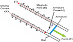
A rail gun is a type of electromagnetic (EM) launch system that has great potential in EM applications and is widely studied [1, 2]. It has become a research hotspot in the field of military equipment with the advantages of having a simple structure, fast response, and accurate control. In the future, this technology may be used to launch small satellites into a low earth orbit or even into space at low cost [3, 4]. The simple rail gun has mainly three parts: two parallel rails, an armature, and a pulsed power supply (PPS) system. When pulse current flows along one rail, it crosses the armature, returns back along the second rail, and tends to accelerate the armature. Its work is based on a very basic EM concept known as the Lorentz force law, which can be shown by where F is the force acting on the armature, I is the current passing through the armature, and is the inductance gradient of the rails [5]. The representation of a rail gun is shown in Figure 1.
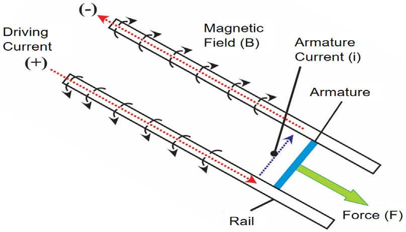
Figure 1: A simple rail gun representation [6].
The current density distribution in the rails and armature and inductance gradient of the rails plays an important role in a rail gun design as they determine the force that accelerates the armature with higher velocity. It also depends on the rail and armature shape, its cross sections, magnitude, and shape of the current pulse supplied to the rails. For the last several years, research has been carried out to calculate the same using 2D analysis by varying rail shapes and its dimensions by neglecting the armature effect [5–9]. Researchers also used 3D analysis using analytical methods such as finite element method (FEM) and finite difference method (FDM) by considering the armature effect, and the armature was assumed to be stationary [10–12]. These results were acceptable for lower values of armature velocity and were inconsistent for higher values of armature velocity [13]. Nowadays, researchers are focusing to develop field circuit coupling methods to study the performance of a rail gun under dynamic conditions of the armature [14, 15]. The EM coupled analysis using LS-Dyna was proposed to obtain a higher muzzle velocity, improved current density distribution, and inductance gradient of the tapered rails [16]. A hybrid robust optimization method was proposed to improve the energy efficiency of the rail gun using the polynomial chaos expansion method coupled with Latin hypercube design to study the influence of muzzle velocity, projectile diameter, projectile length, launch angle, and guidance coefficient [17]. The velocity and force acting on the armature were optimized by solving differential equations using the fourth-order Runge-Kutta method, and particle swarm optimization (PSO) algorithm was used to optimize the rail gun parameters [18]. The 3D transient finite element solver was adopted to solve the field circuit coupled problem and calculate the armature velocity of the rail gun [19, 20].
In this article, by using Maxwell’s ANSYS software, which has an inbuilt electric field simulator named Simplorer, a method was developed to study the performance of the rail gun for various rails and armature shapes under dynamic conditions of the armature. The current density distribution in the rails and armature and the equivalent electric circuit of rail gun were obtained using the ANSYS eddy current field solver by sweeping the armature position. The armature velocity was calculated using Simplorer coupled with the ANSYS eddy current field solver by exciting the rail gun with the capacitor-based PPS system. The method was validated by numerical method by simulating the rectangular rail cross section and simulating the rail gun structure that was used by other researchers. The results obtained by ANSYS coupled with Simplorer (ACS) method showed good agreement between the results. Then, the work was extended to study the performance of the rail gun for various rail gun structures by calculating the current density distribution over the rails and armature and the velocity of the armature.
II. GOVERNING EQUATIONS
The inductance gradient , magnetic flux density between the rails, the current density distribution, and the force acting on the rails are obtained using the eddy current solver [20].
In the analysis, the magnetic vector potential (A) is obtained as follows:
| (1) |
where is the magnetic vector potential, is the electric scalar potential, is the magnetic permeability, is the angular frequency, is the relative permittivity, and is the conductivity of the conductor.
The eddy current solver solves the magnetic vector potential to obtain the magnetic flux density as follows:
| (2) |
The magnetic field intensity and the current density distribution are calculated using the following relationships:
| (3) |
| (4) |
Then the energy stored in the system is given as
| (5) |
The instantaneous energy of system is equal to
| (6) |
where is the instantaneous value of current.
Using the above equations, the ANSYS Maxwell’s solver calculates the inductance gradient of the rails which is given as
| (7) |
Because the inductance value of the EM launcher is proportional to the position of the armature, the inductance of the rails are varied with respect to armature position, as given in the following:
| (8) |
where is the initial position of the armature and is the displacement of the armature.
III. DESIGN CALCULATION OF PULSED POWER SUPPLY SYSTEM
The PPS system has an important function in the EM launcher system because it discharges a huge amount of electrical energy to the rails within a short duration. The PPS system, which is generally a capacitor-based system, gets energy from a high-voltage transformer and a rectifier circuit, which have advantages of mature development, simple control, operational reliability, and lower cost [21, 22]. The capacitor-based PPS system was made up of units called pulse forming units and they were assembled into many sections called modules. These modules were concurrently switched to get the desired velocity of the projectile by using thyristors [23, 24]. The design of PPS system depends on the muzzle velocity of the armature. To get the desired velocity of the armature, the PPS system stores enough energy to deliver the current required to accelerate the armature. The driving current for obtaining the desired velocity of the armature, time period up to which the armature has contact with rails to get the desired velocity of the armature, and the amount of energy stored by the capacitor-based PPS were calculated using the numerical formula given below.
The muzzle velocity of the rail gun is given by the empirical formula [25]
| (9) |
where is the inductance gradient of the rails (H/m), D is the length of the rails (m), I is the driving current (A), and m is the mass of projectile (kg).
The driving current supplied to the rails was obtained by assuming the muzzle velocity of the armature. The time period up to which the projectile has contact with the rails to get the desired velocity of the projectile was obtained by substituting the driving current supplied to rails in eqn (2)
| (10) |
where t is the time period of the armature in the rails (s), m is the mass of the armature (kg), D is the length of the rails (m), is the inductance gradient of rails (H/m), and I is the driving current (A).
The PPS system stores enough amount of energy and supplies the driving current to rails until the armature exits from the rails. The energy stored by the capacitor was calculated by assuming 10% efficiency, and it is given as follows:
Energy stored by the capacitor = (Energy stored in the rails at muzzle end)/(Efficiency of the rail gun).
The amount of energy stored in the rails at the muzzle end when the armature exits from the rails wascalculated by
| (11) |
where E is the energy stored at the muzzle end (Joules), m is the mass of the armature (kg), and v is the velocity of the armature (m/s).
The required voltage to energize the PPS capacitor was calculated by
| (12) |
where C is the capacitance of the capacitor (F) and v is the required voltage to charge the capacitor.
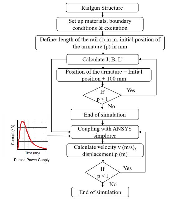
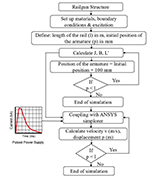
Figure 2: Process of ACS method.

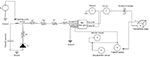
Figure 3: Electrical equivalent circuit model of rail gun.
IV. PROCESS OF DYNAMIC ANALYSIS OF RAIL GUN USING THE ACS METHOD
Figure 2 shows the process of ACS method which was used to study the performance of the rail gun. Initially, the properties of the materials, boundary conditions, and excitation of rails were assigned for a given rail gun structure by creating meshes. The meshing was done over the length based on selecting the geometric region for a maximum of 1000 elements for armature and 2000 elements for rails. Then, the parametric sweep analysis was carried out to determine the current density distribution and magnetic density distribution over rails and armature and the inductance of the rails. Initially, in the parametric sweep analysis, the rail length and initial position of armature were assigned and current density (J), magnetic field distribution (B), and the inductance gradient were calculated. Then, the armature position was incremented and, once again, J, B, and were calculated and the process was repeated until the armature reached the defined rail length. Then the equivalent rail gun circuit, which was obtained at the end of FEM analysis, was coupled with Simplorer and the armature velocity and displacement of the armature were calculated by exciting the rails with PPS system. In Simplorer, the rail gun circuit was excited with the PPS system and the position of armature and velocity of the armature were calculated. The solver checks the armature position, and when the armature position was less than the defined rail length, the position of the armature was once again given as input to the rail gun circuit and the velocity and position of the armature were calculated, and the process was repeated until the armature reached the defined rail length.
Figure 3 shows the electrical equivalent circuit model of the rail gun system coupled with ANSYS Simplorer. The capacitor is connected to the rails through cable (L2, R2) and the pulse shaping inductance (L1, R1) is used to generate the desired shape of current pulse. The capacitor is charged to rated voltage through high-voltage DC supply and it is connected to rails once it is charged to its rated value by closing the triggering pulse switch. The current delivered by the capacitor and the position of armature are given as inputs to the rail gun circuit (EM rail gun). The rail gun circuit calculates the force acting on the armature which is considered as a translational mass based on the current delivered by the capacitor and inductance gradient of the rails. The force is thus generated as a result of high discharge current that propels the armature mass (translational mass) with a frictional damper. The change in position of the armature motion is recorded using a position sensor. Then the velocity of the armature and the distance traveled by the armature is recorded using velocity and displacementsensor.
V. METHODS AND MATERIALS
To validate the concept of the ACS method for rail gun design, a rectangular rail cross section was used to accelerate the armature with a muzzle velocity of 1500 m/s. In this rail gun model, the length of rail was 1 m, the cross section area was 1500 mm, and the separation between rails was 20 cm. The armature length was 20 cm and mass of the armature was 100 g. The rails and armature were made up of a solid copper and aluminum conductor, and the properties of the materials used for simulation are given in Table 1.
To accelerate the armature with the desired velocity, the PPS system delivers the current until the armature exits from the rails. The PPS design parameters were calculated using the numerical formula as discussed in Section II and are given in Table 2.
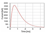
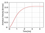
The current density distribution over the rails and armature and velocity of the armature depends on the contact pressure and friction between the rails and armature and the shape of current waveform. The effect of friction coefficient is not predominant at high velocity of the armature, and, therefore, its value is maintained as constant. Hence, in this work, it was assumed to be 0.1 [26]. Initially, the armature was kept at 0.1 m at the breech end and a current of 216 kA in the high frequency limit was applied to rails, and the current density distribution and velocity of the armature were obtained by sweeping the armature position with an increment of 100 mm using the ACS method as shown in Figures 4 and 5.
From the figures, it is observed that the current delivered by the PPS system is 216 kA and the velocity of the armature is 1500 m/s at 1.31 ms, which shows a good agreement with numerical calculations.
Table 1: Rail and armature material properties
| Rails | Copper | 5.8 10 | 8940 |
| Armature | Aluminum | 3.5 10 | 2800 |
Table 2: Pulsed power supply system parameters
| 216 | ||
|---|---|---|
| 1.3 | ||
| 112.5 | ||
| 1.125 (for 10% of rail gun efficiency) | ||
| 3.75 (total capacitance of 160 mF) | ||
| 5 H, 1 mH |
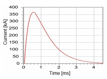
Figure 4: Pulsed power capacitive discharge current.
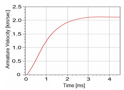
Figure 5: Velocity of the armature.
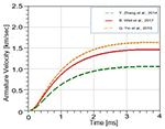
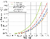
To validate the ACS method further, the rail gun model of other researchers was simulated and the velocity of the armature was calculated, as shown in Figure 6. The simulated results were compared with values of other researchers and are given in Table 3.
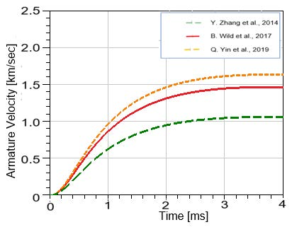
Figure 6: Armature velocity of the other researchers.
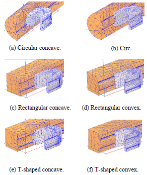
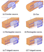
Figure 7: Different rail gun geometries.
From Table 3, it is observed that the values obtained using the ACS method show a good agreement with the values of other researchers.
Table 3: Comparison of other researchers’ results
| Zhang et al. (2014) [14] | Field circuit method | 1.01 (2.5 ms) | 1.01 (2.5 ms) |
| Wild et al. (2017) | Finite element method | 1.45 (2.5 ms) | 1.43 (2.5 ms) |
| Yin et al. (2019) | Finite element method | 1.5 (2.6 ms) | 1.55 (2.6 ms) |
Hence, in this work, the ACS method was used and simulated further to study the effect of rails and armature shape over current density distribution in rails and armature.
VI. RESULTS AND DISCUSSIONS
To study the effect of rails and armature shape over the current density distribution, different rail gun structures such as rectangular concave and convex, circular concave and convex, T-shaped concave, and convex rails with C-shaped armature, which are shown in Figure 7, were considered and simulated.
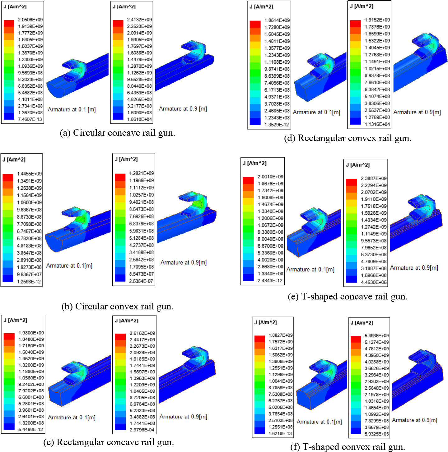
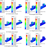
Figure 8: (a)–(f). Current density distribution for different rail gun structures at 0.1 m and 0.9 m position.
Figure 8 shows the current density distribution in the rails and armature for different rail gun structures obtained from the simulation at positions 0.1 and 0.9 m. From Figure 8, it is observed that current density distribution in the rails and armature is non-uniform when sliding along the rails. Moreover, the current distribution is higher over the corners and on the surface of the rails and armature edges. It is observed that the current does not penetrate deeper into the rails and armature when the armature is at the breech end, but it penetrates deeper into the rails and armature when the armature is at the muzzle end. This is mainly due to the velocity skin effect between the rails and armature. It is also observed that among the various rails and armature shapes, the circular convex rail gun shows minimum current density concentration in the armature of about 1.4455 10 A/m at the breech end and 1.2821 10 A/m at the muzzle end. Thus, the circular convex rails possess minimum current density concentration in the armature compared to the other rail gun structures. As the current hotspot is less, this armature model suits the launching process and the armature does not get destroyed before leaving the muzzle end of the rails. The ANSYS calculates the equivalent value of the rail gun inductance with respect to armature positions by using the current density distribution and magnetic field distribution over rails and armature.
The expressions of resultant inductance (H/m) of rails are given in eqn (13)–(18) for various configurations.
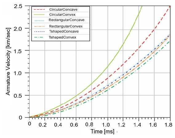
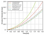
Figure 9: Velocity of the armature for different rail gun structures.
Circular convex rail gun:
| (13) |
Circular convex rail gun:
| (14) |
Rectangular concave rail gun:
| (15) |
Rectangular convex rail gun:
| (16) |
T-shaped concave rail gun:
| (17) |
T-shaped convex rail gun:
| (18) |
where is the armature position.
The rail gun equivalent circuit was then coupled with Simplorer and excited by the capacitor-based PPS system, and the velocity and distance traveled by the armature were calculated and are shown in Figures 9 and 10.
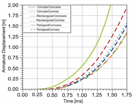
Figure 10: Displacement of the armature for different rail gun structures.
The values of velocity and displacement of the armature for different rail structures are given in Table 4.
Table 4: Velocity and displacement of the projectile for different rail gun structures
| Circular concave | 1.3140 | 0.8065 |
| Circular convex | 1.9990 | 1.3524 |
| Rectangular concave | 1.1852 | 0.6924 |
| Rectangular convex | 1.0528 | 0.5703 |
| T-shaped concave | 1.1769 | 0.6377 |
| T-shaped convex | 1.0347 | 0.5604 |
From Table 4, it is observed that the circular convex rail gun with C-shaped armature achieves velocity of about 1.99 km/s at 1.3 ms with armature displacement of 1.35 m compared with other rail gun structures. Hence, circular convex rails with C-shaped armature may be considered while designing the rail gun system.
VII. CONCLUSION
In this study, the ACS method was developed to study the performance of the rail gun. The method was validated for rectangular rail cross section with numerical calculations and further validated against various rail gun structures that were used by other researchers. The obtained results showed good agreement between the results. Then the current density distribution over rails and armature and velocity of the armature were calculated for different rail gun structures such as circular concave, circular convex, rectangular concave, rectangular convex, T-shaped concave, and T-shaped convex with a C-shaped armature for various rail gun structures. It was observed that the circular convex with C-shaped armature showed a lower current density distribution over rails and armature and gave a higher value of armature velocity compared with other rail gun structures. Thus, it can be concluded that the circular convex armature is suitable for the EM rail gun launching system.
ACKNOWLEDGMENT
The authors would like to thank all the reviewers and the editor for their valuable comments to enhance this manuscript. The authors wish to thank the Department of Science & Technology, Government of India, for funding the Research Infrastructure under the Scheme entitled “Funds for the Improvement of S&T Infrastructure (DST-FIST)” Ref. No. SR/FST/College – 110/2017.
REFERENCES
[1] S. Hundertmark, G. Vincent, D. Simicic, and M. Schneider, “Increasing Launch Efficiency with the PEGASUS Launcher,” IEEE Transactions on Plasma Science, vol. 45, no. 7, pp. 1607-1613, Jul. 2017.
[2] I. R. McNab, “Developments in Pulsed Power Technology,” IEEE Transactions on Magnetics, vol. 37, no. 1, pp. 375–378, Jan. 2001.
[3] H. D. Fair, “Guest Editorial the Past, Present, and Future of Electromagnetic Launch Technology and the IEEE International EML Symposia,” IEEE Transactions on Plasma Science, vol. 41, no. 5, pp. 1024–1027, May 2013.
[4] C. Gong, X. Yu, and X. Liu, “Study on the System Efficiency of the Capacitive Pulsed-power Supply,” IEEE Transactions on Plasma Science, vol. 43, no. 5, pp. 1441–1447, May 2015.
[5] M. N. S. Kumar, R. Murugan, “Analysis of Inductance Gradient and Current Density Distribution over Different Cross-section of Rails,” International Journal of Electrical and Computer Engineering, vol. 8, no. 02, pp. 723-729,Apr. 2018.
[6] M. N. S. Kumar, R. Murugan, and P. Shivkumar, “Inductance Gradient and Current Density Distribution for T-shaped Convex and Concave Rail Cross-sections,” International Journal of Engineering & Technology (UAE), vol. 7, no. 01, pp. 237-240, Mar. 2018.
[7] M. S. Bayati and A. Keshtkar, “Study of the Current Distribution, Magnetic Field, and Inductance Gradient of Rectangular and Circular Rail Guns,” IEEE Transactions on Plasma Science, vol. 41, no. 5, pp. 1376-1381, May 2013.
[8] A. Keshtkar, S. Bayati, and A. Keshtkar, “Derivation of a Formula for Inductance Gradient using Intelligent Estimation Method,” IEEE 2008 14th Symposium on Electromagnetic Launch Technology, pp. 1-4, Jun. 2008.
[9] M. S. Bayati and A. Keshtkar “Novel Study of the Rail’s Geometry in the Electromagnetic Launcher,” IEEE Transactions on Plasma Science, vol. 43, no. 5, pp. 1652-1656, May 2015.
[10] M. S. Bayati and K. Amiri, “Study of Various C-Shaped Armatures in Electromagnetic Launcher,” Applied Computational Electromagnetics Society Journal, vol. 30, no. 9, pp. 1029-1034,Sep. 2015.
[11] D. Ceylan, M. Karagoz, Y. Cevik, B. Yildirim, H. Polat, and O. Keysan, “Simulations and Experiments of EMFY-1 Electromagnetic Launcher,” IEEE Transactions on Plasma Science, vol. 47, no.7, pp. 3336-3343, Jul. 2019.
[12] J. Dong, J. Zhang, J. Li, Y. Gui, Y. Cui, S. Li, and N. Su, “The 100-kJ Modular Pulsed Power Units for Railgun,” IEEE Transactions on Plasma Science, vol. 39, no. 1, pp. 275-278, Jan. 2011.
[13] W. Li, Y. Hu, J. Feng, Y. Zhang, and D. Jing, “Research on Armature Structure Optimization of Rail Gun Based on Multiple Linear Regression,” IEEE Transactions on Plasma Science, vol. 47, no. 11, pp. 5042-5048, Nov. 2019.
[14] Y. Zhang, W. Qin, J. Liao, and J. Ruan, “Optimization Design of Multiparameters in Rail Launcher System,” Sensors & Transducers, vol. 171, issue 5, pp. 115–120, May 2014.
[15] Y. Hu, P. Ma, M. Yang, and Z. Wang, “Validation and Optimization of Modular Railgun Model,” IEEE 2012 16 International Symposium on Electromagnetic Launch Technology (EML), pp. 1–6, May 2012.
[16] S. R. Praneeth, D. Chaudhuri, B. Singh, S. Chatterjee, and G. Bhuvaneswari, “Analysis of an Electromagnetic Railgun with Tapered Rails and Concave Armature Using 3-D FEM,” IEEE 2019 12th International Symposium on Linear Drives for Industry Applications (LDIA), pp. 1-4, Jul. 2019.
[17] X. Shang, T. Chao, P. Ma, and M. Yang, “Simulation and Robust Optimization Design for Electromagnetic Railgun Performance,” IEEE Transactions on Plasma Science, vol. 47, no. 6, pp. 2964-2970, Jun. 2019.
[18] A. Shiri and M. Allahyari, “Sensitivity Analysis and Optimization of Railguns Using Circuit Model,” IEEE Transactions on Plasma Science, vol. 47, no. 11, pp. 5139-5147, Nov. 2019.
[19] C. Li, L. Chen, Z. Wang, J. Ruan, P. Wu, J. He, and S. Xia, “Influence of Armature Movement Velocity on the Magnetic Field Distribution and Current Density Distribution in Railgun,” IEEE Transactions on Plasma Science, vol. 48, issue 6, pp. 2308-2315, Jun. 2020.
[20] Q. Lin, B. Li, “Field-circuit Coupled Analysis of a Series-augmented Electromagnetic Railgun,” IEEE Transactions on Plasma Science, vol. 48, issue 6, pp. 2287-2293, Jun. 2020.
[21] B. E. Fridman, R. Sh. Enikeev, N. A. Kovrizhnykh, K. M. Lobanov, and R. A. Serebrov, “A 0.5 MJ 18 KV Module of Capacitive Energy Storage,” 2019 IEEE Pulsed Power Conference, vol. 39, no. 2, pp. 61-65, Jul. 2009.
[22] L. Dai, Y. Wang, Q. Zhang, W. Li, W. Lu, H. Dong, Q. Huang, and F. Lin, “Effect of Sequence Discharge on Components in a 600-kJ PPS Used for Electromagnetic Launch System,” IEEE 2012 16th International Symposium on Electromagnetic Launch Technology (EML), pp. 1-6, May 2012.
[23] X. Liu, X. Yu, and X. Liu, “Performance Analysis and Parameter Optimization of CPPS-based Electromagnetic Railgun System,” IEEE Transactions on Plasma Science, vol. 44, no. 3, pp. 281-288, Mar. 2016.
[24] T. M. Abdo, A. L. Elrefai, A. A. Adly, and O. A. Mahgoub, “Performance Analysis of Coil-gun Electromagnetic Launcher Using a Finite Element Coupled Model,” 2016 Eighteenth International Middle East Power Systems Conference (MEPCON), pp. 506-511, Dec. 2016.
[25] E. Cholaki, S. Ahmadvand, E. Mahmodi, and M. H. Sahafi, “Design and Calculation of Railgun Velocity and Study on Frictional Effects,” 3rd International Conference of Science & Engineering in Technology Era, pp. 1-6, Aug. 2017.
[26] J. Gallant, P. Lehmann, “Experiments with Brush Projectiles in a Parallel Augmented Railgun,” IEEE Transactions on Magnetics, vol. 41, issue 1, pp. 188-193, Jan. 2005.
BIOGRAPHIES

J. Lydia is currently a Research Scholar, pursuing her Ph.D. degree under the Faculty of Electrical Engineering, Anna University, Chennai, India. She received the B.E. degree in Electrical and Electronics Engineering from Easwari Engineering College, Chennai, India. She received the M.E. degree in Power Electronics and Drives from the Karunya Institute of Technology and Sciences, Deemed University, in 2006.
She is currently an Assistant Professor with the Department of Electrical and Electronics Engineering, Easwari Engineering College and works in the fields of Electromagnetic Fields and High-Voltage Engineering. She is a member of ACES and MISTE.

R. Karpagam received the Ph.D. degree from the Indian Institute of Technology, Chennai, India, in 2013.
She is currently an Associate Professor with the Department of Electrical and Electronics Engineering, Easwari Engineering College, Chennai, India. Her research interests include Partial Discharge Studies, Space Charge Measurements in Epoxy Nanocomposites, and Power Electronics. She is a member of ACES and IET.

R. Murugan received the bachelor’s degree in Electrical and Electronics Engineering from the University of Madras, Chennai, India, in April 1996. He received the master’s degree in High-Voltage Engineering from the College of Engineering, Anna University, Guindy, Chennai, India, in February 1999 and the Ph.D. degree from the Electrical and Electronics Engineering Department, Anna University in 2011.
His main areas of research interest are Electromagnetic Field and High-Voltage Engineering.
ACES JOURNAL, Vol. 37, No. 2, 229–237.
doi: 10.13052/2022.ACES.J.370212
© 2021 River Publishers