Reduced Modeling for Electromagnetic Coupling to Randomly Wiring Automotive Cable Harness
Pei Xiao, Jiawei Li, Chao Zhang, Jinxin Li, and Gaosheng Li
1College of Electrical and Information Engineering, Hunan University, Changsha 410012, China
gaosheng7070@vip.163.com
*Corresponding author: Gaosheng Li
2College of Computer Science and Electronic Engineering, Hunan University, Changsha 410082, China
3State Key Laboratory of Millimeter Waves, Southeast University Nanjing, Jiangsu 210096, China
jxli@hnu.edu.cn
Submitted On: August 20, 2021; Accepted On: December 28, 2021
Abstract
The random wiring of automotive cable harness makes electromagnetic compatibility (EMC) analysis of the whole vehicle very complicated; thus, this paper proposes a simplification modeling technique to model the electromagnetic (EM) illumination on automotive cable harness. First, the stochastic process theory is applied to determine the cable route in a randomly bundling way. Then, the inductance and capacitance parameters of the cable harness at different location are established according to multiconductor transmission lines network (MTLN) theory. On this basis, the simplification modeling technique is developed to generate the electrical and geometrical parameters of the equivalent cable model. Finally, a model of shielded nine-conductor with randomly twisted and a model of unshielded nine-conductor with stochastic wiring in the vehicle are performed to validate the proposed approach by full-wave simulation. The presented method simplifies the complexity of modeling the complete cable harness significantly with a good accuracy.
Keywords: Random wiring, automotive cable harness, simplification modeling, EM coupling, stochastic process.
I. INTRODUCTION
The cable harness provides a main gateway for electromagnetic interference (EMI) in automotive system. The unreasonable electromagnetic compatibility (EMC) design of cable harness will produce EMI to other on-board electronic equipment, bringing great safety risks to the system [1–4]. Theoretical research and engineering practice indicate that many electromechanical systems cannot satisfy EMC standards, which can be attributed to the EMI generated by cables [5–8]. As for the electromagnetic (EM) coupling analysis in modern automotive industry, reliable and efficient generation of a full numerical model of automotive cable harness is increasingly welcomed by the EMC designers [9-12]. Therefore, a more effective method to solve the modeling problem of automotive cable harness is needed.
During the wiring process in automotive, the cable harness always has some stochastic wiring factors of “spatial bending” and “randomness” as shown inFigure 1 [13–15], which bring a great challenge to the modeling of the EM illumination. Conventional modeling and simulation methods cannot easily accommodate complicated automotive system because of the difficulties in EMC modeling for cable harness [16–18]. Numerical simulation of the whole cable harness model requires strict conditions on calculation resource and even makes it impossible. Therefore, having the purpose of simplifying the structural modeling and improving the analytic efficiency, this paper focuses on the simplification technique of automotive cable harness with stochastic wiring factors.

Figure 1: Schematic diagram of automobile wiring harness distribution.
The equivalent cable bundle method (ECBM) is a modeling method that reduces multiconductor to no more than four conductors. The ECBM method is first presented to simplify the modeling of the EM illumination on multiconductor above the ideal conducting plane, which is used to predict the coupling common-mode (CM) current [19]. On this basis, the ECBM method is extended to model the EM radiated emission from multiconductor above an ideal conducting plane [20]. Besides, the ECBM method is applied to solve the crosstalk calculation problem of cable harness with the situation in an ideal conductive plane, an ideal cylindrical shielded cavity, and an orthogonal plane [21]. Moreover, some literatures have used the ECBM method to obtain induced current on differentialcables [22].
The existing ECBM method mainly aims at simplifying the deterministic wiring cable harness; however, uncertain factors for the application cannot be ignored. The generation of cross-sectional geometry for randomly wiring cable harness is quite different from that in a deterministic wiring way reflected in the processing of random wiring parameters.
Therefore, this paper proposes a generalized ECBM method for the EM illumination on cable harness with stochastic wiring factors. First, the stochastic process theory is applied to determine the cable route in a randomly bundling way. Second, the inductance and capacitance parameters of the cable harness at different locations are established according to multiconductor transmission lines theory. In this case, the simplification modeling technique is developed to generate the electrical and geometrical parameters of the equivalent cable model. Third, the proposed method is validated by full-wave simulation. The presented method simplifies the complexity of modeling the complete cable harness significantly with a good accuracy.
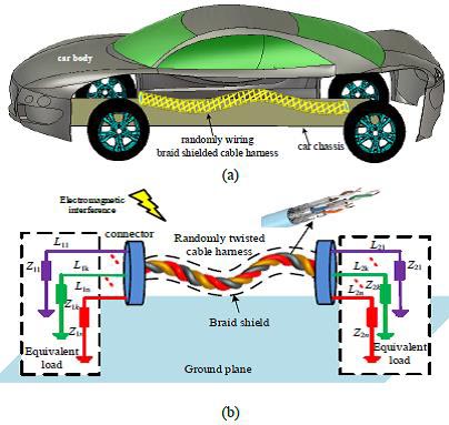
Figure 2: Schematic diagram and cross section of braid shielded automobile cable harness in randomly twisted bundling way. (a) Cable harness in automobile. (b) Schematic diagram.
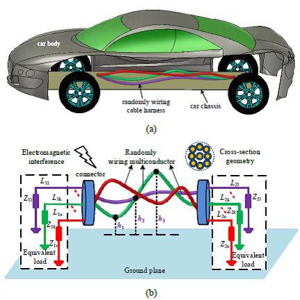
Figure 3: Schematic diagram and cross section of unshielded automobile cable harness in randomly wiring way. (a) Cable harness in automobile. (b) Schematic diagram.
II. THEORETICAL MODELING OF GENERALIZED ECBM
A. Statement of EM coupling to automotive cable harness with stochastic wiring factors
Figures 2(a) and 3(a), respectively, illustrate a typical model of braid shielded automotive cable harness in a randomly twisted bundling way and a model of unshielded cable harness with stochastic wiring factors. The corresponding schematic diagram and cross section can be seen in Figures 2(b) and 3(b). For the shielded cable harness, the geometric cross section remains the original shape along the cable length direction, while the relative position of the inner conductor changes. For the unshielded cable harness, the conductors are not exactly parallel and the position of the inner conductors is of uncertainty.
Considering the required computer resources, there is no possibility for the EM coupling problems of the whole cable harness to be solved. However, a solution that all the conductors are wired in a determined manner was put forward by the previous ECBM method to the immunity case, but it cannot be directly applied to the case where the cable harness is in a randomly wiring way. Therefore, this paper proposes a generalized ECBM method to reduce the randomly wiring automotive harness into a single-conductor model as demonstrated in Figure 4. That is, the EM coupling to the single conductor is equivalent to describe that on a complete cable harness model.
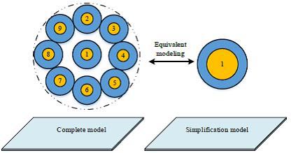
Figure 4: Cross-sectional geometry of the complete and simplification cable harness model.
B. Simplification modeling procedure
To simplify the cable harness with random wiring, this paper mainly discusses two stochastic wiring factors, including the relative position of the conductors within the cylindrical shielded structure and the height of the unshielded conductors to the ground.
This step aims at defining the inductance l and capacitance c of simplification cable in multiconductor transmission lines network
| (1) | |
| (2) |
where , ,
| (3) |
| (4) |
According to the MTLN theory, the per-unit-length capacitance parameters and of the simplification cable can be written as
| (5) |
| (6) |
where the conductors are numbered p, q, and n.
b) Case 1: Shielded Cable Harness in Randomly Twisted Way
Since the application of the randomly twisted way, the relative position of the inner conductor changes with the length direction of the cable. As shown in Figure 5, a schematic diagram of random transposition among conductors in a harness, the relative position of the inner conductors is uncertain, but they are limited to the connector plug-in at both ends of the cable harness where the terminals are determined. Cable harness has several adjacent segments of cable harness, and when the first segment is converted into the second segment, the positions of no. 3 conductor and no. 6 conductor are transformed. Also, with the second segment being converted into the third, the positions of no. 2 and no. 5 are transformed. Put simply, parameter matrix does not add any new element but only converts each other in element position.
Figure 5: Schematic diagram of transposition among conductors in a harness.
In this step, a random spline interpolation technique is applied to solve the discontinuity problem in the construction of cable harness model. At first, a number of randomly distributed coordinate points, conforming to Gaussian distribution, are generated. Then, the cable harness is divided into a series of homogeneous subsegments by the insertion of more points at other locations through spline interpolation. Finally, the piecewise polynomial form of cubic spline interpolation method is utilized to generate the cascade segments. After all these operations, a randomly twisted cable harness model can be determined.
It should be noted that the length of the subsegments should be up to one of the following two criteria: 1) Each subsegment length should be less than 1/10 of the minimum wavelength to ensure the spatial resolution of the highest frequency wave; 2) adequate subsegments (no less than 10) of the spline segment are inevitable for the continuity of the harness. Then, the smaller of the subsegments identified in the two criteria is adopted to generate the cascade subsegments through the usage of piecewise polynomial form of cubic spline interpolation technology.
Figure 6: n-conductors within a perfectly conducting cylindrical shield.
In Figure 6, a model of n-conductors with a radius of within a perfectly conducting cylindrical shield is displayed. The screen’s radius is denoted by and the distances of conductors from the shield axis are denoted by , whereas the angular separations of the conductors from the shield axis are denoted by . According to the study in [23], we can obtain
| (7) |
This step, aiming at generating the cross-sectional geometry of the equivalent cable mainly consists of two phases. The inductance and capacitance parameters are associated with the structural factors, such as the distance between the conductor and shield, and the relative distance among conductors. For this reason, the cross-sectional geometry parameters of equivalent model can be determined based on the knowledge of inductance .
1. Phase 1: Estimate the central distance d between the equivalent inner conductor and the central axis of the shield. d of equivalent conductor corresponds to the average of the distance of all the conductors at any location in the complete cable bundle model.
2. Phase 2: Estimate the radius of the equivalent cable. According to the analytical formula of self-inductance in eqn (7), the radius of each equivalent conductor can be approximated by
| (8) |
c) Case 2: Unshielded Cable Harness in Randomly Wiring Way
Figure 7(a) is an illustration of randomly wiring n-conductors located above an ideal conducting plane. In the figure, r and r represent the radius of any two conductors and h(z) refers to the height to the ground plane at position z along the cable length direction, which satisfies Gaussian distribution as demonstrated in Figure 7(b). The corresponding probability distribution of the height to ground is illustrated in Figure 7(c), in which S(z) is the conductor’s spacing and and stand for the insulation thickness of the conductor. According to study in [23], the calculation formula of per-unit-length inductance parameter can be written as
| (9) |
where , , , and . The diagonal element represents the self-inductance, while the off-diagonal element describes the mutual inductance. It can be seen from eqn (9) that the inductance parameters are related to the position of the conductors.
Figure 7: Randomly wiring unshielded n-conductors. (a) Double conductors above ideal conducting ground plane. (b) Wiring diagram of one of the conductors. (c) The probability distribution of the height to ground.
According to eqn (6) and (9), the per-unit-length capacitance parameter of the simplification cable model can be calculated and the geometric cross-sectional structure can be established with the corresponding radius r and the ground height h.
Calculation of r: According to eqn (6) and (9),r is
| (10) |
Calculation of h : The height of the simplified cable to the reference ground equals the average height of n-conductors to the ground at any cross section of the cable harness:
| (11) |

Figure 8: The full-wave simulation model of a shielded nine-conductor cable harness model and the corresponding simplification cable model in the automotive.
d) Equivalent Terminal Loads of Simplification Cable Model
This step aims at calculating the terminal loads of the equivalent model. Here, the equivalent CM loads are defined as the connection between conductor ends and the shield. The terminal load connected to the simplified cable end equals the loads at the end of all the conductors in parallel.
III. NUMERICAL VALIDATIONS
In this section, a model of braid shielded nine-conductor in randomly twisted bundling way and a model of unshielded nine-conductor with stochastic wiring in the automotive chassis are constructed for the validation of the proposed approach by CST Cable Studio with full-wave simulation. In this paper, the EM coupling value of the whole model is taken as the standard value, and the EM coupling value of the simplification model is compared.
A. Case 1: Shielded Cable Harness in Randomly Twisted Way in the Automotive
As shown in Figure 8, a nine-conductor point-point connected cable harness within a braid shielded cylindrical structure above the automotive chassis is modeled. All the conductors are bundled in a randomly twisted way. The wiring route is composed of stochastic locations and the corresponding coordinate value is listed in Table 1.
Table 1: Coordinate position of arbitrarily bent cable harness (unit: mm)
| Position | N | N | N |
|---|---|---|---|
| (x, y, z) | (0, 0, 60) | (200, 400, 10) | (400, -100, 20) |
| Position | N | N | N |
| (x, y, z) | (600, -100, 100) | (800, -200, 30) | (1200, -200, 10) |
| Position | N | – | – |
| (x, y, z) | (2000, 200, 40) | – | – |
Figure 9: Comparison of the CM current in frequency domain on complete cable harness model and equivalent cable model. (a) Near end. (b) Far end.
Each conductor has a radius of 0.5 mm and is surrounded by dielectric coating with a thickness = 1 mm and dielectric constant of and . The radius of the shield is 3 mm. The conductors with a serial number “2, 3, 4, 5, 6, 7, 8” in Figure 10 are evenly distributed on the circle with a radius of 2 mm. The terminal load connected to the ends of each conductor is 50 . The plane wave incident direction is along the Y-axis and the electric field direction is along the X-axis with an amplitude of 100 V/m as shown in Figure 8. The full-wave simulation model in CST is shown in Figure 9.
The cross-sectional geometry of simplification cable model is determined through the simplification procedure of case 1 described in Section 2.2. The corresponding r of the equivalent cable is 3.8 mm and the equivalent CM terminal loads are 5.6 .
The induced CM current at the near and far ends of complete cable harness and simplification cable in frequency domain are calculated through the method of CST Cable Studio with full-wave simulation. Based on the co-simulation technique, the TLM technique and AC result solver are, respectively, adopted in the existing numerical approach to analyze the electric field around the conductors and compute the coupling to terminal loads.
In Figure 9, a comparison between the CM currents obtained at the ends of the complete cable harness model and the simplification cable model over frequency (0.200 MHz) is clearly demonstrated. The red line represents the simulation results of the complete cable model, while the black line describes that of the simplification model. The good agreement indicates a validation of the proposed method.
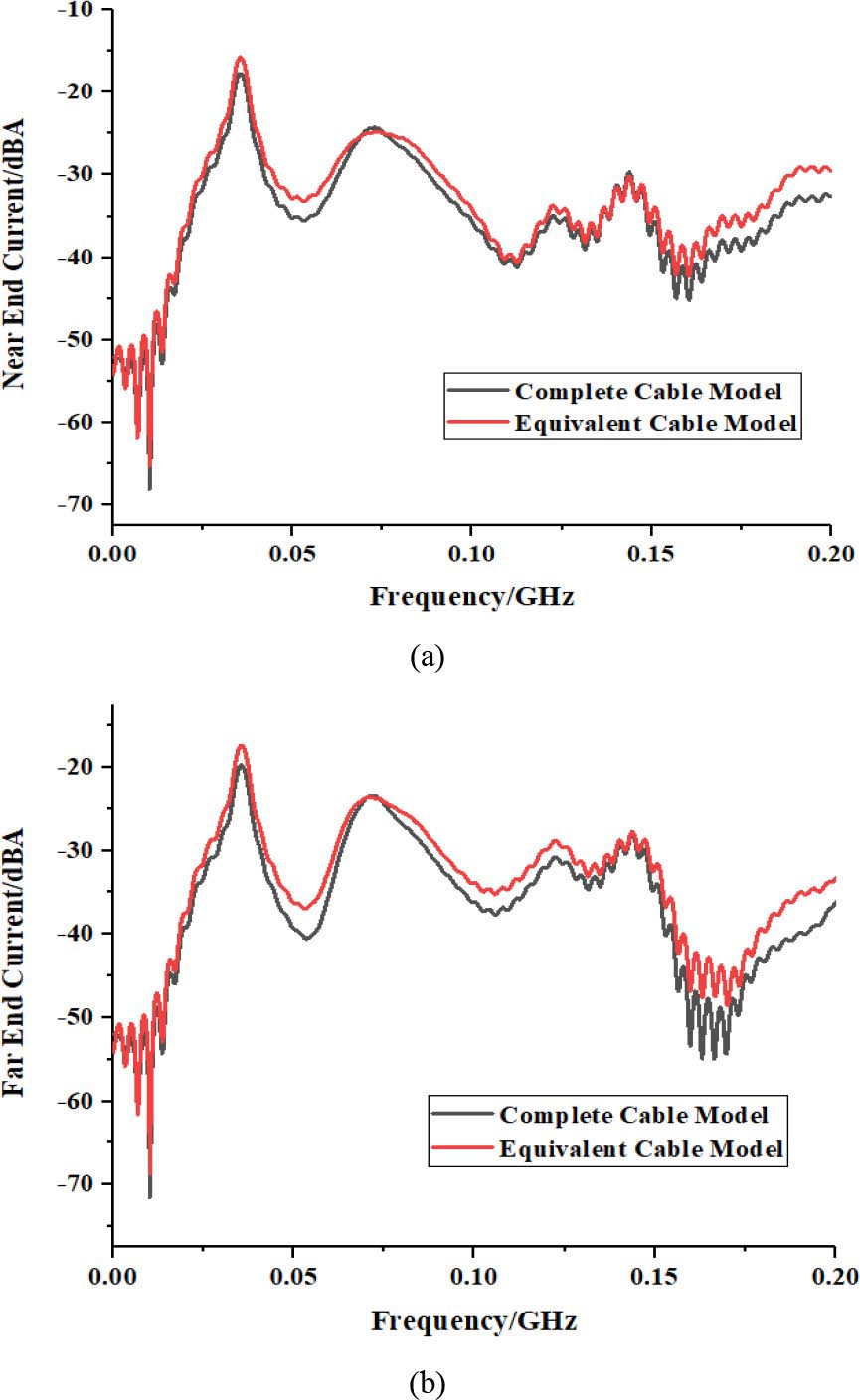
Figure 10: Comparison of the CM current in frequency domain on complete cable harness and equivalent cable. (a) Near end. (b) Far end.
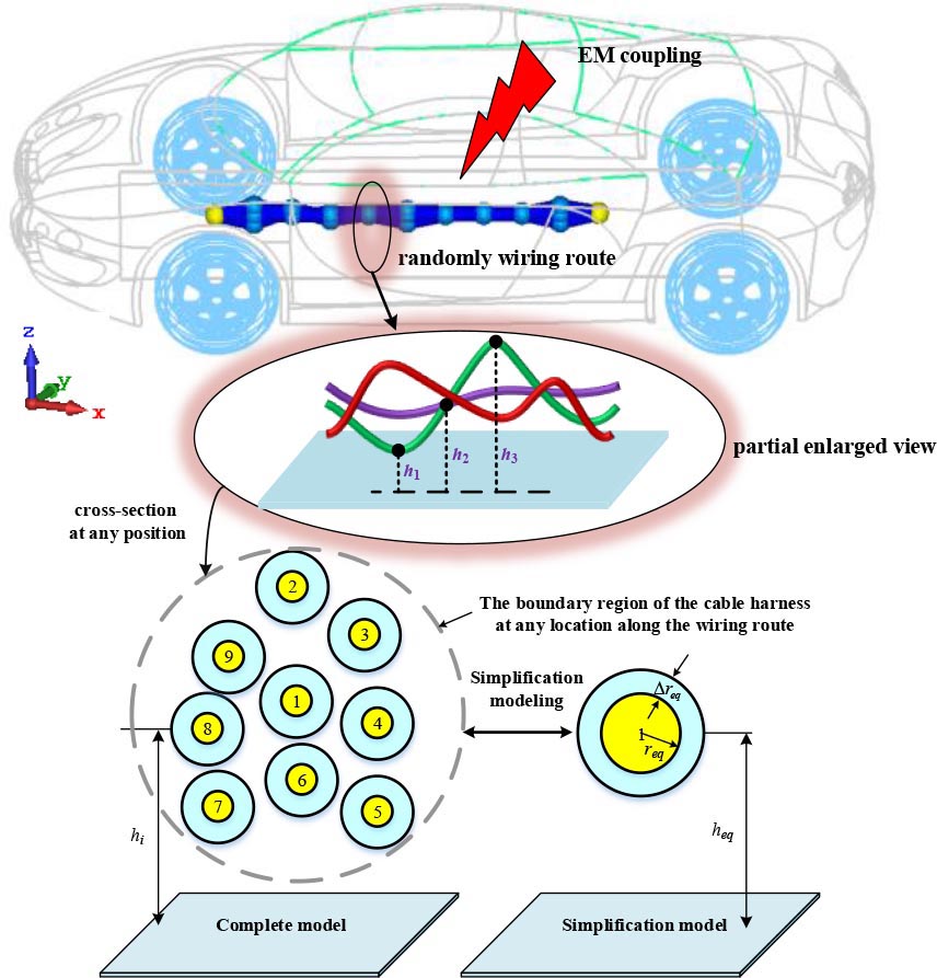
Figure 11: The full-wave simulation model of an unshielded nine-conductor cable harness model and the corresponding simplification cable model in the automotive.
B. Case 2: Unshielded Cable Harness with Stochastic Wiring in the Automotive
The full-wave simulation model in CST is shown in Figure 10, and a nine-conductor point-point connected unshielded cable harness above the automotive chassis is modeled and all of the conductor is wired in a randomly bundling way. The wiring route consists of a number of random locations. Each conductor, with a radius of 0.5 mm, is surrounded by dielectric coating with a thickness =1 mm and dielectric constant of and , and the terminal load connected to the ends of each conductor is 50.The plane wave incident direction is along the Y-axis and the electric field direction is along the X-axis with an amplitude of 100 V/m.
Under the simplification procedure of case 2 described in Section 2-B, the randomly wiring route and cross-sectional geometry of simplification cable model is determined. The radius of equivalent conductor is 4 mm and the thickness of corresponding insulation layer is 1mm.
The comparison results of the coupling current on near end and far end of the complete cable harness model and simplification cable model over frequency (0.200 MHz) are, respectively, shown in Figures 11(a) and (b), which proves the efficacy of the proposed method. As it is seen in the figure, the red line represents the result of the complete cable model, while the black line describes that of the simplification model.
IV. CONCLUSION
This paper proposes a generalized simplification technique to model the EM illumination on automotive cable harness with stochastic wiring factors. The combination of the conductors contributes to the simplification of modeling the complete cable harness.
The randomly wiring problem in generating the cross-sectional geometrical parameters of the simplification cable model is successfully solved by the application of the Gaussian distribution and spline interpolation, which are used to determine the route of cable harness. As the position of the conductors within the harness is related to the inductance and capacitance parameters, the inductance and capacitance matrixes of the cable harness at different locations are established by the utilization of transposition relationship between the subsegments of the conductors. To this end, the generalized simplification modeling technique is developed to determine the electrical and geometrical parameters of the simplification cable. Furthermore, a model of braid shielded nine-conductor with random twisting and a model of unshielded nine-conductor with random wiring above automotive chassis are constructed to validate the proposed method by CST Cable Studio with full-wave simulation.
REFERENCES
[1] D. Ren, W. W. Ruan, P. Xiao, P. A. Du, J. H. Deng, K. M. Zhou, “An analytical method of minimizing the crosstalk of curved cable and determining the optimal wiring,” Applied Computational Electromagnetics Society (ACES) Journal, vol. 35, no. 7, pp. 742-749, Jul. 2020.
[2] P. Xiao, W. W. Ruan, P. A. Du, “An analytic method of determining a critical cable spacing for acceptable crosstalk,” Applied Computational Electromagnetics Society (ACES) Journal, vol. 35, no. 2, pp. 237-244, Feb. 2020.
[3] H. Chen and T. Wang, “Estimation of common-mode current coupled to the communication cable in a motor drive system,” IEEE Transactions on Electromagnetic Compatibility, vol. 60, no. 6, pp. 1777-1785, Mar. 2018.
[4] F. Rachidi. “A review of field-to-transmission line coupling models with special emphasis to lightning-induced voltages on overhead lines,” IEEE Transactions on Electromagnetic Compatibility, vol. 54, no. 4, pp. 898-911, Feb. 2012.
[5] Q. Jin, W. Sheng, C. Gao, and Y. Yan, “Internal and external transmission line transfer matrix and near-field radiation of braided coaxial cables,” IEEE Transactions on Electromagnetic Compatibility, vol. 63, no. 1, pp. 206-214, Aug. 2021.
[6] Y. Hakuta, T. Watanabe, T. Takenaka, T. Ito, and A. Hirata, “Safety standard compliance of human exposure from vehicle cables using coupling factors in the frequency range of 0.3–400 kHz,” IEEE Transactions on Electromagnetic Compatibility, vol. 63, no. 1, pp. 313-318, Apr. 2021.
[7] J. He, Z. Guo, and X. Li, “Mechanism model and prediction method of common mode radiation for a nonisolated very-high-frequency DC–DC converter with cables,” IEEE Transactions on Power Electronics, vol. 35, no. 10, pp. 10227-10237, Mar. 2020.
[8] Y. Zhang, S. Wang, and Y. Chu. “Investigation of radiated electromagnetic interference for an isolated high-frequency DC–DC power converter with power cables,” IEEE Transactions on Power Electronics, vol. 34, no. 10, pp. 9632-9643, Jan. 2019.
[9] B. X. Zhang, P. Xiao, D. Ren, and P. A. Du, “An analytical method for calculating radiated emission of discontinuous penetrating cable,” Applied Computational Electromagnetics Society (ACES) Journal, vol. 34, no. 1, pp. 25-32, Jan. 2019.
[10] Y. Cai, Y. Guan, W. Liu, and J. He, “Study of transient enclosure voltage coupling to secondary cables in a gas-insulated substation,” IEEE Transactions on Power Delivery, vol. 33, no. 2, pp. 761-768, Mar. 2017.
[11] Y. S. Xiao, D. Ren, P. Xiao, and P. A. Du, “An equivalent modeling method for the radiated electromagnetic interference of PCB based on near-field scanning,” Applied Computational Electromagnetics Society (ACES) Journal, vol. 34, no. 5, pp. 784-791, May 2019.
[12] D. Zhang, Y. Wen, J. Zhang, and G. Xin, “Coupling analysis for shielded cables in the train using hybrid method,” IEEE Access, vol. 7, no. 1, pp. 76022-76029, Jun. 2019.
[13] M. Wu, D. G. Beetner, T. H. Hubing, H. Ke, and S. Sun, “Statistical prediction of “Reasonable Worst-Case” crosstalk in cable bundles,” IEEE Transactions on Electromagnetic Compatibility, vol. 51, no. 3, pp. 842-851, Aug. 2009.
[14] M. Alibakhshi-Kenari, M. Naser-Moghadasi, R. A. Sadeghzadeh, B. S. Virdee, and E. Limiti, “Traveling-wave antenna based on metamaterial transmission line structure for use in multiple wireless communication applications,” AEU-International Journal of Electronics and Communications, vol. 70, no. 12, pp. 1645-1650, Dec. 2016.
[15] E. Genender, H. Garbe, and F. Sabath, “Probabilistic risk analysis technique of intentional electromagnetic interference at system level,” IEEE Transactions on Electromagnetic Compatibility, vol. 56, no. 1, pp. 200-207, Jul. 2014.
[16] G. Ala, M. C. Di Piazza, G. Tine, F. Viola, and G. Vitale, “Evaluation of radiated EMI in 42-V vehicle electrical systems by FDTD simulation,” IEEE Transactions on Vehicular Technology, vol. 56, no. 2, pp. 1477-1484, Jul. 2007.
[17] R. G. Jobava, A. L. Gheonjian, J. Hippeli, G. Chiqovani, D. D. Karkashadze, F. G. Dogdanov, and Khvitia B. Bzhalava, “Simulation of low-frequency magnetic fields in automotive EMC problems,” IEEE Transactions on Electromagnetic Compatibility, vol. 56, no. 6, pp. 1420-1430, Jun. 2014.
[18] N. Mora, F. Rachidi, P. Pelissou, and A. Junge, “Numerical simulation of the overall transfer impedance of shielded spacecraft harness cable assemblies,” IEEE Transactions on Electromagnetic Compatibility, vol. 57, no. 4, pp. 894-902, Mar. 2015.
[19] G. Andrieu, L. Kone, F. Bocquet, B. Parmantier, J. P. “Multiconductor reduction technique for modeling common-mode currents on cable bundles at high frequency for automotive applications,” IEEE Transactions on Electromagnetic Compatibility, vol. 50, no. 1, pp. 175-184, Feb.2008.
[20] G. Andrieu, A. Reineix, M. Bunlon, J. P. Parmantier, and B. Demoulin, “Extension of the “equivalent cable bundle method” for modeling electromagnetic emissions of complex cable bundles,” IEEE Transactions on Electromagnetic Compatibility, vol. 51, no. 1, pp. 108-118, May 2009.
[21] Z. Li, L. L. Liu, J. Yan, Z. Y. Nie, and C. Q. Gu, “An efficient simplification scheme for modeling crosstalk of complex cable bundles above an orthogonal ground plane,” IEEE Transactions on Electromagnetic Compatibility, vol. 55, no. 5, pp. 975-978, May 2013.
[22] B. Schetelig, “Simplified modeling of EM field coupling to complex cable bundles,” Advances in Radio Science, vol. 8, no. 13, pp. 211-217, Jan. 2010.
[23] C. R. Paul, Analysis of Multiconductor Transmission Lines, 2nd ed. Hoboken, NJ, USA: Wiley, 2007.
BIOGRAPHIES

Pei Xiao was born in Shaoyang, Hunan province, China, in 1989. He received the bachelor’s and Ph.D. degrees in mechanical engineering from the University of Electronic Science and Technology of China (UESTC), Chengdu, China, in 2013 and 2019, respectively.
He is currently a Postdoctoral Research Fellow with Hunan University. His research interests are numerical computation, theoretical electromagnetic analysis including the antennas, EMC/EMI in multiconductor transmission line, power electronic device, and electric vehicle.
Jiawei Li was born in Yueyang, Hunan province, China, in 1997. He received the bachelor’s degree from the College of Physics and Information Engineering, Fuzhou University, Fuzhou, China, in 2019. He is currently working toward the postgraduate degree with the College of Electrical and Information Engineering, HunanUniversity.
His research interest includes EMC.

Chao Zhang was born in Huaihua, Hunan province, China, in April 1991. He received the B.S. degree in communication and information engineering from Huaihua College in 2014 and the M.S. degree in electromagnetic field and microwave technologies from Shanghai University in 2018. He is currently working toward the Ph.D. degree in electronic science and technology with Hunan University, Changsha, China.
He has authored or co-authored more than 10 research papers in international academic journals and international conferences. His current research interests include antenna technology, EMC, and plasmonic metamaterials and devices at microwave and terahertz frequencies.

Jinxin Li received the B.S. degree in electronic information science and technology in 2008 and the Ph.D. degree in electromagnetic field and microwave technology in 2017 from the University of Electronic Science and Technology of China (UESTC), Chengdu, China. From 2015 to 2016, he was a Visiting Ph.D. Student with the
Department of Electrical and Computer Engineering, Duke University, Durham, NC, USA.
He has been an Assistant Professor with Hunan University since 2017. His research interests include antennas, antenna arrays, metamaterials, and passive devices and circuit.

Gaosheng Li (Senior Member, IEEE) received the B.S. degree in electromagnetic field and microwave and the M.S. and Ph.D. degrees in electronic science and technology from the National University of Defense Technology (NUDT), Changsha, China, in 2002, 2004, and 2013, respectively.
He was with NUDT as a Teaching Assistant from 2004 to 2006, a Lecturer from 2006 to 2011, and then as an Associate Professor from 2011 to 2017. He joined Hunan University as a Professor in 2018. From 2014 to 2016, he was with the Nanjing University of Aeronautics and Astronautics (NUAA) and Wuxi Huace Electronic Systems Co., Ltd., China as a Postdoctoral Research Fellow. From 2016 to 2017, he was a Visiting Scholar with the University of Liverpool (UoL), U.K., sponsored by China Scholarship Council (CSC). His research interests include antennas and propagation (AP), electromagnetic compatibility (EMC), wireless propagation, and microwave systems.
Prof. Li is the author or coauthor of 7 books and 150 papers published in journals and conference proceedings. He owns 30 Chinese patents and 10 software copyrights. He won three national scientific prizes in 2008, 2013, and 2015, respectively. He is now a Senior Member (2019) of the IEEE AP Society and EMC Society, a Member (2016) of IET, a Member (2017) of ACES, a Member (2011) of IEICE, as well as a Senior Member (2014) of the Chinese Institute of Electronics (CIE).
ACES JOURNAL, Vol. 37, No. 3, 311–319.
doi: 10.13052/2022.ACES.J.370308
© 2021 River Publishers