Quad-band Compact MIMO Antennas for 5G Mobile Communications
Asmaa E. Farahat and Khalid F. A. Hussein
1Microwave Engineering Department, Electronics Research Institute, Cairo, 11843, Egypt
asmaa@eri.sci.eg, fkhalid@eri.sci.eg
Submitted On: March 25, 2022; Accepted On: September 20, 2022
Abstract
Three types of quad-band millimetric-wave two-port MIMO antenna systems are proposed for the forthcoming generations of mobile handsets. A novel printed antenna is introduced to be the single element of the proposed MIMO antennas. It is shown that the proposed MIMO antennas are capable of producing both spatial and polarization diversities that enhance the performance of mobile communications. Two configurations of co-polarized two-port MIMO antennas are proposed to provide spatial diversity, whereas a cross-polarized two-port MIMO antenna is proposed to produce polarization diversity. It is shown that all the proposed MIMO antennas can operate efficiently over the four frequency bands centered at 28, 43, 52, and 57 GHz. Prototypes are fabricated for the proposed MIMO antennas for the sake of experimental evaluation. The measurements agree with the simulation results showing high performance of the proposed types of MIMO antennas including the impedance matching, radiation patterns, envelop correlation coefficient, and diversity gain. Both the experimental and simulation results show that the achieved bandwidths, at the four operational frequency bands, are 0.6, 0.6, 1.8, and 1.5 GHz, respectively. Also, the radiation efficiencies calculated at the four operational frequencies are 86.5%, 87.5%, 89.2%, and 90.0%, respectively. The dimensions and the results concerning the performance of the proposed MIMO antennas are compared to other designs for MIMO antennas available in some recently published work.
Index Terms: 5G, MIMO antennas, quad-band.
1 INTRODUCTION
One of the essential demands for future generations of mobile communications is the capability of mobile handsets to transfer data at very high speeds. A mobile handset antenna should have a compact profile and simple structure [1, 2]. To meet the standards of long-term-evolution (LTE) and fifth-generation (5G) mobile communications [3] the handheld device’s antenna should provide broadband operation, high data rate, and low power consumption. This recommends that a mobile handset antenna should be able to operate in the range of mm-wave of the electromagnetic spectrum to support the required data rates for future applications. Moreover, due to size limitations, it is recommended that a mobile handset antenna is able to operate efficiently at multiple frequency bands in the mm-wave spectrum to support the applications of the forthcoming mobile generations [4, 5]. In various situations, the antenna structure may be complicated as those having a three-dimensional shape to operate efficiently in a single frequency band and to perform some function in special applications [6, 7] and may include layers with high electromagnetic absorbance [8] to produce radiation patterns of the desired shape. However, for mobile handsets, due to size and weight limitations, it is preferable to have a planar antenna of simple-structure, multi-band operation, and omnidirectional radiation patterns.
The design of MIMO antenna systems for operation in mobile handsets for the next generations of mobile communications faces many challenges. First of all, the MIMO antenna on a handset should be miniaturized due to space limitations. The second challenge is to achieve high isolation between the antenna elements in spite of the small area available for the antenna on the mobile handset. The third challenge is to have the MIMO antenna operational at multiple frequencies with enough wideband at each frequency (multiple-band operation). The fourth challenge is to produce the required shape of the radiation patterns over the operational frequency bands. Also, it may be required from a MIMO antenna to provide many types of diversity such as spatial, polarization, and pattern diversities.
Various types of MIMO antenna systems for 5G mobile handsets, recently, have been designed in a lot of research articles. For example, in [9], a compact microstrip line fed dual-band printed two-port and four-port MIMO antennas are proposed for wireless communications. In [10], a seven-port MIMO antenna system is proposed as a candidate for future mobile communications to operate at 37.5 GHz. A cross-polarized four-port dual-band MIMO antenna array is proposed in [11] to operate at 28 and 37.5 GHz for 5G communications. The work of [12] proposes a dual-band two-port MIMO antenna to operate at 28 and 38 GHz for 5G mobile applications. In [13], a planar dual-band (27/39 GHz) millimeter-wave two-port MIMO antenna is suggested for 5G mobile communications. The work of [14] introduces a compact four-port MIMO antenna with high isolation and a single wideband for mm-Wave Applications. In [15] and [16], quad-band () two-port and four-port MIMO antenna systems are proposed for 5G mobile communications. The work of [17] proposes a dual-band (28/38 GHz) four-port MIMO antenna system for 5G mobile communications for efficient Estimation of the directional of arrival in noisy communication channels. In [18] and [19], dual-Band (28/38 GHz) cross-polarized four-port MIMO antenna systems composed of high-gain Yagi-Uda antenna with corrugated radiators and enhanced reflectors are proposed to provide spatial, polarization, and pattern diversities for 5G mobile communications.
In this work, compact-size quad-band two-port MIMO antenna systems are proposed to operate in the millimetric-wave bands (28/43/52/57 GHz) for the forthcoming generations of mobile communications. The proposed MIMO antennas provide various types of diversity to enhance the performance of mobile communication systems. Two types of co-polarized two-port MIMO antenna systems with high isolation among the antenna elements are proposed to provide spatial polarization. Also, a cross-polarized two-port MIMO antenna is proposed to provide polarization diversity.
2 DESIGN OF THE QUAD-BAND SINGLE-ELEMENT ANTENNA
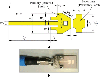
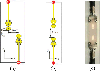
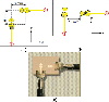
The geometry of the patch antenna proposed to construct the MIMO antenna systems is demonstrated in Fig. 1. It is designed to be printed on Rogers RO3003 substrate with and 0.25 mm thickness, dielectric constant = 3, and loss tangent . The substrate has a solid ground plane to reduce the back radiation from the antenna. The printed antenna is fed through a 50 microstrip line of length . The width of the microstrip line is set to to achieve its characteristic impedance equal to . An inset feed is used to match the antenna impedance to . The inset length is and the width of each slot made on the sides of the feeding line for the inset feed is . The remaining dimensions are listed in Table 1.
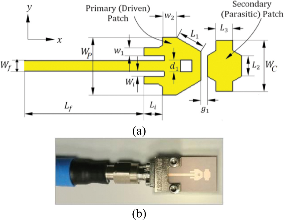
Figure 1: The quad-band millimetric-wave antenna proposed for MIMO antenna systems. (a) Geometry of the printed antenna. (b) Fabricated antenna prototype is connected to end launcher and coaxial cable for measurements.
Table 1: Dimensions of the quad-band printed antenna proposed for the MIMO antenna system
| Dimension | ||||||||||
| Value (mm) | 1.7 | 1.2 | 1 | 0.3 | 0.45 | 0.85 | 0.7 | 0.38 | 3.4 | 3.0 |
In the electromagnetic simulations, for a substrate of size 8 mm18 mm and height 0.25 mm, the simulation (execution) time for each of the studied cases to reach the final design is approximately 10 minutes with accuracy 40 dB using the time domain solver on a core I7-3.6 GHz processor, 16G RAM, and 64-bit operating system. Hexahedral meshing is used to model the design with 15 cells/wavelength for allsimulations.
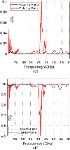
The millimetric-wave antenna with the geometry shown in Fig. 1 and the dimensional parameters listed in Table 1 is used to construct various configurations of two-port MIMO antenna systems with various types of diversity proposed for the handsets of the forthcoming generations of mobile communications. Accordingly, it is important to investigate the characteristics of this antenna through electromagnetic simulation and laboratory measurements. Figure 2 presents the dependence of the scattering parameter at the antenna port as obtained by both simulation and experimental measurements. It is shown that the antenna has four operational millimetric-wave frequency bands at which the antenna is matched to feeder and, hence, the return loss is very low. The operational frequency bands are 28, 43, 52, and 57 GHz. Fortunately the four frequencies are distributed over very important range of the millimetric-wave which makes this antenna a promising candidate for future mobile applications. Both the simulation results and the measurements come in good agreement with each other.
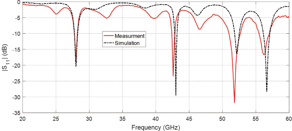
Figure 2: Dependence of on the frequency for the proposed quad-band patch antenna.
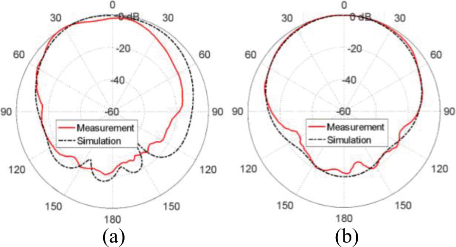
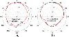
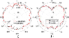
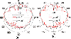
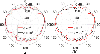
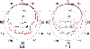
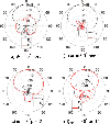
Figure 3: Radiation patterns of the proposed quad-band patch antenna at 28 GHz in the planes (a) and (b) .
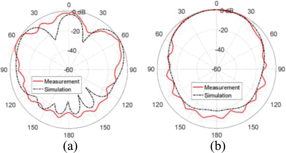
Figure 4: Radiation patterns of the proposed quad-band patch antenna at 43 GHz in planes (a) and (b) .
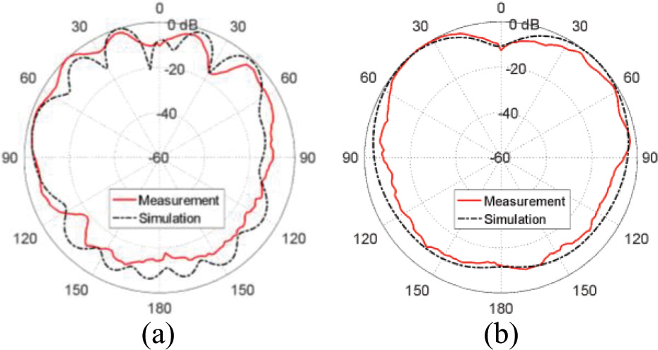
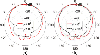
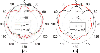
Figure 5: Radiation patterns of the proposed quad-band patch antenna at 53 GHz in planes (a) and (b) .
The elevation radiation patterns in the planes and at the four frequencies 28, 43, 52, and 57 GHz are presented in Figs. 3, 4, 5, and 6, respectively. The experimental measurements show good agreement with the simulation results at all the operational frequencies of the proposed antenna.
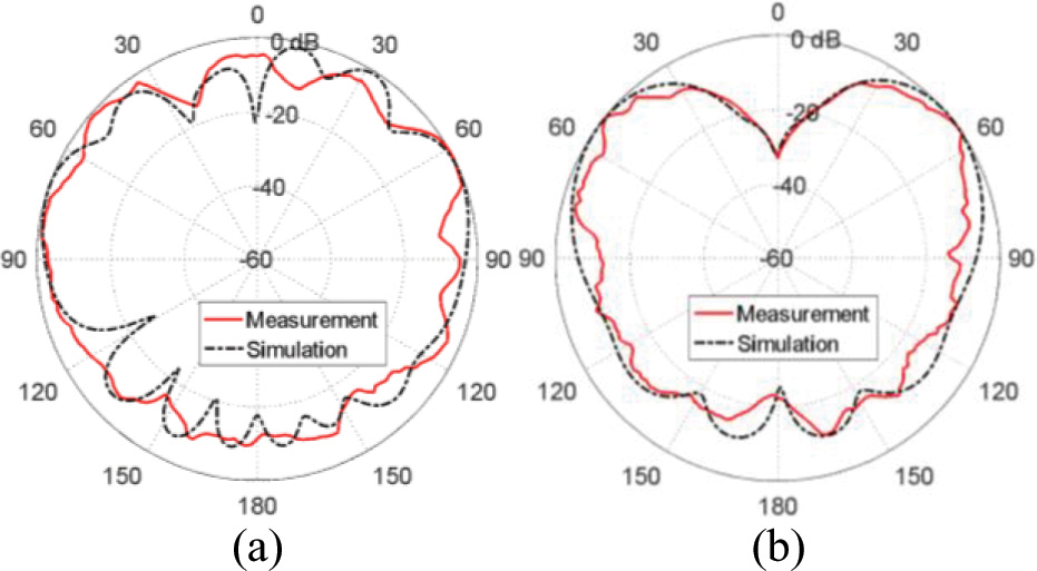
Figure 6: Radiation patterns of the proposed quad-band patch antenna at 56.5 GHz in planes (a) and (b) .
3 TWO-PORT MIMO ANTENNAS FOR QUAD-BAND OPERATION
Printed MIMO antennas are recommended for future generations of mobile handsets to enhance the performance of the mobile communication systems by providing various types of antenna diversity such as spatial, polarization, and pattern diversity. Due to space and power limitations in a mobile handset, two-port MIMO antennas are appropriate and may be the most suitable solution among the other MIMO antenna systems to provide the required types of diversity. The present section provides various designs of two-element MIMO antennas. The proposed MIMO antennas are fabricated and subjected to experimental evaluation. The simulation and experimental results are compared to each other for the confirmation of the obtained results.
3.1 Co-polarized two-port MIMO antennas for spatial diversity
Keeping large enough distance between two antennas of the same polarization on the mobile handset provides spatial diversity that can mitigate fading problems due to multipath propagation in wireless communication channels.
In the present section, three types of co-polarized two-port MIMO antennas using the single-element antenna shown in Fig. 1 are investigated theoretically and experimentally. Each of the three types of the proposed two-port MIMO antenna is described and its performance is investigated in the following subsections. In spite of being of almost equal performance, the three types have different dimensions and are proposed to provide a variety of solutions that can fit the available space on the electronic board of a specific mobile handset.
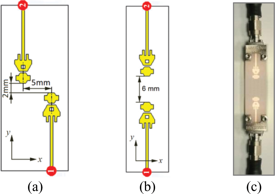
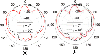
Figure 7: Two types of two-port MIMO antenna system constructed as two elements of the quad-band patch element. (a) Model with shifted antennas. (b) Model with face-to-face arrangement. (c) Fabricated prototype connected to end launchers and coaxial cables for measurements.
A.1. Design and fabrication of co-polarized two-port MIMO antennas
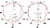
The patches of the first type of the proposed two-port MIMO antennas were arranged as shown in Fig. 7 (a). To reduce the mutual coupling, the two patch antennas were horizontally shifted from each other such that the space between their axes was 5 mm. However, the vertical separation between the two antennas was only 2 mm. For a more compact MIMO antenna, the patches of the second MIMO configuration were arranged face-to-face as shown in Fig. 7 (b). The patches of the third MIMO system were arranged side-by-side as shown in Fig. 8 (a). A prototype was fabricated for each type of the MIMO antenna systems as shown in Figs. 7 (c) and 8 (b), respectively, and connected to a coaxial feeder using coaxial end launchers for experimental assessment. It should be noted that the patch of all the proposed types of MIMO antennas were well-matched to the feeder and, on the other hand, the feeding microstrip line was well-designed to have its characteristic impedance equal to . Consequently, the length of the feeding microstrip lines could be variable without affecting antenna performance. For this reason, the length of the feeding line was not considered as a part of the antenna structure and, hence, the lengths of all the feeding lines are excluded from the antenna dimensions.
A.2. Mutual coupling between the antenna elements and the diversity gain
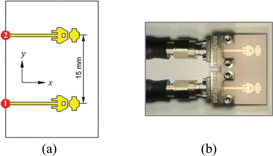
Figure 8: Two-port MIMO antenna system constructed as two elements of the quad-band patch arranged side-by-side. (a) Antenna model for simulation. (b) Fabricated prototype connected to end launchers and coaxial cables for measurements.
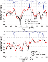
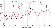
The self and mutual S-parameters of the co-polarized two-port MIMO antenna systems whose designs are presented in Figs. 7 and 8 have their frequency dependencies as shown in Figs. 9 (a) and 9 (b), respectively. The results were obtained by electromagnetic simulation using the commercially available CST simulator. When comparing the frequency dependencies of the self S-parameters of the two-port MIMO antennas to those presented in Fig. 2, for the single-element antenna, it is clear that the locations of the resonant frequencies (anti-peaks of and with the frequency) for the two configurations of MIMO antennas were almost identical to those of the single-element antenna. This indicates that the mutual coupling between the two antennas is very weak for the face-to-face as well as the side-by-side MIMO configurations. This is emphasized by the low magnitude of the mutual S-parameter, over the entire frequency range (20–60 GHz) as shown in Fig. 9 for both two-port MIMO configurations. Microwave measurements are used to confirm the low mutual coupling between the antenna ports. The VNA of Rhode and Schwartz model ZVA67 is used to evaluate the reflection coefficients, and , and the mutual S-parameters, and , for the fabricated prototypes of the proposed MIMO antennas. The dependence of on the frequency over the range (20–60 GHz) obtained by the CST simulator is compared to that obtained by experimental measurements as shown in Fig. 9. Both come in good agreement and confirm low mutual coupling between the antenna ports.
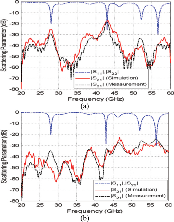
Figure 9: Frequency dependence of the self and mutual S-parameters of the co-polarized two-port MIMO antenna systems. (b) Face-to-face configuration shown in Fig. 7. (a) Side-by-side configuration shown in Fig. 8.
A.3. Envelope correlation coefficient and diversity gain of the co-polarized two-port MIMO antenna
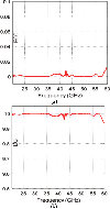
As a consequence of low mutual coupling and the distance between the two-ports of the co-polarized MIMO antennas, the ECC is very low over the entire frequency range (20-60 GHz) and is almost zero over the operational frequency bands (28, 43, 52, 57 GHz) as shown in Fig. 10 (a). The corresponding DG is almost 10 as shown in Fig. 10 (b).
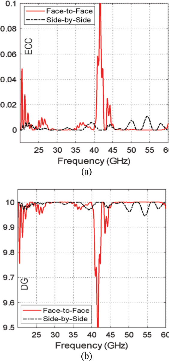
Figure 10: Frequency dependence of the ECC and DG of the co-polarized two-port MIMO antenna systems with the two arrangements presented in Figs. 7 and 8.
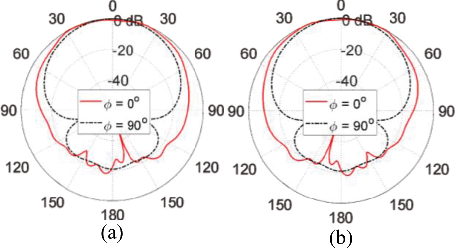
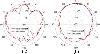
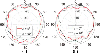
Figure 11: Radiation patterns in the elevation planes for the co-polarized face-to-face two-port MIMO antenna system at 28 GHz when excited at (a) port 1, (b)port 2.
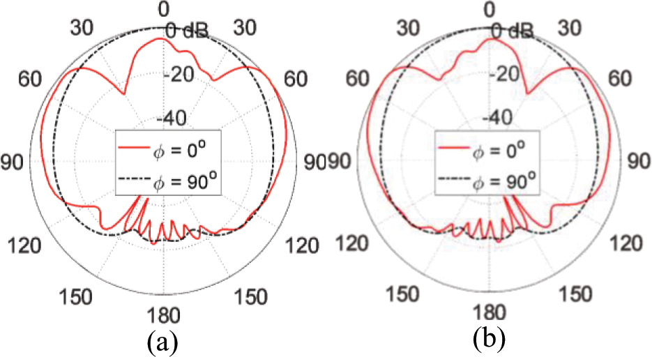
Figure 12: Radiation patterns in the elevation planes for the co-polarized face-to-face two-port MIMO antenna system at 43 GHz when excited at (a) port 1, (b)port 2.
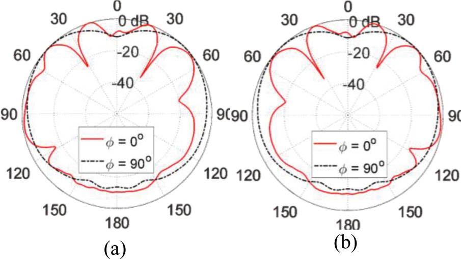
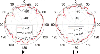
Figure 13: Radiation patterns in the elevation planes for the co-polarized face-to-face two-port MIMO antenna system at 52 GHz when excited at (a) port 1, (b)port 2.
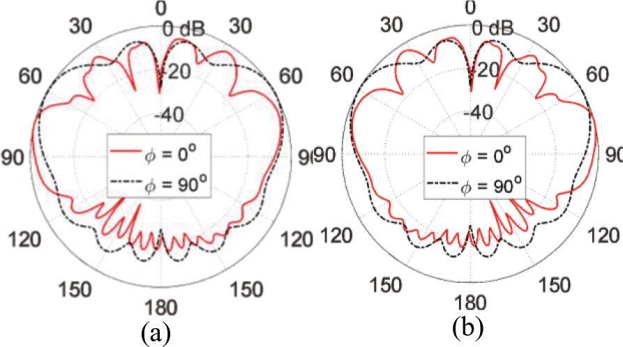
Figure 14: Radiation patterns in the elevation planes for the co-polarized face-to-face two-port MIMO antenna system at 57 GHz when excited at (a) port 1, (b)port 2.
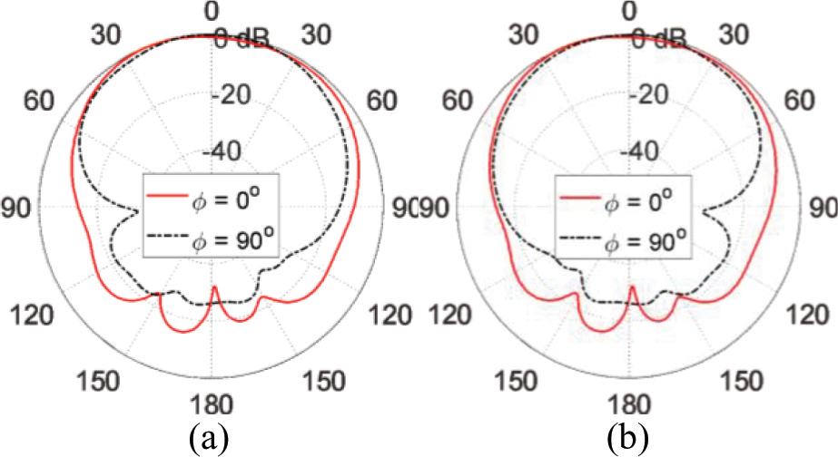
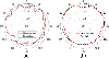
Figure 15: Radiation patterns in the elevation planes for the co-polarized side-by-side two-port MIMO antenna system at 28 GHz when excited at (a) port, (b)port 2.
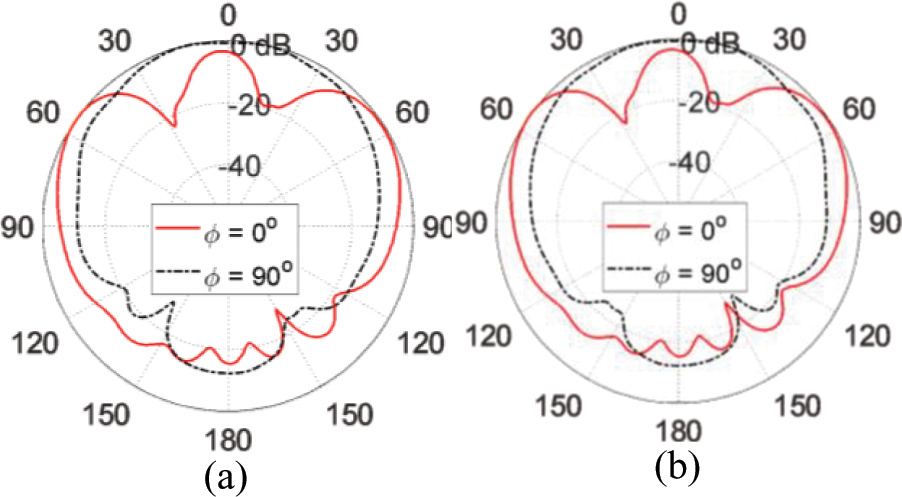
Figure 16: Radiation patterns in the elevation planes for the co-polarized side-by-side two-port MIMO antenna system at 43 GHz when excited at (a) port, (b)port 2.
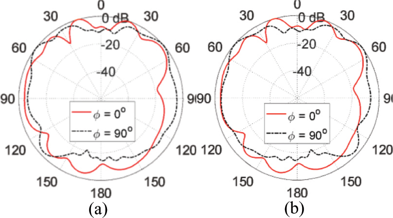
Figure 17: Radiation patterns in the elevation planes for the co-polarized side-by-side two-port MIMO antenna system at 52 GHz when excited at (a) port, (b) port 2.
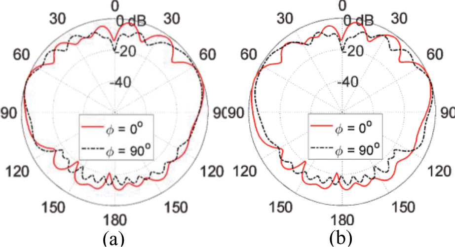
Figure 18: Radiation patterns in the elevation planes for the co-polarized side-by-side two-port MIMO antenna system at 57 GHz when excited at (a) port, (b) port 2.
A.4. Radiation patterns of co-polarized two-port MIMO antenna system
The radiation patterns of the co-polarized two-port MIMO antenna in the elevation planes and at the operational frequencies (28, 43, 52, 57 GHz) are presented in Figs. 11, 12, 13, and 14, respectively, for face-to-face configuration, and Figs. 15, 16, 17, and 18, respectively, for the side-by-side configuration, as obtained by simulation when the MIMO antenna is fed through each port alone. The corresponding values of the maximum gain are 7.1, 8.1, 7.7, and 8.6 dBi, respectively, for the face-to-face configuration, and 6.89, 7.9, 7.6, and 8.3 dBi, respectively, for the side-by-side configuration. The radiation patterns and the achieved gain values at the four operational frequencies seem to be appropriate for various wireless communications and mobile applications.
3.2 Two-port MIMO antennas for polarization diversity
The simplest form of cross-polarized MIMO antenna can be realized by combining pairs of antennas with orthogonal polarizations (i.e. horizontal/vertical, slant 45, left-hand/Right-hand circular polarization, etc.). Such cross-polarized MIMO antenna systems areable to provide polarization diversity that enhances mobile communication performance.
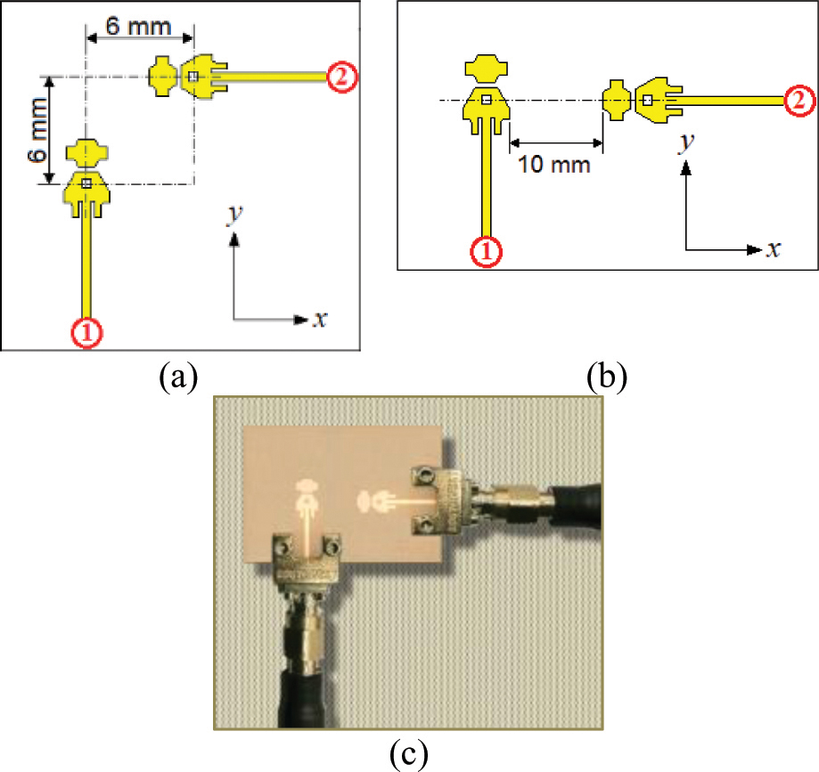
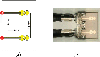
Figure 19. (a): Cross-polarized two-port MIMO antenna system constructed as two orthogonally oriented elements of the quad-band patch. (a) Antenna model for simulation. (b) Fabricated prototype connected to end launchers and coaxial cables for measurements.
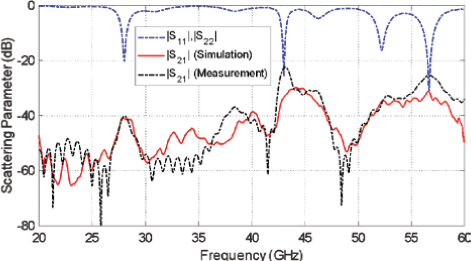
Figure 19. (b): Frequency dependence of the self and mutual scattering parameters of the cross-polarized two-port MIMO antenna system presented in Fig. 15 (a).
B.1. Design and fabrication of cross-polarized two-port MIMO antenna
A cross-polarized two-port MIMO antenna that produces two orthogonal polarizations when fed at port 1 and port 2 can be constructed as shown in Fig. 19. (a) using the single-Element antenna introduced in Section II. When this MIMO antenna is excited at port 1, the electric field in the far zone is -oriented whereas the excitation at port 2 produces -oriented electric field in the far zone.
B.2. Mutual coupling between the antenna elements
The self and mutual S-parameters of the cross-polarized two-port MIMO antenna system (presented in Fig. 19. (a)) have their frequency dependencies as shown in Fig. 19. (b). As obtained by simulation, the frequency dependence of of the cross-polarized two-port MIMO antenna is identical to that of . It is clear that the minima of and with the frequency occur at almost the same resonant frequencies of the single-element antenna (See Fig. 5). This indicates that the mutual coupling between the two elements of the cross-polarized MIMO antenna is very weak. Also, the magnitude of the mutual scattering coefficient is very low over the entire frequency range (20-60 GHz) as shown in Fig. 19. (a). The simulation results for the dependence of on the frequency over the range (20-60 GHz) are compared to those obtained by experimental measurements and showing good agreement, which emphasizes the low mutual coupling.
B.3. Envelope correlation coefficient and diversity gain of the cross-polarized two-port MIMO antenna
The dependencies of the ECC and the DG of the cross-polarized two-port MIMO antenna over the frequency range (20–60 GHz) are shown in Fig. 19. (b). Due to the orthogonal polarizations produced by the two antennas in addition to the separation between them, the ECC and, hence, the DG of the cross-polarized two-port MIMO antenna is better than those presented in Fig. 10 for the co-polarized two-port MIMO antennas of the two configurations described in Figs. 7 and 8.
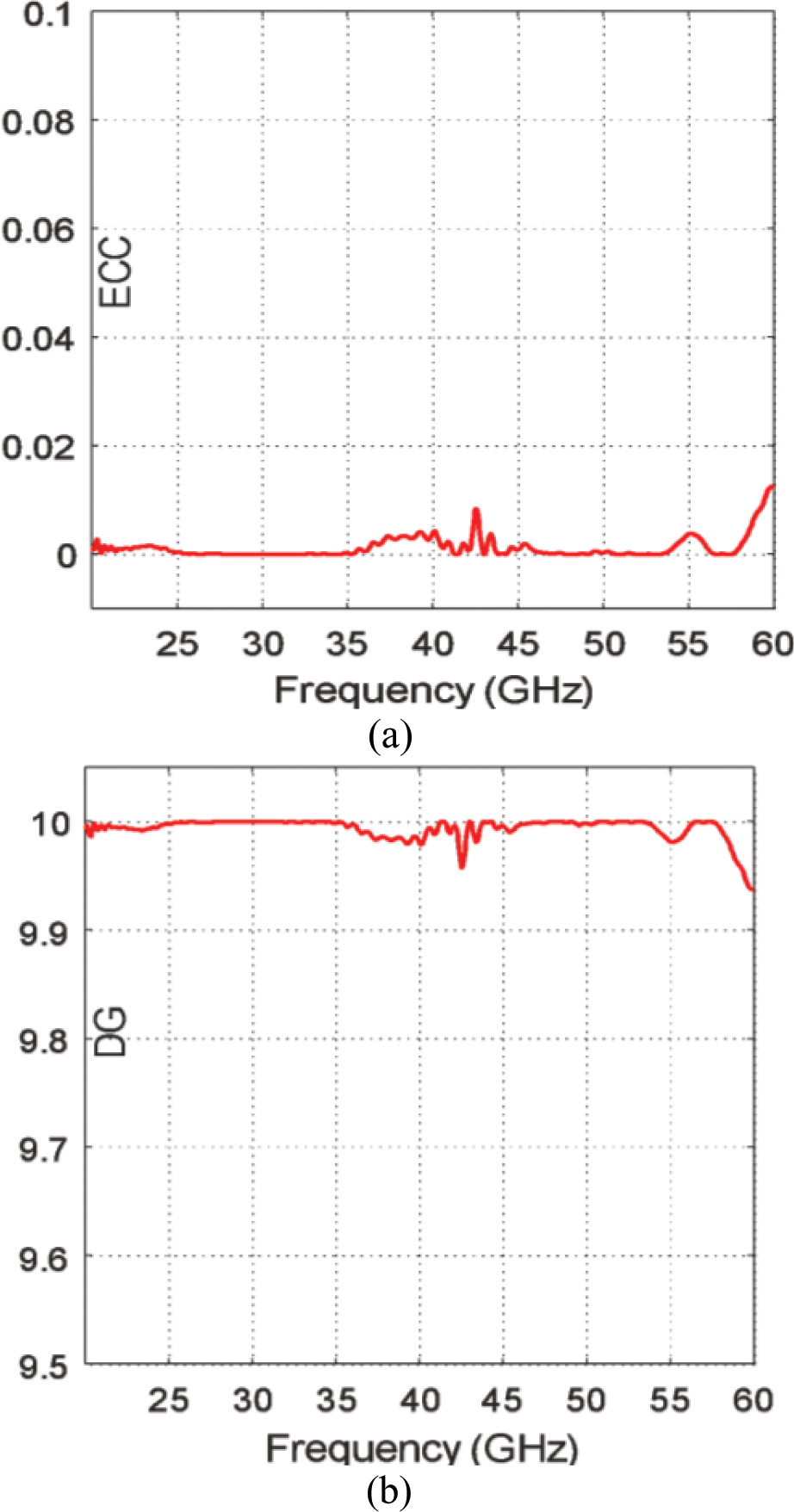
Figure 20: Frequency dependence of the ECC and DG of the cross-polarized two-port MIMO antenna system presented in Fig. 19. (a).
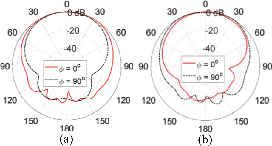
Figure 21: Radiation patterns in the elevation planes for the cross-polarized two-port MIMO antenna system at 28GHz when excited at (a) port and (b) port 2.
B.4. Radiation patterns of cross-polarized two-port MIMO antenna system
The radiation patterns of the total radiated field at the frequencies 28, 43, 52, and 57 GHz are presented in Figs. 20, 21, 22, and 23, respectively in the orthogonal planes and when the cross-polarized two-port MIMO antenna is excited at each port individually. From the radiation patterns in the two orthogonal planes, it can be shown that the cross-polarized two-port MIMO antenna has omnidirectional radiation in the azimuth plane. This makes the antenna a promising candidate for mobile handset applications intended for the forthcoming generation of mobile communications.
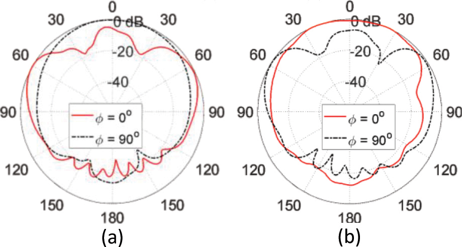
Figure 22: Radiation patterns in the elevation planes for the cross-polarized two-port MIMO antenna system at 43 GHz when excited at (a) port 1 and (b) port 2.
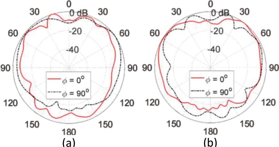
Figure 23: Radiation patterns in the elevation planes for the cross-polarized two-port MIMO antenna system at 52 GHz when excited at (a) port and (b) port 2.
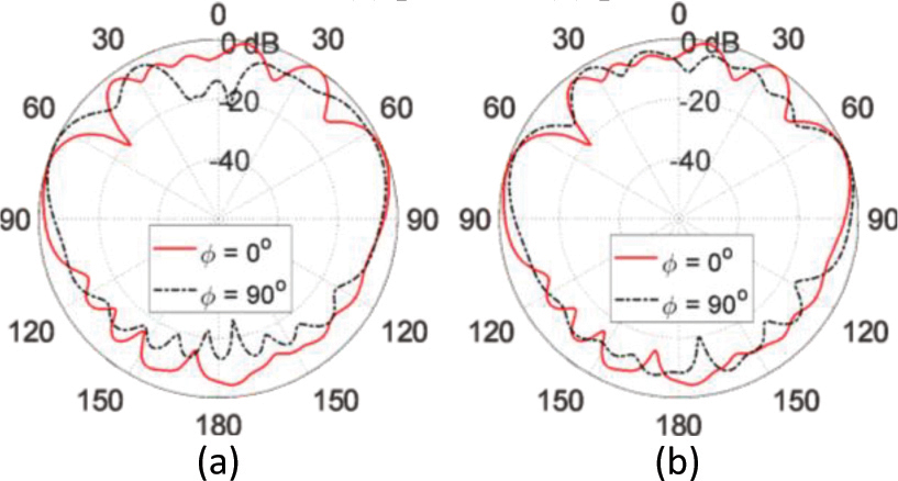
Figure 24: Radiation patterns in the elevation planes for the cross-polarized two-port MIMO antenna system at 57 GHz when excited at (a) port 1 and (b) port 2.
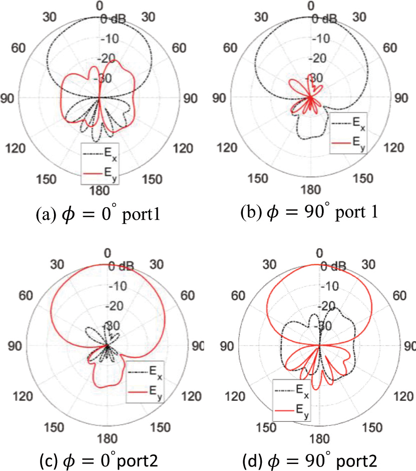
Figure 25: The radiation patterns of the horizontally polarized (-oriented) and vertically polarized (-oriented) electric field radiated from the cross-polarized two-port MIMO antenna system at 28 GHz when the MIMO antenna is excited at each port alone.
For quantitative demonstration of the polarization diversity that can be provided by the cross-polarized two-port MIMO antenna proposed in the present work, the radiation patterns for the -oriented and -oriented components of the far electric field and , respectively, at 28 GHz are plotted as shown in Fig. 24 when the MIMO antenna is excited at each port alone. It is shown that the electric field in the far zone is dominated by vertical (-oriented) component when MIMO antenna is excited at port 1 and is dominated by horizontal (-oriented) component when the MIMO antenna is excited at port 2. Thus, the proposed cross-polarized two-port MIMO antenna provides the polarization diversity required for enhancing the communication system performance.
Table 2: Achieved frequency bands (obtained experimentally) by the proposed quad-band patch antenna and the corresponding gain and radiation efficiency
| Center Frequency (GHz) | Start Frequency (GHz) | End Frequency (GHz) | Bandwidth (GHz) | Gain (dBi) | Radiation Efficiency |
| 7.30 | 86.5% | ||||
| 7.03 | 87.5% | ||||
| 7.20 | 89.2% | ||||
| 8.03 | 90.0% |
4 SUMMARY OF THE PROPOSED MIMO ANTENNA PERFORMANCE
A. Performance of the single-element antenna
A summary of some important performance measures of the proposed single-element antenna used to construct the proposed MIMO antenna systems at the four operational frequencies, is listed in Table 3.
Table 3: Comparison among some millimetric-wave MIMO antennas available in some recent literature and the MIMO antennas proposed in the present work
| Work: | [A01] | [A02] | [A03] | [A04] | [A05] | Present | |
| Number of ports | |||||||
| Polarization | Co-polarized | ||||||
| Cross-polarized | |||||||
| Minimum port isolation ( | |||||||
| Dimensions () | |||||||
| Maximum ECC | NA | ||||||
| Minimum DG | NA | ||||||
| Operational frequencies (GHz) | Band 1 | ||||||
| Band 2 | |||||||
| Band 3 | |||||||
| Band 4 | |||||||
| Bandwidth (GHz) at each frequency | Band 1 | ||||||
| Band 2 | |||||||
| Band 3 | |||||||
| Band 4 | |||||||
| Gain (dBi) at each frequency | Band 1 | ||||||
| Band 2 | |||||||
| Band 3 | |||||||
| Band 4 | |||||||
| Antenna efficiency at each frequency | Band 1 | NA | |||||
| Band 2 | |||||||
| Band 3 | |||||||
| Band 4 |
B. Performance of the MIMO antennas
A comparative performance among some millimetric-wave MIMO antennas designed for mobile handsets that are available in some recent literature and the MIMO antennas proposed in the present work can be achieved by demonstrating the most important performance as listed in Table 2.
5 CONCLUSION
Novel designs for compact-size quad-band two-port MIMO antenna systems are introduced for the forthcoming generations of handsets for mobile communications over four frequency bands centered at 28, 43, 52, and 57 GHz. It is shown that the proposed MIMO antennas are well designed to produce appropriate radiation patterns and good impedance matching in the four frequency bands of operation. Some of the proposed two-port MIMO antennas provide spatial diversity while the other type is cross-polarized and provides polarization diversity. The performance of both the quad-band patch antenna and the MIMO antenna systems are assessed including the return loss at each antenna port and the coupling coefficients between the different ports. It is shown that the simulation results agree with the experimental measurements and both show good performance of all the proposed types of MIMO antennas. The bandwidths achieved at approximately 28, 43, 52, and 57 GHz are 0.6, 0.6, 1.8, and 1.5 GHz, respectively. Also, the radiation efficiencies calculated at the four operational frequencies are 86.5%, 87.5%, 89.2%, and 90.0%, respectively. It is shown that the ECC and the DG are perfect over the four operational frequency bands for all the proposed types of two-port MIMO antenna systems.
REFERENCES
[1] R. Bhatti, J. Choi, and S. Park, “Quad-band MIMO antenna array for portable wireless communications terminals,” IEEE Antennas and Wireless Propagation Letters, vol 8, pp. 129-132, 2009.
[2] H. S. Wong, S. Kibria, M. T. Islam, J. S. Mandeep, and N. Misran, “Quad band handset antenna for LTE MIMO and WLAN application,” International Journal of Antennas and Propagation, 2014.
[3] M. Mishra and R. S. Kshetrimayum, “Compact Quad-band MIMO Antenna Array with Low Mutual Coupling for Mobile Terminal,” In IEEE Region 10 Symposium (TENSYMP), pp. 665-670, June 2019.
[4] C. Rajagopal, N. Noorullakhan, S. B. Suseela, and R. Sankararajan, “Compact modified circular patch quad-band MIMO antenna with high isolation and low correlation,” International Journal of Microwave and Wireless Technologies, vol. 9, no. 3, pp. 581-590, 2017.
[5] C. Şeker, T. Ozturk, and M. Güneşer, “A single band antenna design for future millimeter wave wireless communication at ,” European Journal of Engineering and Formal Sciences, vol. 2, no. 2, pp. 35-39, 2018.
[6] E. M. Eldesouki, K. F. A. Hussein, and A. M. El-Nadi, “Circularly polarized arrays of cavity backed slot antennas for X-band satellite communications,” Progress in Electromagnetics Research, vol. 9, pp. 179-198, 2008.
[7] K. F. A. Hussein, “Conical linear spiral antenna for tracking, telemetry and command of low earth orbit satellites” Progress in Electromagnetics Research, vol. 29, pp. 97-107, 2012.
[8] O. A. Elkady, S. A. Abolkassem, A. H. Elsayed, W. A. Hussein, and K. F. A. Hussein, “Microwave absorbing efficiency of Al matrix composite reinforced with nano-Ni/SiC particles,” Results in Physics, vol. 12, pp. 687-700, 2019.
[9] H. Marzouk, M. I. Ahmed, and A. H. Shaalan, “Novel dual-band 28/38 GHz MIMO antennas for 5G mobile applications,” Progress in Electromagnetics Research C, vol. 93, pp. 103-117, 2019.
[10] M. J. Riaz, A. Sultan, M. Zahid, A. Javed, Y. Amin, and J. Loo, “MIMO antennas for future 5G communications,” In 2020 IEEE 23rd International Multitopic Conference (INMIC), pp. 1-4. IEEE, 2020.
[11] B. Aghoutane, S. Das, M. EL Ghzaoui, B. T. P. Madhav, and H. El Faylali, “A novel dual band high gain 4-port millimeter wave MIMO antenna array for 28/37 GHz 5G applications,” AEU-International Journal of Electronics and Communications, p. 154071, 2021.
[12] S. Katragadda, and P. V. Y. Jayasree, “MIMO antenna miniaturization standards for future 5G,” International Journal of Intelligent Unmanned Systems, vol. 10, no. 1, pp. 159-167, 2022.
[13] W. Ali, S. Das, H. Medkour, and S. Lakrit, “Planar dual-band 27/39 GHz millimeter-wave MIMO antenna for 5G applications,” Microsystem Technologies, vol. 27, no. 1 pp. 283-292, 2021.
[14] D. A. Sehrai, M. Asif, N. Shoaib, M. Ibrar, S. Jan, M. Alibakhshikenari, A. Lalbakhsh, and E. Limiti, “Compact quad-element high-isolation wideband MIMO antenna for mm-wave applications,” Electronics, vol. 10, no. 11, 2021.
[15] M. A. El-Hassan, A. E. Farahat, and K. F. A. Hussein, “Compact-size quad-band patch and MIMO antenna system for 5G mobile handsets,” Progress in Electromagnetics Research C, vol. 112, 2021.
[16] M. A. El-Hassan, A. E. Farahat, and K. F. A. Hussein, “Quad-band MIMO antenna system for 5G mobile handsets,” Applied Computational Electromagnetics Society (ACES) Journal, vol. 36, no. 11, 2021.
[17] A. E. Farahat and K. F. A. Hussein, “Dual-band (28/38 GHz) MIMO antenna system for 5G mobile communications with efficient DoA estimation algorithm in noisy channels,” Applied Computational Electromagnetics Society (ACES) Journal, vol. 36, no. 3, pp. 282-294,2021.
[18] A. E. Farahat and K. F. A. Hussein, “28/38 GHz dual-band Yagi-Uda antenna with corrugated radiator and enhanced reflectors for 5G MIMO antenna systems,” Progress in Electromagnetics Research C, vol. 101, pp. 159-172, 2020.
[19] A. E. Farahat and K. F. A. Hussein, “Dual-band (28/38 GHz) yagi–uda antenna with corrugated radiator and triangular reflectors for 5G mobile phones,” Applied Computational Electromagnetics Society (ACES) Journal, vol. 36, no. 10, pp. 1325-1334, 2021.
BIOGRAPHIES

Asmaa E. Farahat received her B.Sc. and M.Sc. at the Department of Biomedical Engineering, Faculty of Engineering, Cairo University, in 2002 and 2006, respectively. She received her Ph.D. in 2012 from Ain Shams University. She is currently an Associate Professor at the Department of Microwave Engineering of the Electronics Research Institute. She has approximately 16 years of scientific research experience. She has published more than 30 papers in international, regional, and local scientific journals and conferences. She has worked as secondary investigator for 3research projects. Her research interests include antennas, electromagnetic wave propagation, risk assessment of human exposure to microwave radiation, remote sensing systems, and radarsystems.

Khalid F. A. Hussein received his B.Sc., M.Sc., and Ph.D. degrees from the Department of Electronics and Electrical Communications, Faculty of Engineering, Cairo University in 1990, 1995 and 2001, respectively. He is currently as a professor at the Department of Microwave Engineering at the Electronics Research Institute. He has more than 30 years of scientific research experience. He has supervised more than 70 doctoral and master theses. He has published more than 110 papers in international, regional, and local scientific journals and conferences. He has served as Head of Microwave Engineering Department at the Electronics Research Institute for 4years. He has been a member of the Egyptian Space Program (currently the Egyptian Space Agency) for more than 8 years. He designed and implemented several satellite antennas between prototypes and finished products. His research interests include antennas, electromagnetic wave propagation, risk assessment of human exposure to microwave radiation, optical communications, photonics, quantum computing, radar systems, particularly ground penetrating radar (GPR), synthetic aperture radar (SAR), and remote sensing systems.
ACES JOURNAL, Vol. 37, No. 8, 875–885.
doi: 10.13052/2022.ACES.J.370806
© 2022 River Publishers