Wearable Panda-Shaped Textile Antenna with Annular Ring-Defected Ground Structure for Wireless Body Area Networks
T. Annalakshmi and S. Ramesh
1Department of Electronics and Communication Engineering
New Prince Shri Bhavani College of Engineering and Technology, Chennai 600074, Tamil Nadu, India
lakshmishanmu15@gmail.com
2Department of Electronics and Communication Engineering
SRM Valliammai Engineering College, Kattankulathur, Chennai 603203, Tamil Nadu, India
rameshs.ece@valliammai.co.in
Submitted On: March 31, 2022; Accepted On: June 16, 2022
Abstract
This research presents a compact panda-shaped wearable antenna with a defected ground structure (DGS). It is fabricated using a flexible material to work at 2.4-GHz industrial scientific medical (ISM) band, confirming the wireless body area network (WBAN) application requirements. The annular ring DGS and circular and elliptical slots in the patch aid in achieving the operating frequency. Good impedance bandwidth is maintained during on-body and bending analysis. Furthermore, this antenna exhibits a peak gain of 7.3 dB and a minimum specific absorption rate (SAR) of 0.0233 W/kg for 1 g tissue and 1.02 W/kg for 10 g tissue. The investigation shows that an antenna with good robustness, compact, high flexibility, and very low SAR makes it a strong candidate for WBAN applications.
Index Terms: Annular ring DGS, bending analysis, flexible, SAR, slot.
I. INTRODUCTION
In the new millennia, there has been constant technological advancement, specifically in wireless body area network (WBAN) communication. The technology has been used across multiple fields, including military and health care [1]. This significant improvement requires the scientific world to invest time and energy to develop WBAN systems, especially wearable antennas that seamlessly integrate into people’s daily wear. This requirement poses a significant challenge for the scientific community to ensure that the wearable antenna designed is flexible, conducive, compact, light-weight, yet non-abrasive, and, importantly, meets the emission standards put forth by international standard organizations [2]. As the antenna is expected to be used on the human body, the parameters that need to be evaluated are frequency shifting, efficiency degradation, and radiation distortion when used near human tissues, as stringent rules cover are applicable for the SAR [3]. Previous research studies prove that the performance of the wearable antenna is impacted when working near a human subject [4].
Several pieces of research have been proposed so far for wearable application in narrowband. Some of the notable contributions are as follows: in [5], a combination of EBG defected ground structure (DGS) technique was employed. In this work, EBG increases the isolation between the human bodies with an antenna, whereas DGS enhances the bandwidth. The L-shaped inverted element with DGS is proposed for the improvement of the bandwidth and gain [6]. In [7], an asymmetric arc-shaped DGS was utilized to reduce the cross-polarization and enhance the gain. The ground plane is modified with four L-shaped slots to radiate the antenna in dual band [8]. Using floating ground planes, the authors produced low specific absorption rate (SAR) value, reduced backward radiation, and improved gain [9]. Adding the meandering slits on the ground plane and fractal structure achieved size miniaturization and bandwidth improvement [10]. In [11], high gain, wideband, and low SAR were obtained using an array antenna with an EBG structure on the ground plane. In [12], dielectric resonator antenna with slotted ground suppresses the substrate effect, reducing the backward radiation. Based on the analysis, DGS is the best choice for the excellent characteristics of the antenna as it supports miniaturization, improving gain, bandwidth, and suppressing backward radiation. This article introduces a compact panda-shaped flexible textile antenna with annular ring DGS for WBAN applications. The suggested antenna is designed as the right choice for wearable applications due to its compactness, flexibility, excellent characteristics in on-body and bending scenarios with low SAR value, and charming shape. There are four sections in this article. The antenna design topology and DGS technique are demonstrated in Section II. The outcome and analysis of the antenna are enlightened in Section III. The conclusion part is discussed in Section IV.
II. ANTENNA DESIGN
A Antenna topology
An elliptical-shaped patch forms the basic structure of the antenna as the face and it is shown in Figure 1.
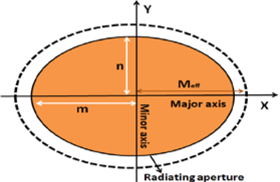
Figure 1: Elliptical structure.
| (1) |
| (2) |
| (3) |
| (4) |
The mathematical analysis of elliptical patch geometry is derived using the approximated Mathieu’s function as depicted in eqn (2.1)–(4) [13–16], where M is the effective semi-major axis, m is the semi-major axis, n is the semi-minor axis, is the dielectric constant of substrate, t is the substrate height, e is the eccentricity of ellipse, f is the resonance frequency, and q is the approximated Mathieu function. Originally, the radiating patch is designed for 2.8 GHz using eqn (2). To improve the S level, gain, and bandwidth, two annular rings are attached as left and right ears on both sides. By increasing the perimeter of the patch bandwidth broadening is achieved [17]. Further, two circle-shaped slots are etched from the face as right and left side eyes. Finally, at the center, an elliptical slot is also etched as a nose. By adding more slots in the patch, more current is interrupted and more energy is radiated from the slot. This boosts the gain and efficiency by increasing the radiated power [18]. This slotted structure forms a panda’s head that attracts people to wear. A feed line is extended from the edge of the face to the bottom of the substrate.
Impact of DGS – on the Antenna Behavior
In the DGS technique, the ground is etched with a defect or slot to improve the antenna’s performance regarding resonance frequency, S, gain, bandwidth, and efficiency [19], [20]. It interrupts the current path of the ground surface and enhances the performance [21]. The shape, size, and position of DGS are calibrated to meet the optimal characteristics. This article introduces a novel idea of annular ring DGS etched on the ground surface. Due to the impact of DGS, resonance frequency shifted from 2.8 to 2.44 GHz with an improved level of S from –22 to –53 dB. Further, it also raises the bandwidth from 40 to 130 MHz. Thus, the overall performance of the antenna is satisfied only with the presence of DGS. The construction of antenna topology is presented in a step-by-step process and is shown in Figure 2. Table 1 shows the detailed measurement of the antenna and the simulation is carried out with CST microwave studio software. The front and back views of the designed antenna are depicted in Figure 3.
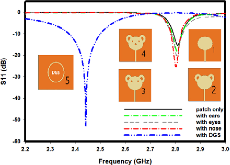
Figure 2: Simulated S for stepwise design.
Table 1: Measurements of the antenna structure
| Parameters | Size in mm |
|---|---|
| Face-X radius | 11.5 |
| Face-Y radius | 8.5 |
| Ear-outer radius (left, right) | 5 |
| Ear-inner radius (left, right) | 2 |
| Nose-X radius | 1.5 |
| Nose-Y radius | 0.5 |
| Eye (left, right) radius | 1 |
| Ground slot – outer radius | 12 |
| Ground slot – inner radius | 11 |
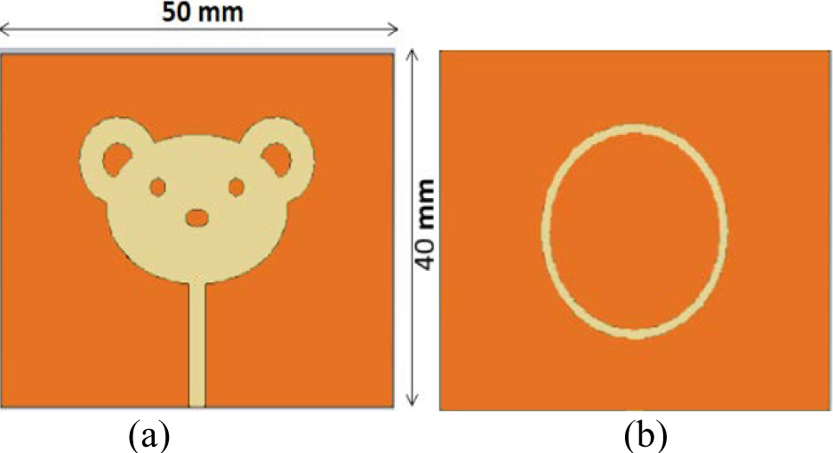
Figure 3: Antenna topology. (a) Front view. (b) Back view.
B Fabricated antenna
The ground structure and patch are fabricated with flexible conductive fabric having 0.05/square surface resistivity. The commonly available jeans cloth is used as a substrate. Its dielectric constant is 1.7, and its thickness is 1 mm [22]. The material is chosen due to its lower dielectric constant value, reducing the surface wave losses and enhancing impedance bandwidth [23]. The substrate thickness is selected as the minimum value of 1 mm to increase the antenna efficiency. The loss tangent value of denim jeans is 0.025. The precise shape of the patch and ground is cut by a laser machine SENFNNG – SF1610. This process provides extreme accuracy and clean cuts and minimizes fraying. The substrate is attached to the patch and ground fabric using fabric glue. A 50 SMA connector is affixed to the feed line for the antenna’s excitation. Figure 4 depicts the antenna prototype in different views.
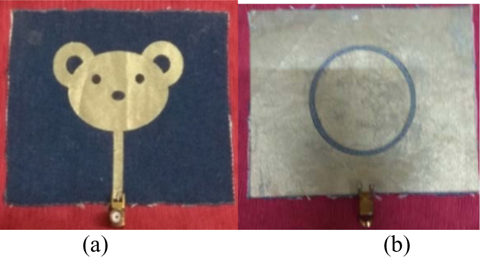
Figure 4: Antenna topology. (a) Front view. (b) Back view.
III. ANTENNA PERFORMANCE
Analysis of the antenna in on-body and free space scenarios was performed to study the standard parameters and SAR and bending analysis. A body phantom with dimension 100 100 13 mm consisting of skin, fat, and muscle is created using a CST microwave studio for on-body simulation. Table 2 lists the physical attributes of each layer [24]. An 8-mm thick jean substrate is implemented between the antenna and body phantom. This creates the real-life scenario of the human wearing clothes. Figure 5 shows the human body phantom and real human models when the antenna is placed.
Table 2: Properties of different tissue
| Properties | Skin | Fat | Muscle |
|---|---|---|---|
| Thickness (mm) | 2 | 3 | 8 |
| Permittivity | 41.3 | 5.3 | 54.8 |
| Density (Kg/) | 1100 | 910 | 1041 |
| Conductivity (S/m) | 0.895 | 0.049 | 0.955 |
The real human body of the female model is used for an on-body measurement. The female model is 41 years old with 154-cm height and 64-Kg weight. The test is performed by placing the antenna on the back of the human model. A gap of 8 mm was maintained between the antenna and the human model. The clothes worn by the human model and the adhesive tape used to fix the antenna on the clothes create a separation of 8 mm.
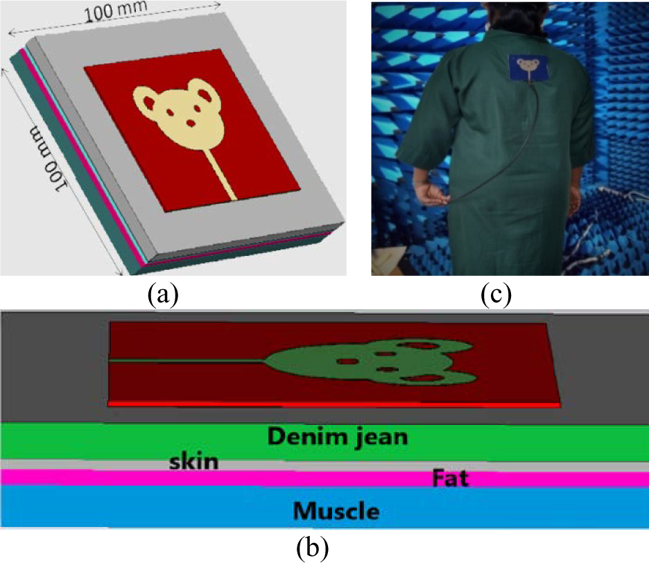
Figure 5: The human body phantom model. (b) Side view. (c) The real model in a chamber.
A Reflection coefficient (S)
The measurement was performed using a vector network analyzer (VNA) with a 0–26 GHz range. The result exhibits good impedance bandwidth covering the industrial scientific medical (ISM) band across 2.40–2.4835 GHz as shown in Figure 6. The S magnitude of the antenna can also be measured by placing the antenna on the body. The dielectric loading effect and conductive nature of the lossy human tissue in close proximity to the worn patch antenna model result in a slight deviation in resonance frequency from 2.45 to 2.47 GHz (20 MHz) and a reduction in S magnitude [25, 26]. Though there is a deviation in resonance frequency, it covers the required impedance bandwidth.
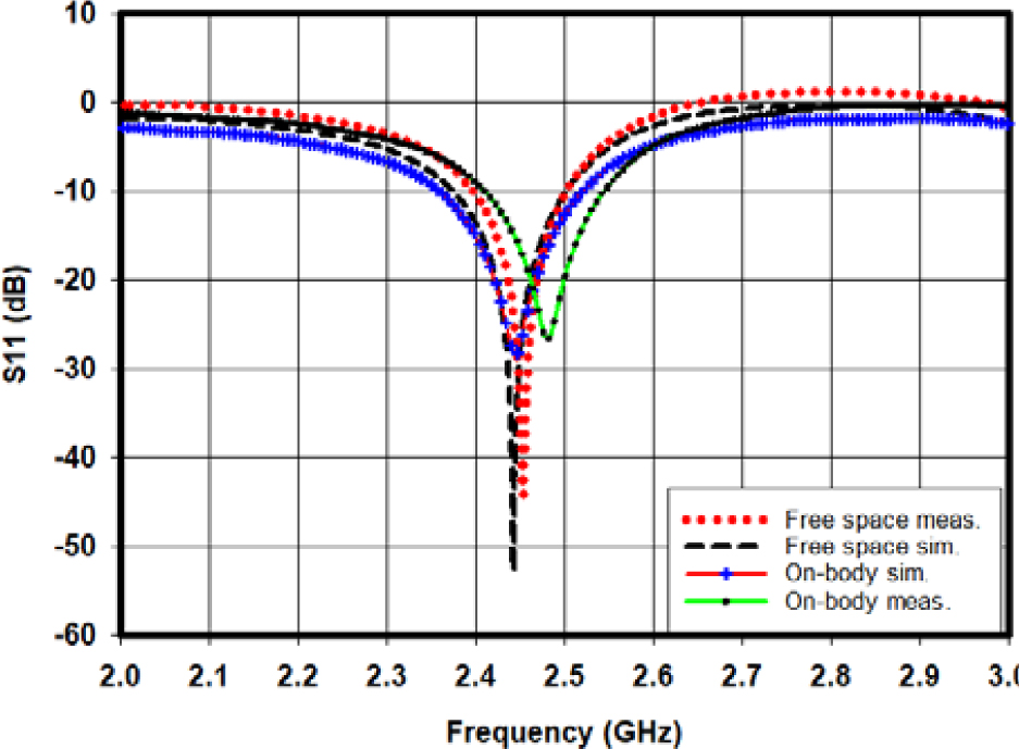
Figure 6: Reflection coefficient (S) response.
B Far-field radiation pattern
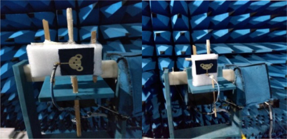
Figure 7: Antenna measurement inside the chamber H-planeE-plane E-plane orientation (left) H-plane orientation (right).
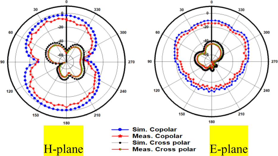
Figure 8: Radiation pattern in on-body scenario.
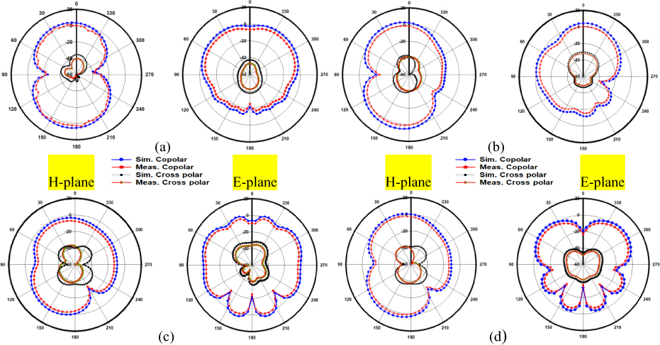
Figure 9: Simulated and measured radiation pattern in free space. (a) Flat antenna. (b) Bending antenna at 80-mm radius. (c) Bending antenna at 60-mm radius. (d) Bending antenna at 40-mm radius.
A shielded anechoic chamber measuring 5.7 3.5 3 m with an operating range of 700 MHz to 18 GHz frequency was used. The photographs of the antenna placement in E-plane and H-plane directions are shown in Figure 7. The observed radiation pattern (co-polar and cross-polar) in both E-plane and H-plane directions for on-body, free space flat, and bending antennas are presented in Figures 8 and 9. In H-plane and E-plane, the antenna produces nearly a bi-directional and omni-directional pattern, respectively, at 2.4 GHz. From the radiation characteristics, it is evident that there is a good isolation between co-polarization and cross-polarization in all scenarios due to the presence of DGS [27]. The radiation patterns are slightly changed when the antenna is bent with higher radius, due to the deformity of the antenna structure. The suggested antenna achieved stable measured radiation performance, which is a good match with the simulation results in on-body, free space flat and bending antennas.
C Bending analysis
The bending analysis was performed to ascertain that the antenna is congruous and robust. The simulation and measurements for different radius curves are predicted in Figures 10 and 11. The bending is done with an 80-, 60-, and 40-mm radius in free space simulation and measurement. The result shows the resonance frequency is being shifted to the left side in the E-plane direction. Contrarily to this, the resonance frequency is shifted to the right side in the H-plane direction. But in both conditions, it nearly covers the required bandwidth. The simulated and measured values are almost the same except for the magnitude of S, as seen in the graph. It may be due to the antenna’s deformity and losses in the fabricated antenna [28].
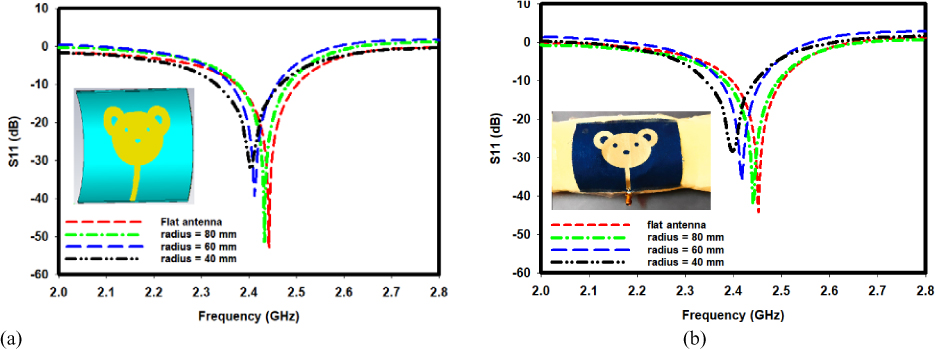
Figure 10: Bending performance at H-plane orientation. (a) Simulated S. (b) Measured S.
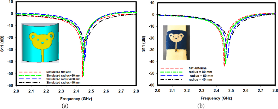
Figure 11: Bending performance at E-plane orientation. (a) Simulated S. (b) Measured S.
D Efficiency and gain response
The efficiency response and gain measurement are illustrated in Figure 12. In a free space environment, the designed antenna achieves a gain of 7.3 dBi in simulation and 5.3 dBi in measurement. The gain variation is due to the losses in the fabricated antenna.
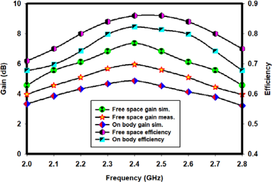
Figure 12: Gain and efficiency response.
There is a further reduction in gain up to 4.8 dBi due to the losses present in the human body. The graph shows that radiation efficiencies in free space are 86% and 82% on a phantom model at 2.4 GHz.
E SAR analysis
SAR is the measure of energy the human body perceives when an antenna is placed on it. Theoretically, SAR can be analyzed through eqn (5), where E is the electric field intensity in V/m, is the conductivity in S/m, and is the mass density in Kg/m [29].
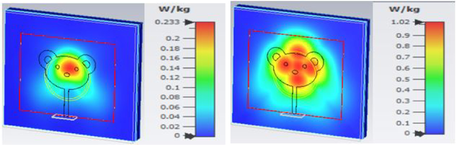
Figure 13: Simulated SAR at 1 g tissue (left-side) and 10 g tissue (right-side).
| (5) |
Table 3: Comparison of DGS antenna with plain ground antenna
| Parameters | Antenna without DGS | Antenna with DGS |
|---|---|---|
| Resonance freq. at | 2.8 GHz | 2.44 GHz |
| Bandwidth | 40 MHz | 130 MHz |
| Gain | 3.8 dB | 7.3 dB |
| Efficiency | 73% | 86% |
Table 4: Comparison of proposed antenna with existing antenna
| References | Size (mm | Substrate material | Patch material | Operating frequency (GHz) | Gain (dBi) | SAR (W/Kg) |
| Ref. [4] | 100 100 | Felt | Nickel–copper–polyester tape | 4.55–13 | 6 | 10 g: 0.107 |
| Ref. [10] | 39 39 |
Roger RT/duroid 5880 |
Copper cladding |
2.4 | 2.06 | 1 g: 0.34 10 g: 0.26 |
| Ref. [24] | 115 123 | Cotton | Zari–silver metallic yarn | 2.4 | 7.11 | 1 g: 0.032 10 g: 0.0115 |
| Ref. [30] | 40 30 |
FR-4 | Copper etching |
2.4/5.8 | 5.08 | 1 g: 0.19 10 g: 1.18 |
| Ref. [31] | 81 81 |
Felt | Nora-Dell-CR fabric |
2.4 | 7.3 | 1 g: 0.554 10 g: 0.23 |
| Ref. [32] | 50 16 |
Jean | Copper tape |
2.4 | 1.98 | 1 g: 0.52 10 g: 0.27 |
| Proposed work | 50 40 |
Jean | Copper fabric |
2.4 | 7.3 | 1 g: 0.233 10 g: 1.02 |
In practical scenario, SAR is calculated by taking an average volume of 1 and 10 g tissue. For 1-g average tissue, the permissible SAR value is 1.6 W/kg as per Federal Communication Commission (FCC) standard. For 10 g tissue, the allowable SAR value is 2 W/kg as per European Standard of the International Electro-Technical Commission (IEC) [30]. The simulated SAR Distribution at frequency 2.4 GHz is shown in Figure 13. Prolonged exposure will result in a high SAR value, which is hazardous to the human body, while the lower value of SAR is desirable as it enhances efficiency. This antenna exhibits a minimum of SAR 0.233 and 1.02 W/Kg for 1 and 10 g tissue, respectively. The value of SAR falls below the standardlimits in both cases, making the antenna suitable for wearable applications.
F Overall comparison in the presence and absence of DGS
Finally, the impact of DGS has been compared with many antenna parameters in the presence and absence of DGS. Table 3 indicates that the antenna with DGS structure has exactly resonated at 2.44 GHz with broader bandwidth and higher gain. It also fulfilled the SAR safety limit with better efficiency. This proves that the presence of DGS is required to achieve the optimal result.
The proposed work has been compared with the results from various literatures in Table 4. The originality of this work is the elegant shape with extreme flexibility in terms of both conductive and substrate materials. The suggested antenna exhibited higher gain (7.3 dBi) in the smaller dimensions structure within SAR safety limits.
IV. CONCLUSION
This research paper proposed a panda-shaped flexible textile antenna that can operate in 2.4 GHz and support WBAN applications. This antenna covers the entire ISM band (2.40–2.4835 GHz). The annular ring DGS was developed to boost antenna bandwidth, gain, and efficiency. In the free space scenario, 7.3 dBi gain is observed at 86% efficiency. On-body condition exhibits 4.8 dBi gain at 82% efficiency. The antenna had good radiation properties with minimal cross-polarization in simulations and measurements. The bending analysis proves that the antenna performs well in E- and H-plane orientations. The value of SAR stays within permissible limits in both 1 and 10 g average tissue. Because of its flexibility and attractive shape, this delightful panda-shaped antenna will blend well with the design of garments. The exhibited features of the proposed antenna make it most appropriate for use in WBAN applications.
ACKNOWLEDGMENT
The authors wish to acknowledge DST-FIST supporting facilities in the Electronics and Communication Engineering Department, SRM Valliammai Engineering College, Chennai, Tamil Nadu, India.
REFERENCES
[1] A. G. Al-Sehemi, A. A. Al-Ghamdi, N. T. Dishovsky, N. T. Atanasov, and G. L. Atanasova, et al., “Flexible and small wearable antenna for wireless body area network applications,” Journal of Electromagnetic Waves and Applications, vol. 31, no. 11-12, pp. 1063-1082, 2017.
[2] A. Kashkool, S. Yahya, H. Al-Rizzo, A. Al-Wahhamy, and A. A. Issac, “On the design and simulation of antennas on ultra-thin flexible substrates,” Applied Computational Electromagnetics Society (ACES) Journal, vol. 33, no. 7, Jul. 2018.
[3] A. Gupta and V. Kumar, “DGS-based wideband MIMO antenna for on–off-body communication with port isolation enhancement operating at 2.45GHz industrial scientific and medical band,” Journal of Electromagnetic Waves and Applications, vol. 35. no. 7, pp. 888-901, 2020.
[4] H. Yalduz, T. E. Tabaru, V. T. Kilic, and M. Turkmen, “Design and analysis of low profile and low SAR full-textile UWB wearable antenna with metamaterial for WBAN applications,” AE International Journal of Electronics and Communications, vol. 126, pp. 1-12, Sep. 2020.
[5] A. Y. I. Ashyap, S. H. Bin Dahlan, Z. Z. Abidin, and M. H. Dahri, et al., “Robust and efficient integrated antenna with EBG-DGS enabled wide bandwidth for wearable medical device applications,” IEEE Access, vol. 8, pp. 56346-56358, 2020.
[6] H. F. Abutarboush, W. Li, and A. Shamim, “Flexible-screen-printed antenna with enhanced bandwidth by employing defected ground structure,” IEEE Antennas and Wireless Propagation Letters, vol. 19, no. 10, pp. 1803-1807, Oct.2020.
[7] C. Kumar and D. Guha, “Asymmetric and compact DGS configuration for circular patch with improved radiations,” IEEE Antennas and Wireless Propagation Letters, vol. 19, no. 2, pp. 355-357, Feb. 2020.
[8] S. Bhattacharjee, S. Maity, S. R. B. Chaudhuri, and M. Mitra, “A compact dual-band dual-polarized omnidirectional antenna for on-body applications,” IEEE Transactions on Antennas and Propagation, vol. 67, no. 8, pp. 5044-5053, Aug. 2019.
[9] C. Wang, L. Zhang, and X. Wu, “A wearable flexible microstrip antenna based on the floating-ground backplane,” International Journal of RF and Microwave Computer-Aided Engineering, vol. 31, no. 1, pp. 1-15, Nov. 2020.
[10] A. Arif, M. Zubair, M. Ali, M. U. Khan, and M. Q. Mehmood, “A compact, low-profile fractal antenna for wearable on-body WBAN applications,” IEEE Antennas and Wireless Propagation Letters, vol. 18, no. 5, pp. 981-985, May 2019.
[11] H. Zu, B. Wu, P. Yang, W. Li, and J. Liu, “Wideband and high-gain wearable antenna array with specific absorption rate suppression,” Electronics, vol. 10, no. 17, pp. 2056, Aug. 2021.
[12] M. Boyuan, J. Pan, E. Wang, and D. Yang, “Wristwatch-style wearable dielectric resonator antennas for applications on limps,” IEEE Access, vol. 8, pp. 59837-59844, 2020.
[13] P. Mythili and A. Das, “Simple approach to determine resonant frequencies of microstrip antennas,” Antennas Propag. IEE Proc. -Microw. vol. 145, no. 2, pp. 159-162, Apr. 1998.
[14] J. V. Jose, A. S. Rekh, and M. J. Jose, “Design techniques for elliptical micro-strip patch antenna and their effects on antenna performance,” International Journal of Innovative Technology and Exploring Engineering, vol. 8, no. 12, pp. 2317-2326, Oct. 2019.
[15] S. Murugan, B. Rohini, P. Muthumari, and M. Padma Priya, “Multi-frequency T-slot loaded elliptical patch antenna for wireless applications,” Applied Computational Electromagnetics Society (ACES) Journal, vol. 1, no. 7, pp. 212-215, Jul. 2016.
[16] A. Agrawal, D. Vakula, and N. V. S. N. Sarma, “Design of elliptical microstrip patch antenna using ANN,” PIERS Proceedings, Suzhou, China, pp. 264-268, 2011.
[17] S. R. Patre and P. Surya Singh, “CPW-fed flower-shaped patch antenna for broadband applications,” Microwave and Optical Technology Letters, vol. 57, no. 12, pp. 2908-2913, 2015.
[18] P. Seyed, “Bandwidth enhancement techniques,” Trends in Research on Microstrip Antennas, edited by Sudipta Chattopadhyay. London: IntechOpen, 2017. DOI: 10.5772/intechopen.70173.
[19] A. Yadav, V. K. Singh, and H. Mohan, “Design of a U-shaped circularly polarized wearable antenna with DGS on a fabric substrate for WLAN and C-band applications,” Journal of Computational Electronics, vol. 18, pp. 1103-1109, May 2019.
[20] M. Haran, G. Dilip Kumar, A. Ferris Garvin, and S. Ramesh, “Hexagonal microstrip patch antenna for early stage skin cancer identification,” International Journal of Telecommunications and Radio Engineering, vol. 79, no. 7, pp. 555-566, Jun. 2020.
[21] B. B. Q. Elias, P. J. Soh, A. A. Al-Hadi, P. Akkaraekthalin, and G. A. E. Vandenbosch, “Bandwidth optimization of a textile PIFA with DGS using characteristic mode analysis,” Sensors, vol. 21, no. 7, pp. 2516, Apr. 2021.
[22] T. Annalakshmi and S. Ramesh, “Performance and analysis of UWB aesthetic pattern textile antenna for WBAN applications,” Applied Computational Electromagnetics Society (ACES) Journal, vol. 35, no. 12, pp. 1525-1531, Dec. 2020.
[23] D. Ram Sandeep, N. Prabakaran, T. P. Madhav Boddapati, and K. L. Narayana, “Circularly polarized jute textile antenna for Wi-MAX, WLAN and ISM band sensing applications,” Applied Computational Electromagnetics Society (ACES) Journal, vol. 35, no. 12, pp. 1493-1499, Dec. 2020.
[24] A. Anbalagan, E. F. Sundarsingh, and V. S. Ramalingam, “Design and experimental evaluation of a novel on-body textile antenna for unicast applications,” Microwave and Optical Technology Letters, vol. 62, pp. 789-799, 2020.
[25] F. S. Esther, M. Kanagasabai, and G. N. M. Alsath, “An investigation of a wearable antenna using human body modeling,” Applied Computational Electromagnetics Society (ACES) Journal, vol. 29, no. 10, pp. 777-783, 2014.
[26] V. Karthik and T. R. Rao, “Performance investigations of a quad-band microstrip antenna for body wearable wireless devices,” Applied Computational Electromagnetics Society (ACES) Journal, vol. 36, no. 08, pp. 980-988, Oct. 2021.
[27] N. RajeshKumar, P. D. Sathya, S. K. A. Rahim, and A. A. Eteng, “Reduced cross-polarization patch antenna with optimized impedance matching using a complimentary split ring resonator and slots as defected ground structure,” Applied Computational Electromagnetics Society (ACES) Journal, vol. 36, no. 6, pp. 718-725, Nov.2021.
[28] S. Varma, S. Sharma, M. John, R. Bharadwaj, A. Dhawan, and S. K. Koul, “Design and performance analysis of compact wearable textile antennas for IoT and body-centric communication applications,” International Journal of Antennas and Propagation, vol. 2021, Article ID 7698765, p. 12, 2021.
[29] S. Singh and S. Verma, “SAR reduction and gain enhancement of compact wideband stub loaded monopole antenna backed with electromagnetic band gap array,” International Journal of RF and Microwave Computer-Aided Engineering, vol. 31, no. 10, pp. 1-11, Jul. 2021.
[30] S. Ahmad, A. Ghaffar, N. Hussain, and N. Kim, “Compact dual-band antenna with paired L-shape slots for on- and off-body wireless communication,” Sensors, vol. 21, no. 23, pp. 7953, Nov. 2021.
[31] G. Gao, B. Hu, S. Wang, and C. Yang, “Wearable circular ring slot antenna with EBG structure for wireless body area network,” IEEE Antennas and Wireless Propagation Letters, vol. 17, no. 3, pp. 434-437, Mar. 2018.
[32] I. Gil and R. Fernandez Garcia, “Wearable PIFA antenna implemented on jean substrate for wireless body area network,” Journal of Electromagnetic Waves and Applications, vol. 31, no. 11-12, pp. 1194-1204, Jul. 2017.
BIOGRAPHIES

T. Annalakshmi received the B.Tech. degree in electronics and communication engineering from Pondicherry University in 2002 and the M.E. degree in communication systems from Anna University in 2011, and is currently working toward the Ph.D. degree with the Department of Electronics and Communication Engineering, SRM Valliammai Engineering College, Chennai, India. Her research interest includes antennas and propagation and wireless communications. She is currently working as an Associate Professor with the
Department of Electronics and Communication Engineering, New Prince Shri Bhavani College of Engineering and Technology, Chennai, India, with 15 years of experience. She is a lifetime member of ISTEand ISRD.

S. Ramesh received the B.E. degree in electronics and communication engineering from the University of Madras, Chennai, India, the M.Tech. degree in communication engineering from VIT University, Vellore, India, and the Ph.D. degree from SRM University, Chennai, India, in 2001, 2004, and 2015, respectively. He is currently working as an Associate Professor with the Department of Electronics and Communication Engineering, SRM Valliammai Engineering College, Chennai, India, with experience of 19.3 years. He is a senior member (S’10-M’17-SM’18) of IEEE Antennas & Propagation Society and Life member in IETE, ISTE, SEMCE, and BES. He authored papers in reputed journals and international/national conferences. His area of research interest includes antennas & propagation and wireless communications. He is guiding research scholars in the field of antennas and RF filter under Anna University, Chennai, India. He is associated with IEEE AP-S Madras chapter as a member in executive committee during 2018–2019 and IEEE MTT-S Madras Chapter for the year 2017.
ACES JOURNAL, Vol. 37, No. 5, 546–553.
doi: 10.13052/2022.ACES.J.370504
© 2021 River Publishers