Design of Compact Multiband MIMO Antenna Based on Ground Neutralization Line Decoupling
Zhonggen Wang1, Weidong Mu1*, Ming Yang2, and Chenlu Li3
1School of Electrical and Information Engineering, Anhui University of Science and Technology, Huainan, 232001, China
zgwang@ahu.edu.cn, mwd18755802702@163.com
2Department of Electrical and Communications Engineering, West Anhui University, Lu’an, 237012, China
myang@ahu.edu.cn
3School Electrical and Information Engineering, Hefei Normal University, Hefei, 230061, China
chenluli@hfnu.edu.cn
Corresponding author: Weidong Mu
Submitted On: April 2, 2022; Accepted On: August 29, 2022
Abstract
A compact, multiband two-port MIMO antenna is proposed in this paper for various wireless transmission networks, where the overall size of the antenna is only 30 20 1.6 mm. The proposed MIMO antenna consists of two radiating patches, each of which comprises a semicircle and a semi-regular hexagon, as well as the surface-etched C-slot and U-slot to tailor the antenna’s return loss characteristics. In proposed antenna, a parasitic branch forms when the ground plane’s meandering branches are symmetrically distributed. On one hand, it can increase the ground plane’s effective area and enhance the antenna’s return loss characteristics. A neutralization line, on the other hand, is generated, thereby limiting the current transmission on the ground plane. A cross-shaped slit in the ground’s center is also employed to further promote isolation between the radiation elements. According to obtained results, the antenna can cover the frequency bands 0.67-7.29 GHz, 8.07-12.11 GHz, 14.07-15.41 GHz, and 16.04-22 GHz (S1110 dB). Moreover, an RF isolation larger than 18 dB exists between the two ports. Lastly, in terms of ECC, DG, TARC, CCL, and MEG, the diversity performances are all satisfactory.
Index Terms: Decoupling, diversity performance, MIMO antenna system, multiband.
I. INTRODUCTION
Multiple-input multiple-output (MIMO) technology is becoming increasingly popular in wireless transmission terminals and systems, owing to its high speed and scalability [1]. The MIMO antenna system is used in the wireless transmission systems to meet the demands of increased system capacity, reduced latency, improved resilience, and restricted area [2]. Furthermore, miniaturized MIMO antenna systems are now being developed to reduce the size and cost, and improve portability. In view of this, the realization of appropriate and well-specified MIMO antenna designs is a major challenge for current wireless systems [3]. If the MIMO antenna functions only in a single restricted frequency band, the MIMO antenna in that frequency band will not be able to fully utilize the antenna’s inherent benefits and will squander the frequency band resources. Therefore, designing an antenna for wireless applications that can encompass dual-band or multi-band while maintaining a sufficient amount of performance is one of the key technical issues encountered by current wireless terminals and systems.
Due to a demand for multiple frequency bands, various strategies have been utilized in literature to design dual-band or multi-band antennas. A novel metamaterial based antenna etched with a spiral-shaped structure to behave as a complimentary split ring resonator (CSRR) antenna is presented in [4]. The optimized antenna can cover three bands: 1.9 GHz (1.78-1.91 GHz), 2.45 GHz (2.23-2.52 GHz), and 3.2GHz (2.9-3.25 GHz). In [5], a 4-shaped, two-element MIMO antenna system that can cover the bands 0.803-0.823 GHz and 2.44-2.9 GHz of LTE wireless standard were designed. Likewise, in [6], a compact monopole antenna with a pentagon-shaped patch, symmetrical hook-shaped resonators, and one vertical slot was reported, which was claimed to operate at three frequencies: 3.5 GHz, 5.4 GHz, and 8 GHz. In addition, a defected ground plane-based planar antenna operating at frequencies of 2.47 GHz, 3.55 GHz, and 5.55 GHz for Wi-Fi/WiMAX/WLAN applications was presented in [7]. Utilizing a new coplanar waveguide (CPW) with two slots reported in [8], the lower band operating at 2.453-2.821 GHz, and the higher band running at 5.876-6.892 GHz, might be created. To minimize the size of MIMO antennas while maintaining electrical performance, [9] employed a unique iterative approach based on Koch curves and Sierpinski square-slot fractals for rectangular patches. By combining fractal structure and CPW feed technology, the hybrid MIMO antenna provides dual-band coverage (1.81-3.17 GHz). Furthermore, a unique and compact planar MIMO antenna composed of a collapsed monopole and an inclined rectangular metal patch was reported in [10] for several frequencies such as GSM 900 MHz, DCS 1800 MHz, LTE-E 2300 MHz, and LTE-D 2600 MHz. The WLAN MIMO antenna system, operating in the frequency ranges of 2.4–2.48 GHz and 5.15-5.825 GHz and consisting of a dual frequency monopole structure and a curved decoupling resonator coupled to the ground, was first described in [11]. Similarly, the monopole structure was also utilized in [12], where each antenna covered the 2.45 GHz and 5.25-5.775 GHz frequency bands using double-folded monopoles for wireless communication. Progressively, for WLAN/WiMAX/Wi-Fi/4G-LTE and 5G bands, a four-element dual-band MIMO design containing inverted-L monopole antenna modules loaded by a split-ring resonator (SRR) was developed in [13]. In [14], a CPW-fed MIMO antenna was reported with an inverted U-shape and meandering line slots that increased the bandwidth performance. The antenna was observed to be advantageous for Bluetooth, WLAN, and WiMAX applications. A microstrip patch antenna in the form of a hexagon that can operate in three frequency bands was shown in [15]. By applying two inclined strips and cutting modified slots on the radiating patch, the antenna’s multiband functionality was improved, allowing it to be tailored for WLAN, TV satellite broadcasting, WiMAX (5.25-5.85 GHz), IEEE 802.11a (5.47-5.725 GHz), 5G Unlicensed band (5.2-5.7 GHz), weather monitoring, and radar applications, where the antenna operated at three frequencies of 5.40 GHz, 6.76 GHz, and 8.82 GHz. In addition, as shown in [16], the characteristic mode theory (TCM) was used to create multifrequency antennas. When one of three identical square monopoles was excited using TCM, the other two monopoles were viewed as parasitic elements, lowering the monopole’s Q factor and increasing the antenna’s bandwidth. The high-order loops of the metal were activated and new resonance spots were created by adding metal patches to parasitic components, and then metal strips were added to the metal ring for low-frequency bandwidth. However, the MIMO antenna systems mentioned above have drawbacks such as a limited frequency range, large size, or complicated structure, and there is still potential for improvement in antenna operating frequency, size, and structure.
However, on the other hand, mutual coupling between the antenna elements is severe in compact MIMO systems, due to a small distance between the radiation patches, thus affecting the diversity performance. Hence, the key to maintaining the MIMO system’s performance is to reduce the mutual coupling between the radiating elements. The electromagnetic coupling effects have been addressed using a variety of methods in an integrated antenna system. Various decoupling measures have been investigated and applied in the literature including defected ground structure (DGS) [17–19], orthogonal polarization [20], electromagnetic band gap (EBG) [21, 22], neutralization line [23, 24], meander lines [25], and artificial resonators [26–29]. These decoupling techniques provide valuable guidance in the design of MIMO antenna systems.
Above all, the goal of this work is to develop a unique multiband two-port MIMO antenna with a simple structure for wireless communication, which can achieve multi-frequency coverage (0.67-7.29 GHz, 8.07-12.11 GHz, 14.07-15.41 GHz, and 16.04-22 GHz). The proposed antenna is 30 20 1.6 mm in size, and the isolation between its radiating elements is improved by the proposed ground branch and cross-shaped slot. The proposed antenna has four operational bands that may essentially be used to support various communication networks. In addition, diversity characteristics are also good. It should be stated here that this work aims to develop an antenna template for a new generation of ground early warning radar for a research institute in East China. Its basic requirements are small size, can cover 5G, X, and Ku bands, and can achieve linear polarization.
II. ANTENNA DESIGN
A. Geometry of the proposed antenna
The structure of the proposed compact and multiband two-port MIMO antenna with a defected ground plane is presented in Fig. 1. The proposed antenna has an overall size of 30 20 1.6 mm and was designed on FR4 substrate with 1.6mm thickness (tan = 0.02 and = 4.4). It contains two identical modified radiating elements and a defected ground plane. A single radiating element excited by a microstrip line is composed of a semicircle and a semi-regular hexagon, where C-shaped and U-shaped slots are etched perpendicularly on its surface to ameliorate the impedance matching performance and the bandwidth. By introducing meandering ground branch and etching two symmetrical rectangular slots and a cross-shaped slot, the ground structure of this article is presented. In this design, the purpose of meandering ground branch is two-fold. On one hand, it acts as a part of the antenna element to change and improve the return loss characteristics. While on the other hand, it is used as a neutralization line to improve the isolation between two ports. An additional etched cross-shaped slot is put in the center of ground plane to minimize the mutual coupling based on neutralization line even further, without affecting the elements’ reflection coefficient performances. Table 1 lists the optimum parameter dimensions of the proposed two-port MIMO antenna.
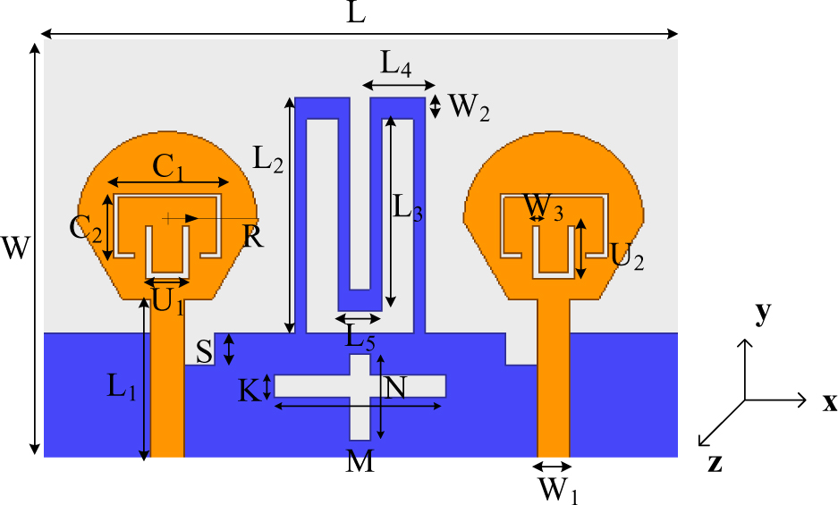
Figure 1: Geometrical structure of the proposed two-port MIMO antenna.
Table 1: Optimized parametric dimensions of proposed MIMO antenna (unit: mm)
| L | W | L | L | L | L |
|---|---|---|---|---|---|
| 30 | 20 | 7.56 | 11 | 10 | 2.5 |
| L | C | C | C | R | W |
| 2 | 5 | 3 | 1.15 | 4.2 | 1 |
| U | U | M | N | K | S |
| 2 | 2.5 | 8 | 4 | 1 | 1.5 |
B. Design evolution stages of the single antenna
Initially, a planar monopole antenna with a wide frequency range was used in the design of a single radiating element, to ensure a wideband design. Fundamentally, the circular or regular hexagonal radiating patch has greater wideband properties, as highlighted in literature [30, 31]. Accordingly, this design combines a semicircle and a semi-regular hexagon to construct the fundamental radiation element based on the above. The radius has been calculated by following Equation (1)and (2) [32].
| (1) |
| (2) |
Since the fundamental radiating element can only exhibit broadband characteristics within a specific frequency range and cannot provide multi-frequency coverage, the shape of antenna patch must be altered. To target several frequencies and improve the antenna’s impedance matching qualities, it is beneficial to etch a C-shaped slot on its surface. The slit acts as a quarter-wavelength resonator, the length of C-shaped slot and resonant frequency can be calculated as
| (3) |
| (4) |
where Ls is the total length of the C-shaped slot, fs is the first resonant frequency, is half of the dielectric constant of the FR4, due to the lack of ground, c is the speed of light. The length of Ls is 13.3 mm and the resonant frequency fs is at 3.8 GHz by calculating.
Next, the 50 transmission line feed is used in conjunction with the fractional ground plane to investigate the effects of alternative single antenna structures. The steps in the design of a single antenna element of the proposed MIMO antenna system are depicted in Fig. 2, whereas the operating principle of the antenna element is explained using its reflection coefficient characteristics curves in Fig. 3.
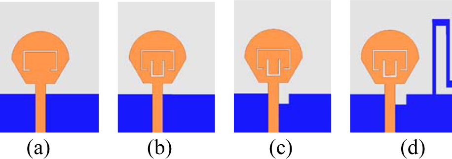
Figure 2: Evolution of the design process of single element: (a) Step-1, (b) Step-2, (c) Step-3, (d) Step-4 (proposed single element).
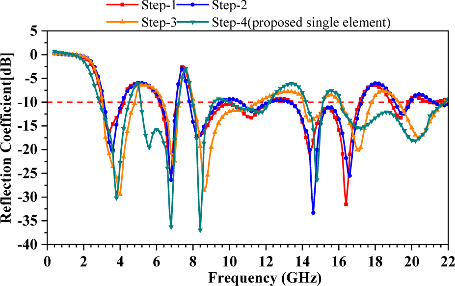
Figure 3: Comparison of reflection coefficient of 4 designs of a single element of the proposed antenna.
It can be observed from Fig. 3 that the antenna designed in Step-1 (including a C-shaped slit and a complete ground) exhibits seven resonating frequency points i.e., 3.5, 6.9, 8.5, 11.3, 14.5, 16.5 and 19.5 GHz with impedance available bandwidths of 1.1 GHz, 1.0 GHz, 4.0 GHz, 3.6 GHz and 0.8 GHz, respectively. And after comparison, when the C-shaped slit is only etched, the first resonance frequency generated is close to the result calculated by Equation (4).
Furthermore, as illustrated in Step-2 of Fig. 2, introducing a U-shaped slot under the C-shaped slit in the single antenna patch allows the antenna to resonate at eight different frequencies. The length of U-shaped slot and resonant frequency can also be calculated as
| (5) |
| (6) |
From the result of Fig. 3, the second resonant frequency is around 6.8 GHz, which is similar to the calculation value of 7.1 GHz, indicating etched U-shaped slot acting as a quarter-wavelength resonator in step-2. In particular, 21.8 GHz is added to the resonance points compared to the design in Step-1, where the common resonance points are just slightly changed. It is worth noticing that the antenna’s reflection coefficient decreases at low frequencies, indicating an improvement in impedance matching performance. Essentially, the reflection coefficient is reduced by 3.85 dB at 3.6 GHz, and 5.05 dB at 8.2 GHz. However, since the reflection coefficient data from Step-1 and 2 show that just changing the antenna shape (etching C and U-shaped slots) does not provide enough bandwidth at low frequencies (particularly at 3-5 GHz), the next step in the design process is to investigate the modification of ground plane geometry.
A defective monopole ground plane with a rectangular slit is proposed in the following design, as highlighted in Fig. 2. In comparison to the design of Step-2, this geometry possesses two less frequency bands and resonates at six different frequencies (4.0, 7.0, 8.6, 14.4, 17.0, and 20.4 GHz). In addition, the antenna element’s impedance bandwidth in the low-frequency band is increased compared Step-1 to Step 2, reaching 1.80 GHz (3.1-4.9 GHz) and 3.4 GHz (8.1-11.5 GHz), thereby covering additional 5G bands and X-band. Certainly, alterations to the ground plane structure have caused these changes. Based on the foregoing explanation, it is reasonable to expect that any further advancements in the ground plane structure will allow the antenna components to have lower frequency bands with enhanced bandwidths.
Correspondingly, a new antenna design (Step-4) was created to improve the performance by applying a meandering ground branch in the fractional ground plane as shown in Fig. 2 (d). The branch functions as a resonator to obtain an extra resonance mode. The resonant frequency can be calculated as:
| (7) |
| (8) |
The calculated length of L is 24.5 mm and the resonant frequency is at 5.8 GHz. The corresponding reflection coefficient curve can be seen in Fig. 3. From Fig. 3, the antenna developed in Step-4 indeed aids in the addition of a 5.6 GHz (closed to calculated value) frequency band (5.15-7.22 GHz) to the existing six frequency bands. When compared to the design of Step-3, the lower frequency in this design is moved to the left, where the equivalent impedance bandwidth is 1.63 GHz (2.87-4.50 GHz). Essentially, the meandering branch increases the ground’s effective area, improves the antenna’s impedance matching performance, and effectively saves space, thereby allowing the integration of multiple similar antennas in a small space to create an innate condition and allowing the antenna design to progress towards miniaturization. Owing to improved parameters in terms of impedance characteristics i.e., increased number of resonating frequencies and enhanced impedance bandwidths, it is noticeable from the findings that the antenna structure created in Step 4 can be used as the final geometry of a single element of the proposed two-port MIMO antenna.
C. Influences of ground plane on two-port MIMOantenna
A single antenna element is transformed into a MIMO system to achieve effective diversity characteristics and high isolation, thereby allowing the proposed wireless device to boost data throughput. The distance, relative location, and other parameters between multiple elements are addressed during the design of the overall MIMO system. Finally, the meandering ground branches are joined to form the original ground geometry structure using a two-port antenna system. The goal here is to minimize the antenna size, and the linked stubs in the MIMO system create a neutralization line that may be utilized to increase the isolation. Besides, the geometry of the ground plane has been adjusted based on the structure of the neutralization line to improve the antenna’s impedance matching performance and the isolation between the antenna components. Fig. 4 demonstrates the evolution phases of the ground plane for the proposed MIMO antenna system. Likewise, Fig. 5 and 6 plot the reflection coefficient (S11) and transmission coefficient (S12) determined from the simulations.
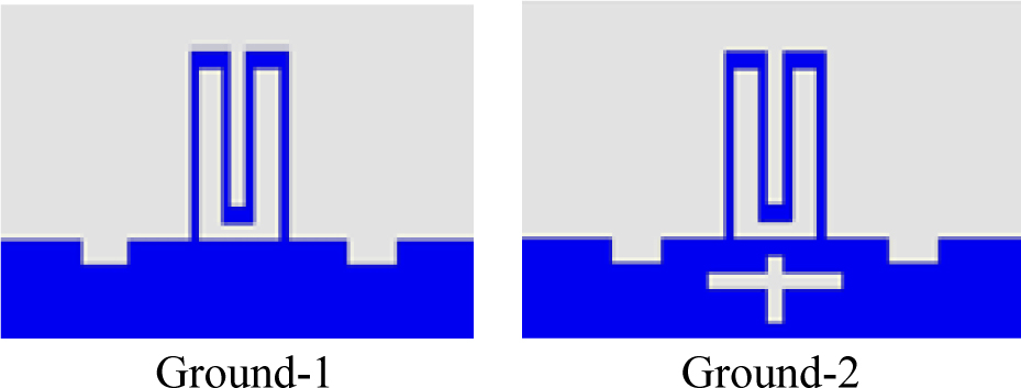
Figure 4: Evolution stages of the ground plane.
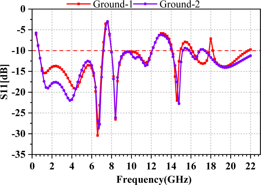
Figure 5: S11 parameter of MIMO antenna for different structure of ground plane.
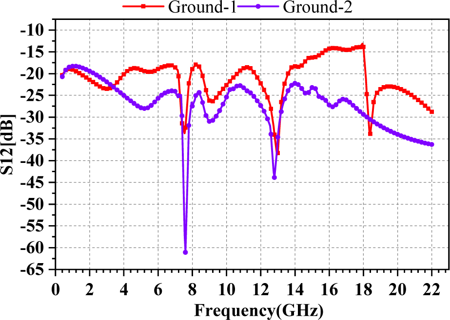
Figure 6: S12 parameter of MIMO antenna for different structure of ground plane.
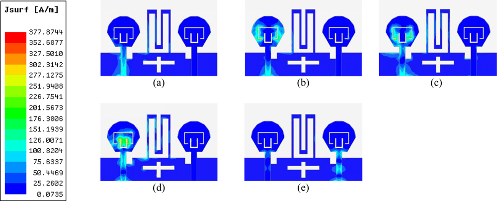
Figure 7: Surface current distribution only when port1 is excited at (a) 3.8 GHz, (b) 6.8 GHz, (c) 8.4 GHz, (d) 15 GHz, (e) 19.4 GHz.
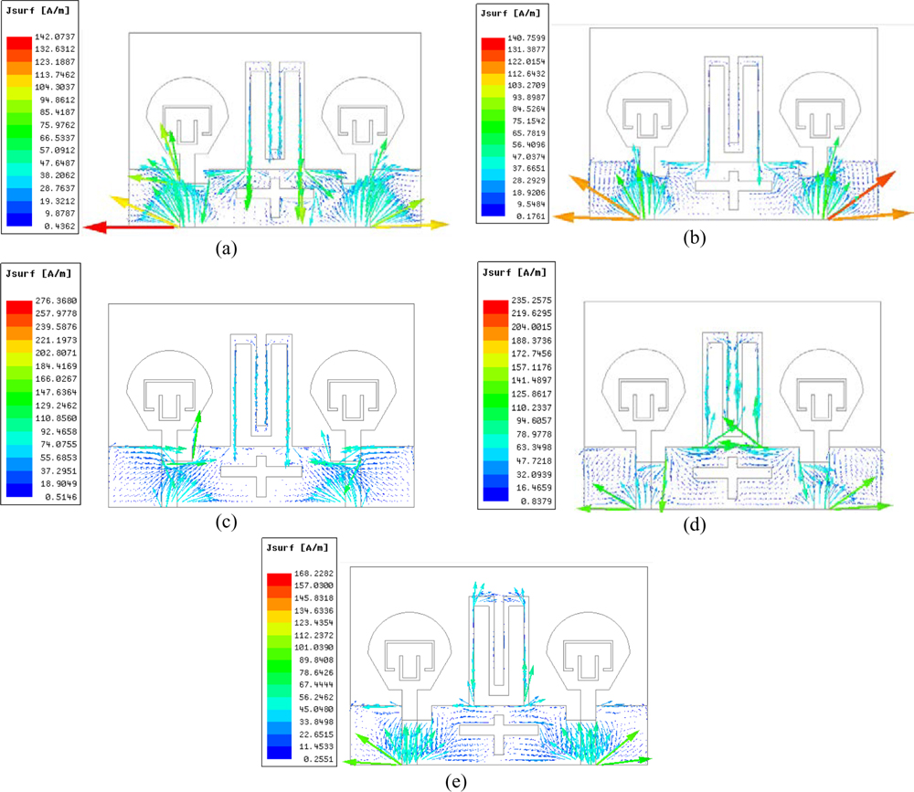
Figure 8: Vector current distribution of ground plane at (a) 3.8 GHz, (b) 6.8 GHz, (c) 8.4 GHz, (d) 15 GHz, (e) 19.4 GHz.
Evidently, the integrated MIMO system exhibits enhanced impedance bandwidth as compared to a single antenna. At sub-7 GHz, the single antenna has two bands (2.86-4.49 GHz and 5.12-6.88 GHz), whereas the MIMO antenna combines the two bands into one wider band (0.68-7.13 GHz). Similarly, in the X-band, MIMO antenna has a broader bandwidth of 7.98-12.09 GHz, although there is no significant difference at higher frequencies. The frequencies covered by the MIMO antenna with Ground-1 are 0.68-7.13 GHz, 7.98-12.09 GHz, 14.13-14.97 GHz, 16.14-17.83 GHz, and 18.20-21.79 GHz (for S1110 dB). In the frequency ranges of 0.68-7.13 GHz and 7.98-12.09 GHz, the mutual coupling (S12) is less than 18 dB. Similarly, S12 is less than 16 dB, 13dB, and 23dB in the frequency range of 14.13-14.97 GHz, 16.14-17.83 GHz, and 18.20-21.79 GHz, respectively. That is to say, MIMO antenna has remarkable decoupling properties.
Next, a cross-shaped slot is inserted in the middle of the ground plane structure of Ground-1 to realize the geometry of Ground-2. To further minimize the mutual coupling between the two antennas, as shown in Fig. 4. The reflection coefficient at lower frequencies is noticeably lowered after using Ground-2, showing a further improvement in the impedance matching ability. Particularly, the S11 is 19.1dB at 1.52 GHz and 22.4dB at 3.80 GHz, which is significantly better than the characteristics of Ground-1. Meanwhile, the higher frequency of 17.22 GHz is moved to the left to 16.38 GHz, without having a significant impact on the high-frequency coverage. Aside from that, the reflection coefficient for 8-12 GHz frequency band is scarcely changed in any situation. To put it another way, the addition of a cross-shaped slot has little impact on the original frequency range. The mutual coupling, on the other hand, has improved substantially. That is to say, the proposed MIMO antenna has eight resonant frequency points at 1.52, 3.80, 6.80, 8.40, 11.37, 15.00, 16.38, and 19.40 GHz, with mutual coupling (S12) values of 18.6, 24.3, 23.9, 24, 23.2, 27.1, and 32.8 dB. The S12 achieves the lowest value of 60.1dB at 7.60 GHz. The cross-shaped slot effectively removes the coupling effect without changing the frequency band, as illustrated in Fig. 6. It is reasonable to assume that the ground plane plays a critical role in enhancing the proposed MIMO antenna’s performance characteristics in terms of impedance matching and isolation. Ground-2 has a simpler structure and great practicability as compared to other reported decoupling structures, making the antenna structure, making the antenna structure more compact.
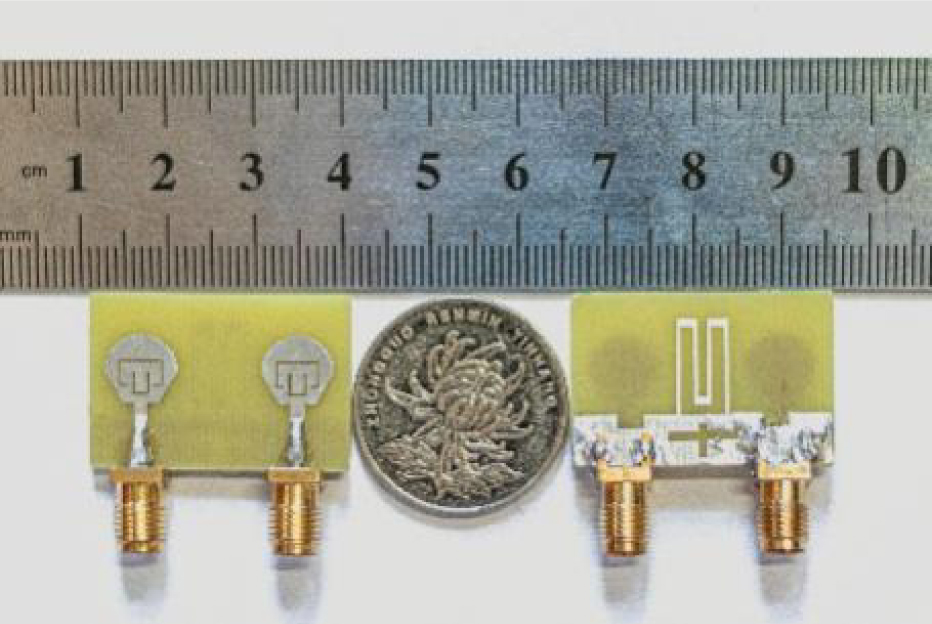
Figure 9: Fabricated prototype of proposed two-port MIMO antenna.
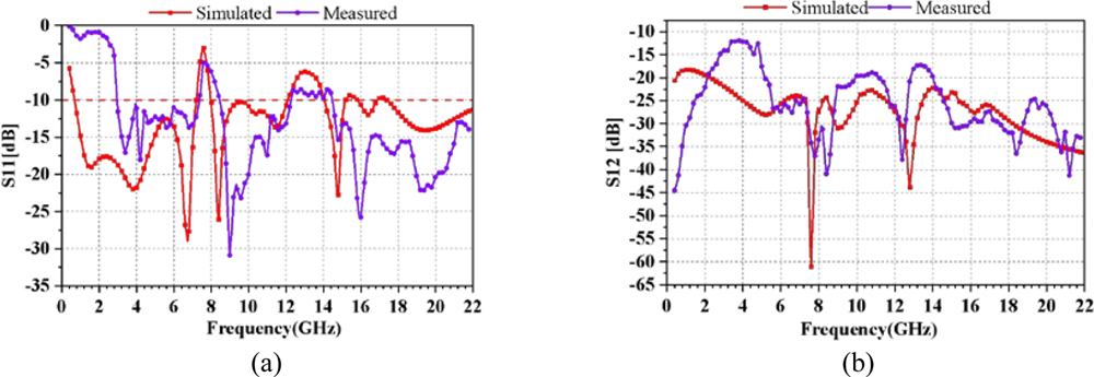
Figure 10: The results of simulated and measured S-parameters of (a) S11, (b) S12.
D. Current distribution
The surface current distribution in the prominent resonance modes is shown in Fig. 7, to visually highlight the decoupling impact of the adopted ground plane geometry. Port-1 is excited in the MIMO system, whereas port-2 is terminated with a matching load of . When just port-1 is excited, the majority of the current is dispersed on the radiating element-1, and there is almost no current distribution on the surface of radiating element-2. The current distribution characteristics of the ground when the two ports are excited simultaneously are simulated, and the vector current distribution of the ground plane in the resonance modes is shown in Fig. 8, to further demonstrate the working mechanism of the ground decoupling structure. From Fig. 8, near-identical currents in opposite directions cancel out at the meandering ground branch in major resonance modes, reducing part of the current interference provided by the ground. The meandering ground branch offsets the current to some degree and acts as a neutralization line in this operation. Moreover, the etched cross-shaped slot, on the other hand, efficiently limits or prolongs the ground’s current transmission, enhancing the decoupling effect even more. According to the findings, the meandering ground branch-based double decoupling structure would effectively improve isolation.
III. RESULTS AND DISCUSSIONS
Figure 9 shows the fabricated prototype of the proposed antenna, which is excited by a 50 coaxial cable. An Agilent N5247A vector network analyzer was used for testing the S-parameters. During the measurement process, the selected sweep frequency range for the measurement method is 0.4-22 GHz, the intermediate frequency bandwidth (IFBW) is 100 kHz, and the number of frequency points is 201. The results are presented and explained in the sections that follow.
A. S-parameter
The results of simulated and measured S-parameters are compared in Fig. 10. It can be observed from Fig. 10 (a) that the operative bands of the measured reflection coefficients (S11-10 dB) encompass 2.9-7.3 GHz, 8.48-12.3 GHz, 14.5-22 GHz. It is worth emphasizing that the discrepancy between the measured and the simulated result mainly exists below 5 GHz, which may be due to fabrication flaws such as changes in physical dimensions of the fabricated prototype, soldering process, environmental conditions, and so on, but it has hardly affected on its operating bandwidth characteristics. In terms of isolation, as evident from Fig. 10 (b), the measured isolation of the proposed MIMO antenna has a minimum value of 44 dB. Moreover, the transmission coefficient is below 12 dB at the operative bands, indicating a good decoupling effect.
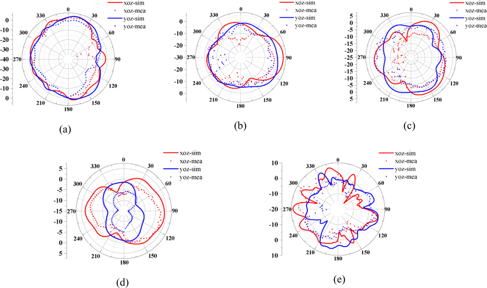
Figure 11: The simulated and measured radiation patterns of port-2 at (a) 3.8 GHz, (b) 6.8 GHz, (c) 8.4 GHz, (d) 15 GHz, (e) 19.4 GHz.
B. Radiation characteristics
The measurements of the radiation patterns were carried out in an anechoic chamber and the selected IF bandwidth of the NSI antenna system for measuring radiation patterns was 1 kHz. The simulated and measured radiation patterns at five resonance frequencies demonstrating the antenna’s xoz and yoz-plane are delineated in Fig. 11. The radiation patterns of both radiating elements are almost similar since the two antennas are symmetrically placed and virtually indistinguishable. Therefore, only the radiation patterns at port-2 are analyzed. As seen in Fig. 11, the radiation pattern is skewed at lower frequencies and practically omnidirectional at higher frequencies. The highest radiation at low frequencies (3.8, 6.8, and 8.4 GHz) is largely spread at roughly 90 in both xoz- and yoz-planes, thereby showing that the antenna is linearly polarized. The direction of the major lobe of the xoz-plane is 90 and 270 at 15 GHz, while that of the yoz-plane is 0 and 180, implying that the electromagnetic wave propagates vertically on these two surfaces. At 19.4 GHz, the radiation pattern improves and spreads more widely. Essentially, it can be assumed that the antenna possesses a strong radiation performance, and can transmit and receive signals well in various wireless networks.
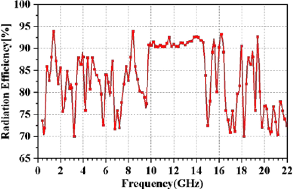
Figure 12: The radiation efficiency of the proposed two-port MIMO antenna.
Figures 12 and 13 demonstrate the radiation efficiency and peak gain of the proposed two-port MIMO antenna. The numbers for just one radiator are provided here since the proposed MIMO antenna’s radiators are symmetrical in design. Radiation efficiency ranges between 70 and 93 percent, indicating that the bulk of the energy is radiated away. At 7.6 GHz, the single antenna achieves a maximum gain of 6.2 dBi. The proposed MIMO antenna has a positive gain value ranging from 3.37 to 6.2 dBi over the whole operating frequency range. Based on the foregoing findings, the proposed two-port MIMO antenna system has good radiation characteristics.
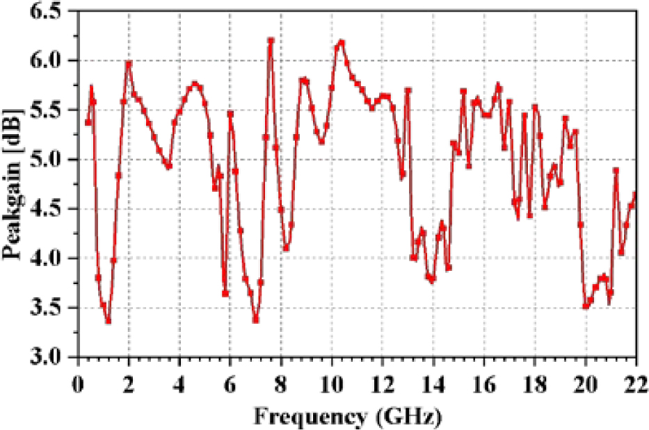
Figure 13: The peakgain of the proposed two-port MIMO antenna.
IV. DIVERSITY PERFORMANCE
The MIMO antenna’s excellent diversity features provide an improved anti-fading and anti-interference performance, allowing each antenna to operate independently. This section will detail and examine the proposed MIMO antenna’s diversity performance in terms of envelope correlation coefficient (ECC), diversity gain (DG), total active reflection coefficient (TARC), channel capacity loss (CCL), and mean effective gain (MEG).
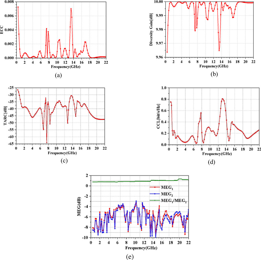
Figure 14: The calculated diversity performance parameters of (a) ECC, (b) DG, (c) TARC, (d) CCL, (e) MEG.
A. Envelope correlation coefficient (ECC)
The ECC value is a key metric for assessing the radiation pattern’s performance, among MIMO radiators. Fundamentally, the ECC is zero if the polarization orientations of the two antennas are perpendicular to each other. When acting alone, the smaller the value of ECC, the less the antennas are impacted by each other. The specified ECC value of a MIMO system in wireless communication networks is normally less than 0.5, to ensure the effective operation of each antenna [33]. The formula for calculating the ECC is given as [34]:
| (9) |
Accordingly, the ECC values computed for the proposed MIMO antenna are displayed in Fig. 14 (a). From Fig. 14 (a), the ECC values are less than 0.008, thereby indicating a satisfactory degree of diversity performance.
Table 2: Performance comparison of proposed two-port MIMO antenna with other works
| Reference | Size(mm) | Bandwidth (GHz) | Isolation (dB) | ECC | TARC(dB) | CCL(bits/s/Hz) | Peakgain(dBi) |
| [5] | 10050 | 0.803-0.8232.44-2.9 | 17 | 0.21 | |||
| [8] | 120100 | 2.453-2.8215.876-6.892 | 20 | 0.048 | - | - | 4-8.6 |
| [10] | 6080 | 0.89-0.961.71-1.882.32-2.372.575-2.635 | 30 | - | - | - | 3-4 |
| [11] | 6060 | 2.4-2.485.15-5.825 | 20 | 0.08 | - | - | - |
| [12] | 25.518 | 2.4-2.485.15-5.825 | 20 | 0.0043 | -10 | - | |
| [13] | 4040 | 2.2-3.55.2-5.8 | 15 | 0.05 | -10 | 0.5 | 4 |
| [14] | 4262 | 2.38-2.523.19-6.44 | 15 | 0.02 | - | - | 2.9 |
| [24] | 3533 | 3.1-5.0 | 22 | 0.1 | - | - | - |
| [28] | 4040 | 2.2-2.74.9-5.9 | 15 | 0.1 | - | - | 2.9-4.5 |
| [37] | 5230 | 1-45.47-8.419.36-9.7910.8-11.3811.86-13.5614.54-16.27 | 20-40 | 0.024 | -9.96 | 0.23 | 8.86 |
| [39] | 6060 | 0.85-0.91.725-1.772.41-2.466 | 17 | 0.024 | - | 0.4 | - |
| [41] | 10065 | 0.89-0.921.78-1.832.4-2.68 | 16 | 0.4 | - | - | - |
| [42] | 15075 | 3.3-3.844.61-5.91 | 15 | 0.02 | - | - | 4.2 |
| [43] | 3837 | 2.1-2.73.29-3.674.9-5.35 | 20 | 0.05 | - | ||
| [44] | 4525 | 2.37-2.643.39-3.584.86-6.98 | 15 | 0.012 | - | 0.4 | - |
| [45] | 7050 | 2.4-2.482.91-3.493.27-3.973.4-3.85.15-5.85 | 30 | 0.028 | -8 | 0.3 | 3-4 |
| [46] | 5630 | 2.38–2.523.28–3.635.05–6.77 | 16 | 0.005 | -10 | 0.4 | 1.5-4.5 |
| [47] | 3220 | 3.3–7.88.0–12.0 | 20 | 0.05 | -10 | 0.35 | 4 |
| This work | 3020 | 0.67-7.298.07-12.1114.07-15.4116.04-22 | 18 | 0.008 | -30 | 0.38 | 3.37-6.2 |
B. Diversity gain (DG)
The Diversity Gain (DG) is a metric that measures how beneficial diversity is. In the working frequency range, the optimal value of DG for achieving an acceptable wireless communication system dependability is approximately 10 dB [35]. Using the ECC value, DG can be determined from Equation (10) [36]. Likewise, Fig. 14 (b) depicts the calculated DGs for the proposed antenna, where it can be observed that the DGs of the MIMO antenna are roughly 10 dB within the operation bands.
| (10) |
C. Total active reflection coefficient (TARC)
In a MIMO system, the metric TARC is related to the total reflected power and total incident power. Ideally, the TARC should be zero, which implies that the antenna receives all of the incident power [37]. The TARC measurement is critical since it can determine the efficacy of the MIMO system. For a two-port system, TARC can be calculated by Equation (11) [38]. The calculated TARC of the proposed MIMO antenna is presented in Fig. 14 (c) which shows that the calculated TARC is below 30 dB at the operative frequency bands.
| (11) |
D. Channel capacity loss (CCL)
CCL denotes the transmission rate’s greatest range without loss, and for a well-designed MIMO system, 0.4 bits/s/Hz is an acceptable value [39]. The CCL can be computed using Equation (12), and the CCL of the proposed MIMO system is shown in Fig. 14 (d). It can be seen that the CCL for the proposed antenna is below 0.4 bits/s/Hz at the operative frequencies.
| (12) |
| (13) |
where,
and indicates the correlation matrix of receiving antenna.
E. Mean effective gain (MEG)
MEG is another important parameter to characterize the multiparty function, which is the ratio of the average received power to the average incident power and the ideal value is around 3 dB. If the value of 3 dB, it represents that the MIMO system will obtain good diversity performance [40]. The MEG is calculated by the Equation (14) and (15), and the results are displayed in Fig. 14 (e). It can be clearly seen that these results are still satisfactory.
| (14) |
| (15) |
V. PERFORMANCE COMPARISON AND DISCUSSION
Table 2 compares the proposed compact and multiple-band antenna with various previously reported antennas, where a comprehensive comparison is provided in terms of size, isolation, frequency band coverage, and diversity performance. The proposed antenna has more and wider frequency bands compared to other mentioned literature. The proposed decoupled structure is more advantageous compared to [5], [14], [28], [38], [39], [41], [43] and [45]. Of course, the proposed MIMO system also has good diversity and gain characteristics. Evidently, the proposed antenna system has higher performance in the considered indices, as shown in the table, and is a good fit for the mobile terminals used in various wireless communication networks.
VI. CONCLUSION
This work proposes a compact two-port MIMO antenna for transmission networks, which utilizes a ground plane meandering branch for decoupling. Two ground planes with distinct geometries (Ground-1 and Ground-2) are proposed and discussed in this paper, and it is concluded that the Ground-2, which is based on Ground-1 (with a meandering ground branch, acting as a neutralization line), adds a cross-shaped slot to offer greater benefits in enhancing the antenna port isolation while avoiding any impact on the antenna frequency bands. The proposed MIMO antenna has a relative bandwidth of 166.3%, 40%, 9.1%, and 31.4% and can cover four frequency bands: 0.67-7.29 GHz, 8.07-12.11 GHz, 14.07-15.41 GHz, and 16.04-22 GHz. Moreover, the proposed MIMO antenna has been fabricated and tested, and the obtained results well match the simulations. ECC, DG, TARC, CCL, and MEG, among the diversity performance indicators, are computed and determined to be at adequate levels. The antenna reported in this article has several advantages over other antenna designs in terms of size, frequency band coverage, diversity characteristics, and so on. The designed antenna has also reached the expected requirements put forward by the cooperative unit in the required size, frequency bands, and polarization mode, and it will also definitely be useful in wireless communication networks.
ACKNOWLEDGMENT
This research was funded in part by the Anhui Provincial Natural Science Foundation under grant no. 2108085MF200, the Natural Science Foundation of Anhui Provincial Education Department under grant no. KJ2020A0307 and no. KJ2020A0768, the Academic Funding Project for Distinguished Top Talents of Colleges and Universities in Anhui Province under grant no. gxbjZD2021088, and the Graduate Innovation Fund of Anhui University of Science and Technology under grant no. 2021CX2070.
REFERENCES
[1] X.-T. Yuan, Z. Chen, T. Gu, and T. Yuan, “A wideband PIFA-pair-based mimo antenna for 5G smartphones,” IEEE Antennas and Wireless Propagation Letters, vol. 20, no. 3, pp. 371-375, 2021.
[2] M. A. Jensen and J. W. Wallace, “A review of antennas and propagation for MIMO wireless communications,” IEEE Transactions on Antennas and Propagation, vol. 52, no. 11, pp. 2810-2824, 2004.
[3] K. V. Babu, S. Das, S. Lakrit, S. K. Patel, B. T. P. Madhav, and H. Medkour, “Compact dual-band printed MIMO antenna with very low mutual coupling for WLAN, Wi-MAX, Sub-6 GHz 5G and X-band satellite communication applications,” Progress in Electromagnetics Research C, vol. 117, pp. 99-114, 2021.
[4] N. Rajesh Kumar, P. D. Sathya, S. K. A. Rahim, M. Z. M. Nor, A. Alomainy, and A. A. Eteng, “Compact tri-band microstrip patch antenna using complementary split ring resonator structure,” Applied Computational Electromagnetics Society (ACES) Journal, vol. 36, no. 3, pp. 346-353, 2021.
[5] M. S. Sharawi, A. B. Numan, M. U. Khan, and D. N. Aloi, “A dual-element dual-band MIMO antenna system with enhanced isolation for mobile terminals,” IEEE Antennas and Wireless Propagation Letters, vol. 11, pp. 1006-1009, 2012.
[6] N. K. Mallat and A. Iqbal, “Multi-band printed antenna for portable wireless communication applications,” Progress in Electromagnetics Research Letters, vol. 84, pp. 39-46, 2019.
[7] A. Pandya, T. Upadhyaya, and K. Pandya, “Tri-band defected ground plane based planar monopole antenna for Wi-Fi/WiMAX/WLAN applications,” Progress in Electromagnetics Research C, vol. 108, pp. 127-136, 2021.
[8] X. Liu, Y. Wu, Z. Zhuang, W. Wang, and Y. Liu, “A dual-band patch antenna for pattern diversity application,” IEEE Acess, vol. 6, pp. 51986-51993, 2018.
[9] P. Prabhu and S. Malarvizhi, “Compact dual-band hybrid-fractal MIMO system for UMTS and LTE mobile applications,” Applied Computational Electromagnetics Society (ACES) Journal, vol. 34, no. 1, 2019.
[10] Y. Yang, Q. Chu, and C. Mao, “Multiband MIMO antenna for GSM, DCS and LTE indoor applications,” IEEE Antennas and Wireless Propagation Letters, vol. 15, pp. 1573-1576, 2016.
[11] J. Deng, Z. Wang, J. Li, and L. Guo, “A dual-band MIMO antenna decoupled by a meandering line resonator for WLAN applications,” Microwave and Optical Technology Letters, vol. 60, pp. 759-765, 2018.
[12] L. S. Yahya, L. S. Yahya, and K. H. Sayidmarie, “Dual-Band folded monopole mimo antennas with enhanced isolation,” Applied Computational Electromagnetics Society (ACES) Journal, vol. 36, no. 12, pp. 1569-1578, 2021.
[13] D. Sarkar and K. V. Srivastava, “Compact four-element SRR-loaded dual-band MIMO antenna for WLAN/WiMAX/WiFi/4G-LTE and 5G applications,” Electronics Letters, vol. 53 pp. 1623-1624, 2017.
[14] I. Desde, G. Bozdag, and A. Kustepeli, “Multi-band cpw fed mimo antenna for bluetooth, WLAN, and WIMAX applications,” Microwave and Optical Technology Letters, vol. 58, no. 9, pp. 2182-2186, 2016.
[15] P. P. Singh and S. K. Sharma, “Design and fabrication of a triple band microstrip antenna for WLAN, satellite TV and radar app,” Progress in Electromagnetics Research C, vol. 117, pp. 277-289, 2021.
[16] Y. Deng, X.-F. Li, and J.-S. Hong, “A compact tri-band miniaturized antenna with parasitic elements loading,” Applied Computational Electromagnetics Society (ACES) Journal, vol. 35, no. 7, pp. 829-836, 2020.
[17] J. Deng, J. Li, L. Zhao, and L. Guo, “A dual-band inverted-F MIMO antenna with enhanced isolation for WLAN applications,” IEEE Antennas and Wireless Propagation Letters, vol. 16, pp. 2270-2273, 2017.
[18] J. Dong, X. Yu, and L. Deng, “A decoupled multiband dual-antenna system for WWAN/LTE smartphone applications,” IEEE Antennas and Wireless Propagation Letters, vol. 16, pp. 1528-1532, 2017.
[19] F. Zhu, J. Xu, and Q. Xu, “Reduction of mutual coupling between closely packed antenna elements using defected ground structure,” Electronics Letters, vol. 45, no. 12, pp. 601-602, 2009.
[20] M. Li, Z. Xu, Y. Ban, Q. Yang, and Q. Zhou, “Eight-port dual-polarized MIMO antenna for 5G smartphone applications,” IEEE 5th Asia-Pacific Conference on Antennas and Propagation (APCAP), pp. 195-196, 2016.
[21] H. S. Farahani, M. Veysi, M. Kamyab, and A. Tadjalli, “Mutual coupling reduction in patch antenna arrays using a UC-EBG superstrate,” IEEE Antennas and Wireless Propagation Letters, vol. 9, pp. 57-59, 2010.
[22] E. Rajo-Iglesias, Ó. Quevedo-Teruel, and L. Inclán-Sánchez, “Mutual coupling reduction in patch antenna arrays by using a planar EBG structure and a multilayer dielectric substrate,” IEEE Transactions on Antennas and Propagation, vol. 56, no. 6, pp. 1648-1655, 2008.
[23] Y. Wang and Z. Du, “A wideband printed dual-antenna with three neutralization lines for mobile terminals,” IEEE Transactions on Antennas and Propagation, vol. 62, no. 3, pp. 1495-1500, 2014.
[24] S. Zhang and G. F. Pedersen, “Mutual coupling reduction for UWB MIMO antennas with a wideband neutralization line,” IEEE Antennas and Wireless Propagation Letters, vol. 15, pp. 166-175, 2015.
[25] M. G. N. Alsath, M. Kanagasabai, and B. Balasubramanian, “Implementation of slotted meander line resonators for isolation enhancement in microstrip patch antenna arrays,” IEEE Antennas and Wireless Propagation Letters, vol. 12, pp. 15-18, 2013.
[26] M. M. Bait-Suwailam, O. Siddiqui, and O. Ramahi, “Mutual coupling reduction between microstrip patch antennas using slotted-complementary split-ring resonators,” IEEE Antennas and Wireless Propagation Letters, vol. 9, pp. 876-878, 2010.
[27] M. Leeladhar, M. V. Kartikeyan, and R. K. Panigrahi, “Offset planar MIMO antenna for omnidirectional radiation patterns,” International Journal of RF and Microwave Computer Aided Engineering, vol. 28, no. 6, pp. e21274, 2018.
[28] Y. Liu, L. Yang, Y. Liu, J. Ren, J. Wang, and X. Li, “Dual-band planar MIMO antenna for WLAN application,” Microwave and Optical Technology Letters, vol. 57, no. 10, pp. 2257-2262, 2015.
[29] C. Luo, J. Hong, and M. Amin, “Mutual coupling reduction for dual-band MIMO antenna with simple structure,” Radioengineering, vol. 26, pp. 51-56, 2017.
[30] N. Moradi, F. Nazari, H. Aliakbarian, and F. A. Namin, “Compact ultrawideband monopole antenna with continuously tunable notch band characteristics,” Progress in Electromagnetics Research C, vol. 118, pp. 71-81, 2022.
[31] V. Saritha and C. Chandrasekhar, “A compact wide band MIMO antenna with quadruple notches in UWB,” Progress in Electromagnetics Research M, vol. 108, pp. 237-247, 2022.
[32] N. Sharma and S. S. Bhatia, “Metamaterial inspired fidget spinner-shaped antenna based on parasitic split ring resonator for multi-standard wireless applications,” Journal of Electromagnetic Waves and Applications, vol. 34, no. 10, pp. 1471-1490,2019.
[33] Y. Li, C.-Y.-D. Sim, Y. Luo, and G. Yang, “High-isolation 3.5 GHz eight-antenna mimo array using balanced open-slot antenna element for 5G smartphones,” IEEE Transactions on Antennas and Propagation, vol. 67, no. 6, pp. 3820-3830,2019.
[34] M. S. Sharawi, “Printed multi-band MIMO antenna systems and their performance metrics [wireless corner],” IEEE Antennas and Propagation Magazine, vol. 55, no. 5, pp. 218-232, 2013.
[35] R. Gurjar, D. K. Upadhyay, B. K. Kanaujia, and A. Kumar, “A compact modified sierpinski carpet fractal UWB MIMO antenna with square-shaped funnel-like ground stub,” AEU- International Journal of Electronics and Communications, vol. 117, pp. 153-126, 2020.
[36] R. Chandel, A. K. Gautam, and K. Rambabu, “Tapered fed compact UWB MIMO-diversity antenna with dual band-notched characteristics,” IEEE Transactions on Antennas and Propagation, vol. 66, no. 4, pp. 1677-1684, 2018.
[37] S. S. Bhatia and N. Sharma, “Modified spokes wheel shaped mimo antenna system for multiband and future 5G applications: design and measurement,” Progress in Electromagnetics Research C, vol. 117, pp. 261-276, 2021.
[38] S. I. Jafri, R. Saleem, M. F. Shafique, and A. K. Brown, “Compact reconfigurable multiple-inputmultiple-output antenna for ultra wideband applications,” IET Microwaves, Antennas & Propagation, vol. 10, pp. 413-419, 2015.
[39] A. Kumar, A. Q. Ansari, B. K. Kanaujia, and J. Kishor, “High isolation compact four-port MIMO antenna loaded with CSRR for multiband applications,” Frequenz, vol. 72, pp. 415-427,2018.
[40] R. Gurjar, D. K. Upadhyay, B. Kanaujia, and A. Kumar, “A compact U-shaped UWB-MIMO antenna with novel complementary modified minkowski fractal for isolation enhancement,” Progress in Electromagnetics Research C, vol. 107, pp. 81-96, 2021.
[41] J.-S. Sun, H.-S. Fang, P.-Y. Lin, and C.-S. Chuang, “Triple-band MIMO antenna for mobile wireless applications,” IEEE Antennas and Wireless Propagation Letters, vol. 15, pp. 500-503, 2016.
[42] J. Huang, G. Dong, Q. Cai, Z. Chen, L. Li, and G. Liu, “Dual-band MIMO antenna for 5G/WLAN mobile terminals,” Micromachines, vol. 12, no. 489, pp. 1-12, 2021.
[43] A. A. Chaudhari and R. K. Gupta, “A simple tri-band MIMO antenna using a single ground stub,” Progress in Electromagnetics Research C, vol. 86, pp. 191-201, 2018.
[44] S. Nand and A. Mohan, “CRLH unit cell loaded tri-band compact MIMO antenna for WLAN/WiMAX applications,” IEEE Antennas and Wireless Propagation Letters, vol. 16, pp. 1816-1819,2017.
[45] R. Saleem, M. Bilal, H. T. Chattha, S. Ur Rehman, A. Mushtaq, and M. F. Shafique, “An FSS based multiband mimo system incorporating 3D antennas for WLAN/WiMAX/5G cellular and 5G Wi-Fi applications,” IEEE Access, vol. 7, pp. 144732-144740, 2019.
[46] C. Du, Z. Zhao, X. Wang, and F. Yang, “A compact CPW-fed triple-band mimo antenna with neutralization line decoupling for WLAN/WiMAX/5G applications,” Progress in Electromagnetics Research M, vol. 103, pp. 129-140, 2021.
[47] A. G. Alharbi, J. Kulkarni, A. Desai, C.-Y.-D. Sim, and A. Poddar, “A multi-slot two-antenna MIMO with high isolation for sub-6 GHz 5G/IEEE802.11ac/ax/C-band/X-band wireless and satellite applications,” Electronics, vol. 11, no. 3, pp. 473, 2022.
BIOGRAPHIES

Zhonggen Wang received the Ph.D. degree in electromagnetic field and microwave technique from the Anhui University of China (AHU), Hefei, P. R. China, in 2014. Since 2014, he has been with the School of Electrical and Information Engineering, Anhui University of Science and Technology. His research interests include computational electromagnetics, array antennas, and reflect arrays.

Weidong Mu received the B.E degree from Anhui University of Science and Technology in 2020. He is currently pursuing the M.S degree in Anhui University of Science and Technology. His current research interest includes the theory and design of MIMO antenna.

Ming Yang received the Ph.D degree in electromagnetic field and microwave technology from Anhui University (Hefei, P. R. China) in 2019. He used to be the deputy director of the Department of Electronic and Information Engineering of Bozhou University. He is currently a professor at the School of Electronic and Information Engineering, West Anhui University. His research interests include MIMO antennas, SIW antennas, base station antennas and millimeter wave antennas.

Chenlu Li received the Ph.D. degree in electromagnetic field and microwave technique from the Anhui University of China (AHU), Hefei, P. R. China, in 2017. Since 2018, she has been with the School Electrical and Information Engineering, Hefei Normal University. Her research interests include computational electromagnetics, array antennas, and reflect arrays.
ACES JOURNAL, Vol. 37, No. 6, 702–715.
doi: 10.13052/2022.ACES.J.370606
© 2021 River Publishers