Dual-band Dual-polarized Dipole Antenna for Gain and Isolation Enhancements
Peng Chen1, Lihua Wang1, Yumeng Lin2, and Dan Wang1
1School of Ocean Information Engineering, Jimei University, Xiamen 361021, China
chenpeng@jmu.edu.cn, liliya@jmu.edu.cn, wangdan@jmu.edu.cn
2College of Navigation, Jimei University, Xiamen 361021, China
202012861023@jmu.edu.cn
Submitted On: April 15, 2022; Accepted On: July 28, 2022
Abstract
A 45 linear-polarized cross-dipole with enhanced gain and isolation has been designed as an example for 5G applications in this paper. By adding stepped reflector and combined director, the isolation and radiation performance of the antenna can be improved significantly. According to the experimental results, the bandwidths with reflection coefficient lower than 10 dB in the low frequency band and high frequency band are 9.5% (3.2–3.52 GHz) and 17.5% (3.86–4.6 GHz), respectively. The dual band can cover 3.3-3.6 GHz and 4.4-4.5 GHz for 5G bands proposed by China’s IMT propulsion group. Therefore, the proposed antenna can be widely used in wireless detection, transmission and communication. The isolation of low frequency band and high frequency band can reach above 26 dB and above 22 dB. The average gain is approximately 10.2 dBi in the low frequency band, but the other band is around 6.37 dBi. Compared with commonly used base station antennas, the proposed antenna has been dramatically improved in terms of size, bandwidth, and other electromagnetic properties.
Index Terms: cross-dipole, 5G, dual-band, high gain.
I. INTRODUCTION
With the development of mobile communication systems, higher requirements are put forward for communication capacity and communication rate [1]. The performance of base station antenna directly affects the whole wireless communication system [2–6]. It is necessary to design an antenna that works in multi frequency band and has excellent performance. However, due to the complex communication environment, the signal received by the client is often affected by the multipath effect, resulting in signal amplitude decline, delay extension and other problems [7]. In order to solve the problem caused by multipath effect, the most effective method is diversity technology. 45-degree dual-polarization antennas [8–9] have been widely used to deal with multipath effect, which can not only reduce the installation cost and installation space, but also enhance signal reception quality [10].
Generally, the base station antenna should have the characteristics of stable radiation pattern, high isolation and gain. However, how to improve the multi-port isolation of the antenna is still a great challenge. Gain and bandwidth are also important parts of antenna performance. Many related literatures have been reported on the high isolation of dual polarized antennas. At present, the commonly used methods are mainly based on the application of metamaterials, such as artificial magnetic conductors (AMC) [11], defected ground structure (DGS) [12], electromagnetic band gap (EBG) [13–15] and reflector. High isolation and stable unidirectional radiation patterns have been achieved by using metamaterials in references [16] and [17]. However, the design structure and process implementation are very complex. A reflector with simple structure design can achieve the same effect, and it is easier to realize, as described in References [18] and [19]. However, when the antenna works in multiple frequency bands (at the same height from the reflector) [20–22]. it is not conducive to improve the isolation degree of the antenna. Obviously, designing reflectors corresponding to different frequency bands to improve antenna performance is the most effective and easy to manufacture in technology.
On the other hand, high gain has always been an important feature of dual-polarized antenna designs. The common method is to add metal strip director and parasitic elements [23–24]. A director can be placed above or around the dipole (same level), which can improve the gain but has the disadvantage of larger antenna sizes. Compared with the former, the parasitic element can make the structure of the antenna more compact, but the gain improvement is limited. Therefore, a stacked director structure placed vertically over the antenna has been proposed. As the number of directors increases, the gain increases, according to literature [25–26]. Based on the principle of Yagi antenna [27], the designed director can not only enhance the gain, but also will not increase the overall antenna size.
In this work, a combination of stepped reflector and director has been proposed to improve the low isolation and gain problem in different frequency bands. A reflector with appropriate distance is designed according to different frequency bands to improve the isolation of the low frequency bands and high frequency bands, and reduce the sidelobe. The reflector distances were designed appropriately according to different frequency bands, in order to improve the isolation of both low and high frequency bands and reduce the side lobes at the same time. The director was vertically placed over the main radiator to improve the gain and directivity of the antenna in the working frequency band. The detailed design is described below.
II. ANTENNA GEOMETRY AND ANALYSIS
The configuration of the proposed dipole antenna with reflectors and directors loaded is showed in Fig. 1. The proposed antenna comprises a microstrip feed, an integrated balun, a pair of dipole element, an etched ground plane, reflectors and directors. The above-mentioned elements are printed on the upper layer of an FR-4 substrate with a dielectric constant of 4.4, a loss tangent of 0.02, and a thickness of 1 mm. Except for FR-4 substrate with etched ground, which have a thickness of 1.4 mm. All the structure are installed symmetrically with respect to the centre of the reflector.

Figure 1: (a) Three-dimensional view of proposed antenna, (b) patch, (c) director, and (d) top view and side view.
The main radiator consists of two crossed 45-degree dipoles for dual polarization. To well understand the antenna design, the evolution process of dipoles and related simulation results are given in Fig. 4. Ant.1 denotes the original dipoles. Based on Ant.1, the Ant.2 can be obtained by subtracting the orthogonal rectangular patch of 90-degree. On the basis of the above, the Ant.3, which is the dipole designed in this paper, can be obtained by subtracting the chamfer of the semicircle every 90 degrees from the dipole. Each arm of the dipole can be regarded as a square with chamfers and slots. Compared with the former two, the designed radiation structure can increase the surface current path, excite another frequency point to broaden the bandwidth. The slots between patches can be equivalent to capacitance, and the matching of antenna can be affected by adjusting the slots [28]. When one of the dipoles is excited, the other will operate as a parasitic element, resulting in strong mutual coupling between the two crossed dipoles and thus expand the impedance bandwidth of the dipole.
For dual-band range of operation, an integrated balun is used to feed the proposed antenna. Geometry and size parameters of the balun are shown in Fig. 2. One side of the balun is inverted L-shaped feeding, the other side is partially ground. The two sides of the partial ground structure are symmetrical. The structure consists of two rectangles with dimensions of 20 4.85 mm and 16 1.45 mm. The partial ground structure can play a role in improving the isolation of the whole design, as shown in Fig. 5. The main reason is that the coupling between the feeding lines can be reduced due to the partial ground structure. The driven element is fed by a SMA (Sub Miniature A) connector from the bottom of the substrate. The balun structure not only supports the dipoles, but also enables a balanced feeding process. Orthogonal balun’s structure is fixed on bedframe to support radiators. Note that in order to avoid overlap, the +45 and 45 polarized microstrip coupling feeding lines are placed orthogonal to each other, slots are notched on the microstrip balun dielectric plate, as shown in Fig. 2.
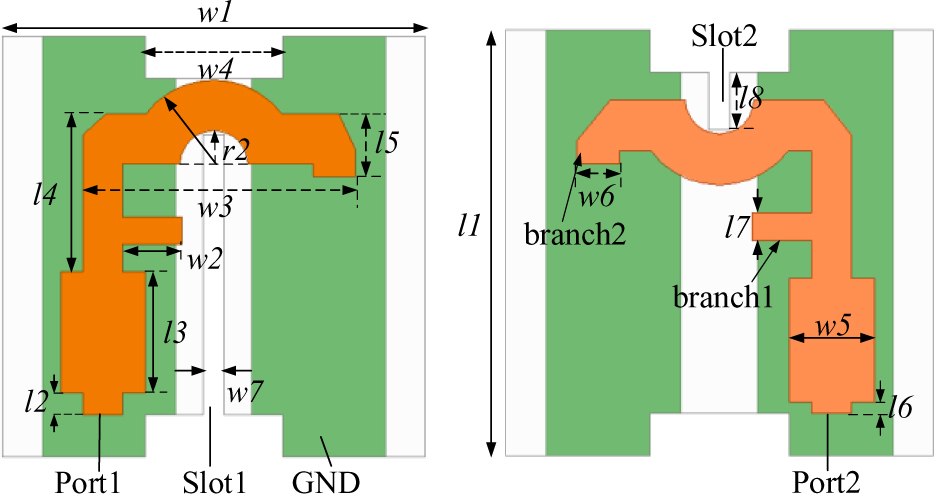
Figure 2: Feeding structure for port1 and port2.
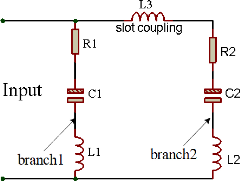
Figure 3: Equivalent ac circuit diagram of feeding structure.
Beneath the substrate, the reflector is composed of two squares with sizes of 24 24 mm and 94 104 mm stacked up and down to improve the isolation and realize a unidirectional radiation. And they are fixed at a distance of 16 mm and 21 mm (about one-quarter-wavelength at the centre frequency of 4.5 GHz and 3.45 GHz) below the antenna, respectively. A cylindrical through-hole with a diameter of 2 mm on the ground and reflector is convenient for connection.
To better understand the working principle of the feeding lines, the equivalent ac circuit diagram of the feeding structure is given in Fig. 3. In the feeding structure, the open branches, branch1 and branch2, can be equivalent to an Inductance-capacitance (LC) resonance circuit.
In addition, the slot coupling can be seen as inductance. Each open branch can be equivalent to LC resonant circuit, in which the resonance points of branch1 and branch2 correspond to low frequency band and high frequency band, respectively. In the low-frequency band, the capacitance is generally regarded as a parallel-plate structure, which is influenced by plate area A, the distance between plates d, and the dielectric constant filled by the plates [29]. Inductance is generally related to the structure of the coil, as shown in formulas (1) and (2):
| (1) | ||
| (2) |
The value of quality factor Q and resonance frequency f can be obtained according to the series equivalent circuit in Fig. 3, as shown in formulas (3)and (4):
| (3) | ||
| (4) |
According to the principle of Yagi antenna, the designed director is composed of a circular patch and four L-shaped metallic strips in Fig. 8. And the director is fixed above the radiator and the location of the convex reflector equal height 16mm. The connection is made by PA66 nylon cylinder, and its relative dielectric constant is about 40. The size of the designed dipole and director are both 60mm. From the literature [25–27], we can get the gain improvement calculation formula of circular director as follows.
| (5) | ||
| (6) | ||
| (7) | ||
| (8) |
where B, , are the thickness, relative permittivity, and permeability of the lower layer, respectively. ; is the frequency deviation parameter, and f is near by the centre frequency f.
In this paper, the upper layer of the director can be regarded as air, so the and can be equivalent to 1. It can be seen from Fig. 11 (b) that the designed is almost the same as the gain of the circular director. Refer to (5-8), it can be calculated that one layer of director yields an approximate enhancement of 0.78 dB. The experimental result is verified.
Table 1: Geometric parameters of the proposed antenna (unit: mm)
| Parameter | Value | Parameter | Value | Parameter | Value | Parameter | Value | Parameter | Value |
| l9 | 80 | h4 | 16 | l7 | 1.3 | R | 7 | m1 | 2.5 |
| h1 | 1 | l6 | 0.5 | l8 | 12 | h3 | 21.35 | l4 | 8.4 |
| l5 | 3.03 | s4 | 1.5 | h2 | 3.4 | l2 | 1 | w6 | 2 |
| x3 | 6 | gl | 104 | wl | 20 | w4 | 6.5 | r | 18 |
| gw | 94 | l1 | 20 | w3 | 12.875 | r2 | 1.6 | l | 60 |
| w7 | 1 | m2 | 18 | l8 | 2.7 | l3 | 5.8 | w5 | 4 |
The simulations are carried out by full-wave simulation software HFSS 15.0. And the direct solver is used for simulation design. The optimized geometric parameters of the proposed antenna are shown in Table 1.
III. RESULTS AND DISCUSSION
Figure 4 shows the evolution process of the dipole and the corresponding S-parameter simulated results. Ant.1 excites a frequency point in the high frequency band above 5G, and Ant. 2 and Ant. 3 are obtained by improving the shape of the radiation patch, which can change the surface current path of the patch. The surface current path becomes longer and the low-frequency points are excited. As can be seen from the Fig. 4, the reflection coefficient of Ant.2 and Ant.3 are obviously better than that of Ant.1, and dual-band has appeared. The improvement of bandwidth and the isolation of high frequency band significantly increases by chamfering and slotting. Considering that Ant.3 can better cover 5G range (3.3-3.6 GHz). So, Ant.3 is the designed dipole in this paper.
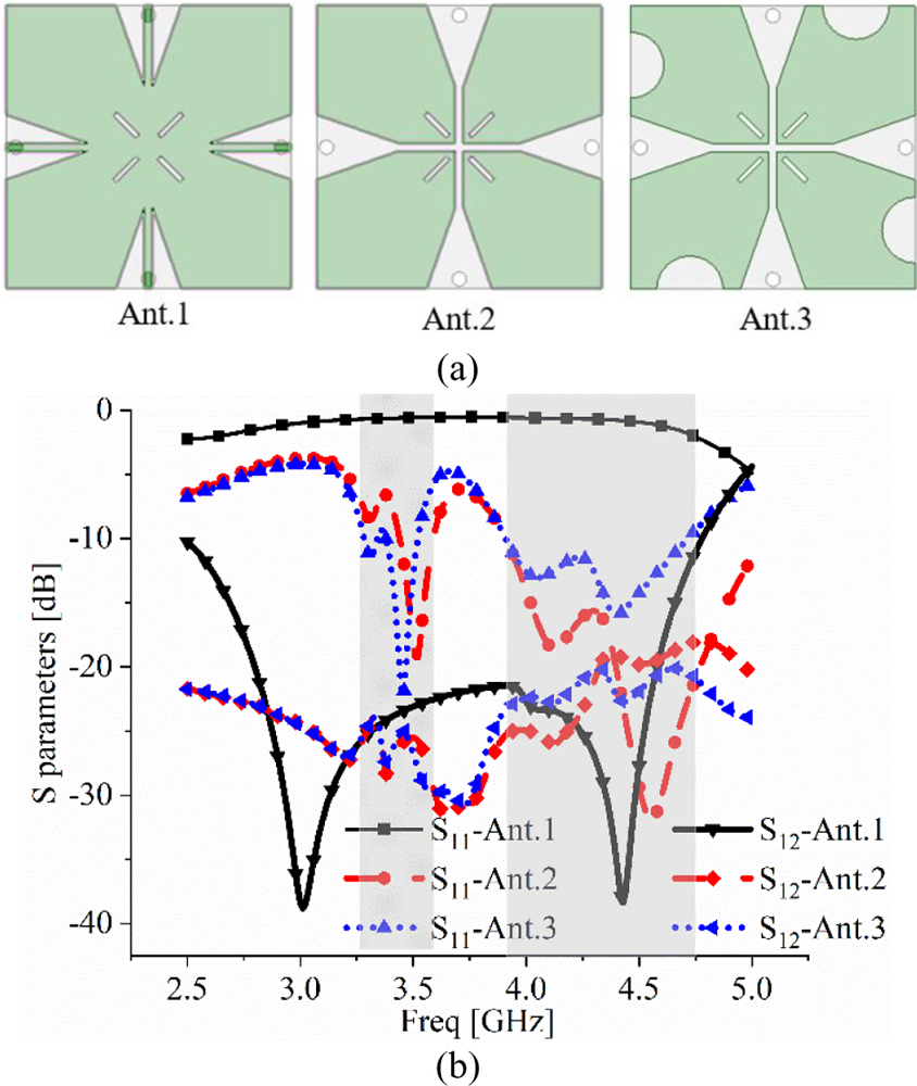
Figure 4: Dipole structures in evolution processes and simulated results.
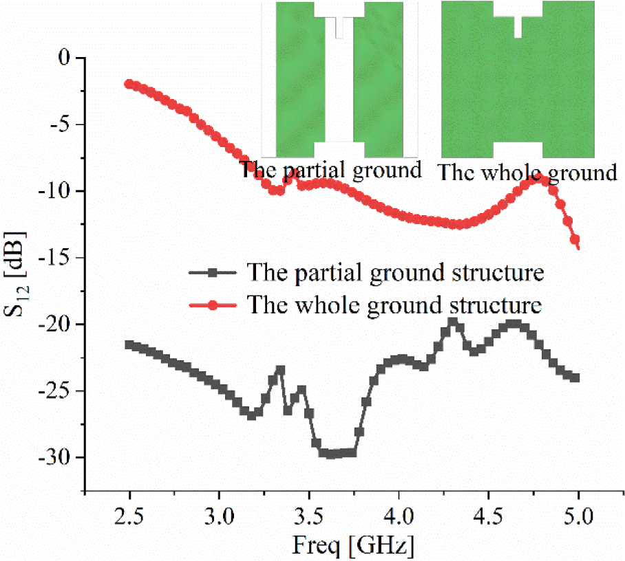
Figure 5: Effects on the whole antenna isolation with different ground structure.
Figures 6 and 7 show reflection coefficient and surface current distribution of different x3 values, respectively. As can be seen from the figure, when the value of x3 decreases, dual frequency bands shift toward the low frequency. In addition, when the value of x3 decreases, the current intensity at the slot and chamfer is stronger and the current path is longer, so the frequency point moves to the low frequency. Because the size parameter of the radiation structure has a great influence on the operating frequency of the antenna, the different value of the radiation parameters l is studied with HFSS 15.0. As shown in Fig. 8, with increasing l, the two resonant frequency bands move to the low frequency band, and the frequency variation range is large. As shown on Fig. 9, we can achieve better impedance matching of the antenna by adjusting the value of R.
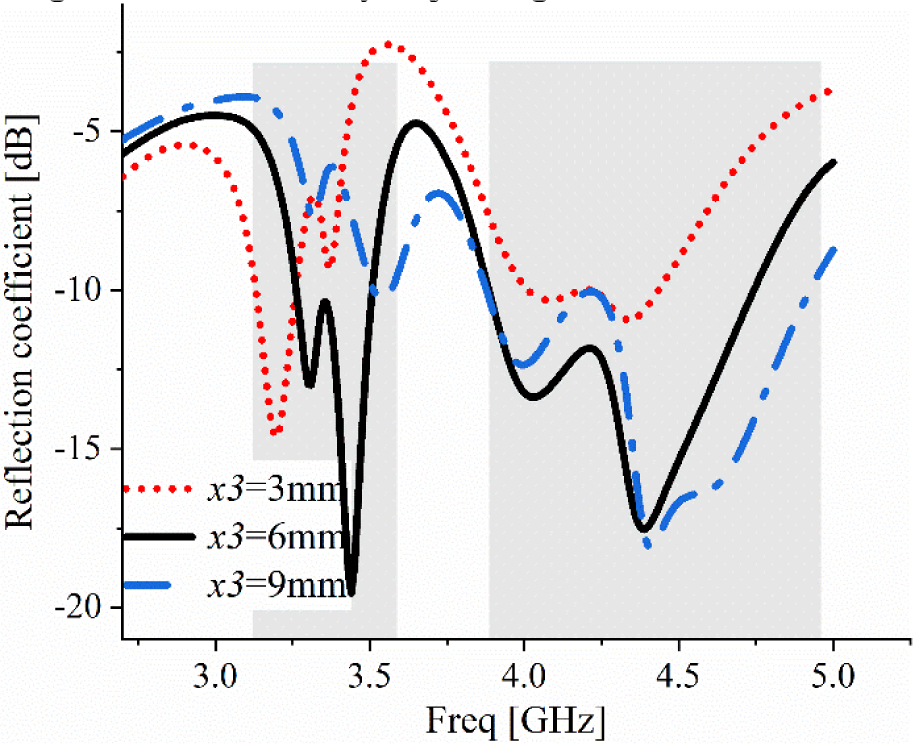
Figure 6: Effects of dipoles on S value with different value of x3.

Figure 7: Patch surface current distribution diagram with different value of x3.
Figure 10 conveys the isolation curves for different reflector shapes. As can be seen from the plot, the isolation of the stepped reflector in the high frequency band and low frequency band is higher than the planar reflector of about 15 dB and 5 dB, respectively.
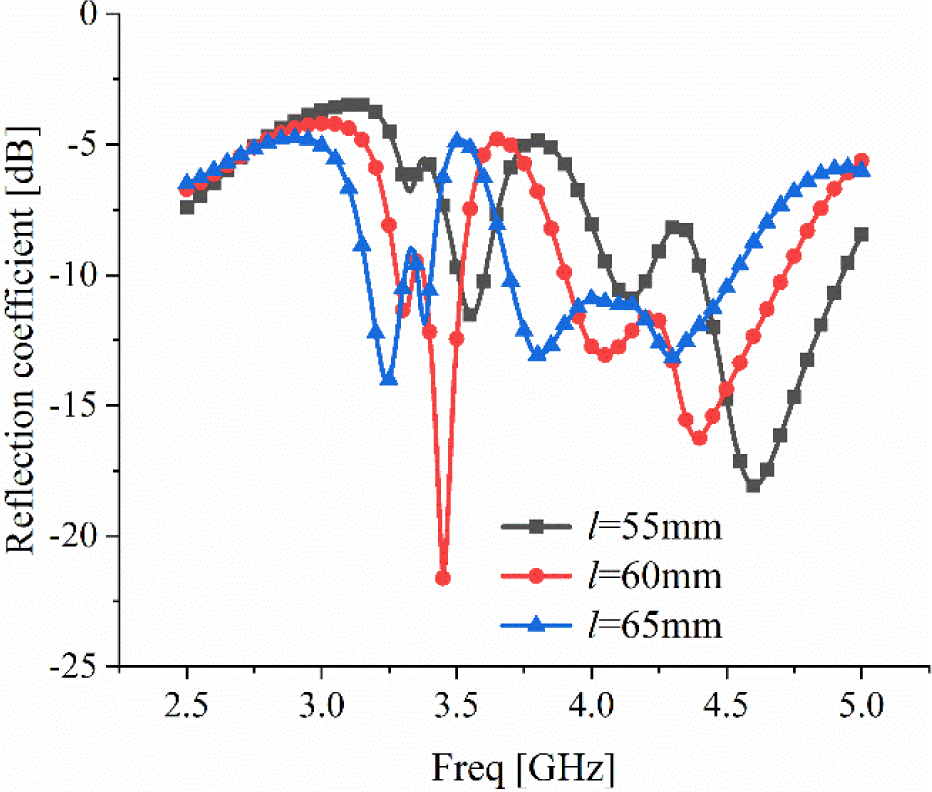
Figure 8: Effects on reflection coefficient value with different value of l.
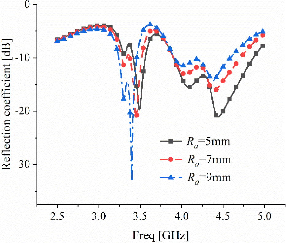
Figure 9: Effects on reflection coefficient value with different value of R.
Because the convex part mainly plays a very great role in the high frequency band. Although the isolation of the stepped reflector is only higher than that without reflector of 5 dB. As can be seen from the Fig. 11 (a), the gain of the stepped reflector is increased by nearly 8 dB compared with that without reflector, and the sidelobe is well suppressed. The simulated gain with stepped reflector, planar reflector and without reflector are 10.03, 6.58 and 2.13 dBi, respectively. And the corresponding sidelobe values are , and 1.12 dBi. According to the experiment, the side lobe of the proposed antenna is not only suppressed to a great extent, but also the simulated gain of the antenna in the 0 direction is greatly enhanced.
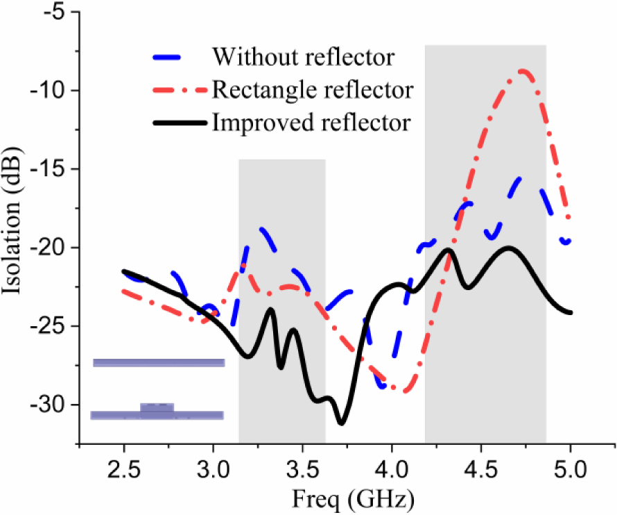
Figure 10: Comparison of isolation curves: without reflector, planar reflector, and stepped reflector.
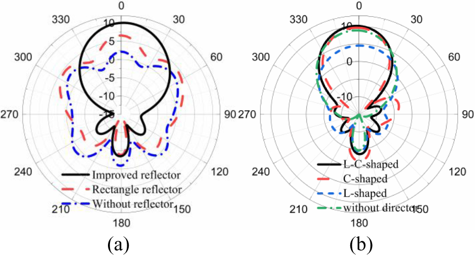
Figure 11: Radiation pattern: (a) reflector structure, (b) director structure.
In order to analyze the function and mechanism of the directors, the effect of the different shaped directors is studied and fixed at a height of 16 mm (about one quarter wavelength at the centre frequency). To facilitate the comparison, the overall dimensions of the three directors are exactly same. At 3.44 GHz, the radiation-pattern performance is compared with three different structures and without a director, including L-shaped metallic strips (L-shaped), circularly shaped (C-shaped), and a combination of both directors (L+C-shaped), as shown inFig. 11 (a).
It can be seen from the Fig. 11 (a) that the gain value with the director structure is 0.78 dBi higher than that without. It is close to the gain increase calculated by the formula (5) above. Each director has the highest gain which reached 10.4 dBi, while the lowest gain is 8.91 dBi. Compared with the circularly shaped director, a 90 bending strip microstrip line is placed at the diagonal of the patch to increase the gain and reduce the sidelobe value.
Figure 12 depicts the impedance matching of different director structures. The different structure of the director has a great influence on the frequency offset of the low frequency band, while for the high frequency band, the influence of frequency offset is not very large. Especially in the circularly shaped director, the addition of four L-shaped metallic strips makes the value of high frequency reflection coefficient greater. From the Fig. 13, we studied the antenna performance of the director by varying its parameter ‘r’, where ‘r’ refers to the maximum distance from the centre to the boundary in the circle. It can be clearly from Fig. 13 that the overall gain in the low frequency band of 3.2-3.52 GHz is higher than that in the high frequency band of 3.86-4.6 GHz. Considering the performance of bandwidth and gain, the most appropriate ‘r’ value is 18 mm. It can be found that the directors composed of a circle patch and a bending microstrip can achieve the effect of broadening the beamwidth and improving the gain.
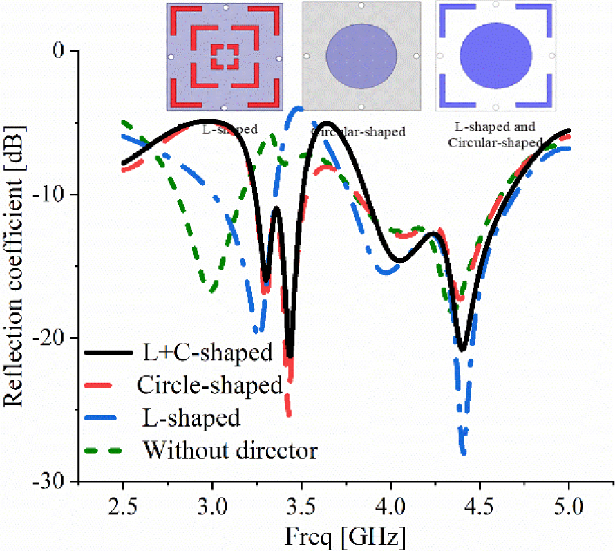
Figure 12: Comparison of reflection coefficient and radiation pattern between different director structure and without director.
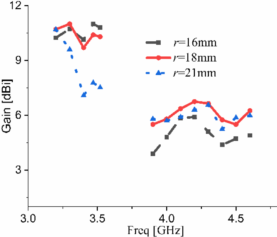
Figure 13: Gain comparison of the director with different radius.
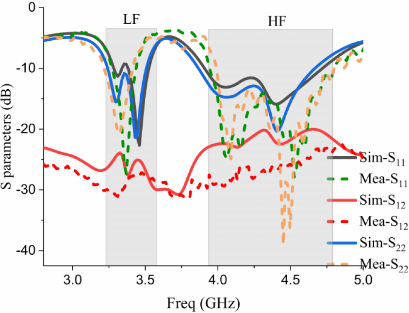
Figure 14: Simulated and measured S parameters of the antenna.
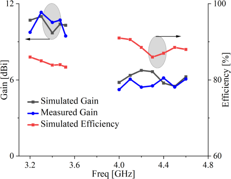
Figure 15: Simulated and measured gain and efficiency of the antenna.
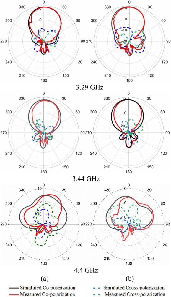
Figure 16: Radiation patterns at 3.29 and 3.44 GHz in the yoz plane (a) +45 polarization, (b) polarization.
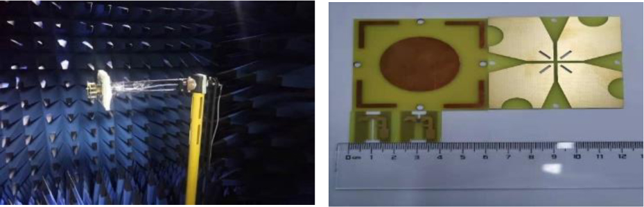
Figure 17: Antenna undergoing testing and fabricated prototype of antenna.
Figure 14 illustrates the simulated and measured S parameters characteristics of the two ports. As can be seen from the S-parameter diagram, the simulated bandwidth of low frequency band and high frequency band is 9.5% (3.20–3.52 GHz) and 17.5% (3.86–4.6 GHz), respectively. The measured bandwidth is 4.47% (3.28–3.43 GHz) and 18.1% (3.97–4.76 GHz), respectively. Compared with the simulated low frequency, the measured low-frequency offset is approximately 0.2 GHz. The low frequency band of the paper can cover the applicable band of 3.3-3.6 GHz of 5G band proposed by China’s IMT propulsion group that is studying the frequency bands including 3.3-3.6 GHz, 4.4-4.5 GHz, 4.8-5 GHz. But the bandwidth of 300 MHz is far from enough, we hope to make more use of the selected frequency band. Therefore, the dual band function realized in this paper can solve the problem of low band utilization, and provide a great reference for the future application of 5G base station antenna.
As described in Fig. 15, the average gain is approximately 10.2 dBi in the low frequency band, and the high frequency band is around 6.37 dBi. Lower antenna gain is mostly due to the fact that the sectional area of the stepped reflector acting on the high-frequency band is much smaller than that of the radiator, which cannot enhance the gain of the whole frequency band of the high frequency band. And the results of simulated and measured gains are in good agreement. Moreover, the efficiency of the antenna reaches an average of 86% in the entire frequency band.
Table 2: Summary of the radiation characteristic of the proposed antenna
| Frequency (GHz) |
Half-Power Beam-width | Cross-polarization Level(dB) | Back-Lobe Radiation Level(dB) | Peak Gain (dBi) | |
| Port 1(45) | Port 2(-45) | ||||
| 3.29 GHz | 52 | 57 | 11.22 | ||
| 3.44 GHz | 53 | 55 | 9.43 | ||
| 4.4 GHz | 149 | 158 | 6.15 | ||
Table 3: Comparison of several antennas
| References | Bandwidth (GHz) | Radiator Size (mm) |
Gain (dBi) | Isolation (dB) | Type of Director |
| [9] | 1.71-2.69 | 140 | 8.5 | 25 | Four rectangles |
| [20] | 1.7-2.69 | 55 | 8 | 22 | Square director |
| [21] | 1.61-3.45 | 78.99 | 5.87 | / | Square director |
| Proposed | 3.2-3.52/3.86-4.6 | 60 | 10.52/6.37 | 26/22 | L+C-shaped |
Since the radiation patterns between the xoz-plane and the yoz-plane are similar, the radiation pattern of the two ports of the proposed antenna on the yoz-plane at 3.2 GHz, 3.44 GHz and 4.4 GHz are given in Fig. 16. And when one port is excited to measure the radiation pattern, while other port is terminated to 50 . when the antenna operates at 3.29 GHz and 3.44 GHz, the two ports of the antenna exhibit good directional radiation characteristics in the yoz-plane. And the directivity of the antenna is largely strong, maximum direction of radiation points to , peak gain is 10.52 dBi at 3.29 GHz, that of the corresponding back lobe level is -7.05 dBi. Although the directionality of 4.4 GHz is not as strong as the former, the half power beam width (HPBW) is three times that of the former, and the network coverage is wider, which can be well used in real life. Meanwhile, the zero points of the yoz-plane obtained by simulation and measurement are very consistent at three frequency points. The maximum gain of the antenna at 3.29, 3.44 and 4.4 GHz is 10.52, 11.04 and 6.37 dBi, respectively. The measured HPBW at the frequency points is several degrees smaller than that of the simulation. As can be seen from Fig. 16, the direction coefficient of the measured radiation pattern is much smaller than that of the simulated one, and the gain is reduced by approximately 2.24 dBi. But the radiation patterns are relatively stable at 3.29, 3.44, and 4.4 GHz. Figure 17 shows the fabricated prototype of the antenna and antenna undergoing testing. Overall, the performance consistency between the port 1 and port 2 is a good agreement. Detailed radiation characteristics of the proposed antenna are summarized in Table 2.
Discrepancy between simulation and measurement results is observed at some angles. It is obvious that the simulated and measured results exist in relatively minor differences. The reasons for the difference possibly are caused by the following: First, welding and FR-4 processing and other process errors; second, consistency error of the antenna’s dielectric material and transmission line; and, third, reduction degree of the simulation software, and systematic error of the testing instrument. Hence, there is a certain inconsistency between the simulated and the measured results.
Table 3 compares the prototype with the base station antenna published papers in recent years. In [9], four rectangle parasitic elements are placed beside the main radiation to enhance the gain of the dual-polarized antenna; however, this method increases the overall size of the antenna. But in the design of references [20], [21] and this paper, loading the director above the radiation element can not only enhance the gain, but also reduce the size of the antenna. Compared to these antennas, the proposed antenna has more compact size, higher isolation and gain.
IV. CONCLUSION
A wideband dual-polarized dipole with a director and a stepped reflector structure has been proposed herein. The experimental results demonstrate that the proposed designs have two frequency bands with excellent matching, gain and isolation characteristics. The dual band coverage can be applied to the application of 5G frequency band in the future. The good performance of the proposed antenna allows it to be used for a wide range of wireless detection, transmission and communication.
ACKNOWLEDGMENTS
This work was supported by the Natural Science Key Foundation of Fujian Province Grant with No. 2020J02042, Research on integration design and industrialization of RF components for 5G wireless communication terminal Grant with No. S22042, and the Natural Science Foundation of Fujian Province of China with Grant No. 2021J05179.
REFERENCES
[1] M. Duarte, C. Dick, and A. Sabharwal, “Experiment-driven characterization of full-duplex wireless systems,” IEEE Trans. on Wireless Communications, vol. 11, no. 12, pp. 4296-4307, 2012.
[2] K. Fujimoto and J. R. James, “Mobile antenna systems handbook,” Artech House: 2001.
[3] J. Qi, J. Pan, Y. Li, and G.-L. Huang, “A wideband base station antenna loaded with bow-tie-like parasitic elements,” Applied Computational Electromagnetics Society (ACES) Journal, 2022.
[4] X. D. Yang, Y. S. Li, Q. T. Li, and C. Y. Liu, “Analysis and experimental investigation on a novel wideband sleeve dipole array antenna,” AEU- International Journal of Electronics and Communications, vol. 65, no. 4, pp. 373-376, 2011.
[5] Y. S. Li, X. D. Yang, C. Y. Liu, and T. Jiang, “A sleeve monopole antenna with wide impedance bandwidth for indoor base station applications,” Progress in Electromagnetics Research C, vol. 16, pp. 223-232, 2010.
[6] B. Qiu, S. Luo, and Y. Li, “A broadband dual-polarized antenna for Sub-6GHz based station application,” IEEE 3rd International Conference on Electronic Information and Communication Technology (ICEICT 2020), 13-15th, November, Shenzhen, China, 2020.
[7] D. Z. Zheng and Q. X. Chu, “A wideband dual-polarized antenna for base station applications,” IEEE International Conference on Computational Electromagnetics (ICCEM), pp. 268-271, 2016.
[8] S. Chen and K. M. Luk, “High performance dual-band dual-polarized magneto-electric dipole base station antenna,” Microwave Conference (APMC), Sendai, Japan, pp. 321-323, 2015.
[9] Y. Luo, Q.-X. Chu, and D.-L. Wen, “A plus/minus 45 degree dual-polarized base-station antenna with enhanced cross-polarization discrimination via addition of four parasitic elements placed in a square contour,” IEEE Trans. Antennas Propag., vol. 64, no. 4, pp. 1514-1519, 2016.
[10] E. Yetisir, C. C. Chen, and J. L. Volakis, “Wideband dual-polarized omnidirectional antenna with very high isolation across 1.65-2.7 GHz,” IEEE Antennas and Propagation Society International Symposium (APSURSI), pp. 1123-1124, 2014.
[11] Z. Nie, H. Zhai, L. Liu, J. Li, D. Hu, and J. Shi, “A dual-polarized frequency-reconfigurable low-profile antenna with harmonic suppression for 5g application,” IEEE Antennas Wireless Propag. Lett., vol. 18, no. 6, pp. 1228-1232, 2019.
[12] Y. Chung, S. S. Jeon, D. Ahn, J.-I. Choi, and T. Itoh, “High isolation dual-polarized patch antenna using integrated defected ground structure,” IEEE Microw. Wireless Compon. Lett., vol. 14, no. 1, pp. 4-6, 2004.
[13] L. Peng, C. L. Ruan, and Z. Q. Li, “A novel compact and polarization-dependent mushroom-type ebg using csrr for dual/triple-band applications,” IEEE Microw. Wireless Compon. Lett., vol. 20, no. 9, pp. 489-491, 2010.
[14] K. Yu, Y. Li, X. Liu, “Mutual coupling reduction of a MIMO antenna array using 3-D novel meta-material structures,” Applied Computational Electromagnetics Society (ACES) Journal, vol. 33, no. 7, pp. 758-763, 2018.
[15] T. Jiang, T. Jiao, Y. Li, and W. Yu, “A low mutual coupling MIMO antenna using periodic multi-layered electromagnetic band gap structures,” Applied Computational Electromagnetics Society (ACES) Journal, vol. 33, no. 3, pp. 305-311, 2018.
[16] H. Zhai, K. Zhang, and S. Yang, “A low-profile dual-band dual-polarized antenna with an amc surface for wlan applications,” IEEE Antennas Wireless Propag. Lett., pp. 2692-2695, 2017.
[17] P. Chen, L. Wang, and T. Ding, “A broadband dual-polarized antenna with CRR-EBG structure for 5G applications,” Applied Computational Electromagnetics Society (ACES) Journal, vol. 35, no. 12, pp. 1507-1512, 2021.
[18] Y. Gou, S. Yang, and J. Li, “A compact dual-polarized printed dipole antenna with high isolation for wide band base station applications,” IEEE Trans. Antennas Propag., vol. 62, no. 8, pp. 4329-4395, 2014.
[19] Y. He, Z. Pan, and X. Cheng, “A novel dual-band, dual-polarized, miniaturized and low-profile base station antenna,” IEEE Trans. Antennas Propag., vol. 63, no. 12, pp. 5399-5408, 2015.
[20] Y. Liu, Y. Hao, and F. W. Wang, “A novel miniaturized broadband dual-polarized dipole antenna for base station,” IEEE Antennas Wireless Propag. Lett., vol. 12, no. 4, pp. 1335-1338,2013.
[21] H. Huang, Y. Liu, and S. Gong, “A broadband dual-polarized base station antenna with sturdy construction,” IEEE Antennas Wireless Propag. Lett., vol. 16, pp. 665-668, 2017.
[22] H. Zhai, L. Xi, and Y. Zang, “A low-profile dual-polarized high-isolation mimo antenna arrays for wideband base-station applications,” IEEE Trans. Antennas Propag., vol. 66, no. 1, pp. 191-202, 2018.
[23] H. Liu, S. Gao, and T.-H. Loh, “Small director array for low profile smart antennas achieving higher gain,” IEEE Trans. Antennas Propag., vol. 61, no. 1, pp. 162-168, 2013.
[24] G. Feng, L. Chen, and X. Wang, “Broadband circularly polarized crossed bowtie dipole antenna loaded with parasitic elements,” IEEE Antennas Wireless Propag. Lett., vol. 17, no. 1, pp. 114-117, 2018.
[25] K. Olivier, D. Tarek, and K. Wu, “Vertically multilayer-stacked yagi antenna with single and dual polarizations,” IEEE Trans. Antennas Propag., vol. 58, no. 4, pp. 1022-1030, 2010.
[26] D. R. Jackson and N. G, Alexopoulos, “Gain enhancement methods for printed circuit antennas,” IEEE Trans. Antennas Propag., vol. 33, no. 9, pp. 976-987, 1985.
[27] H. K. Kan, R. B. Waterhouse, and A. M. Abbosh, “Simple broadband planar cpw-fed quasi-yagi antenna,” IEEE Antennas Wireless. Propag. Lett., vol. 6, pp. 18-20, 2007.
[28] P. Chen, L. Wang, and Z. Ma, “Reconfigurable planar monopole antenna for fifth-generation mobile communication system,” Applied Computational Electromagnetics Society (ACES) Journal, vol. 36, no. 1, pp. 67-74, 2021.
[29] P. Chen, L. Wang, and T. Ding, “A broadband dual-polarized antenna with CRR-EBG structure for 5G applications,” Applied Computational Electromagnetics Society (ACES) Journal, vol. 35, no. 12, pp. 1507-1512, 2020.
BIOGRAPHIES

Peng Chen received the M.S. and Ph.D. degrees in electromagnetic field and microwave technology from the Harbin Engineering University, Harbin, China. Since 2017, he has been an Associate Professor with the College of Information Engineering, Jimei University.
His research interests include antennas, millimeter-wave reconfigurable devices, and radio frequency microwave circuits.

Lihua Wang received the B.S. degree from the School of electronic information and electrical engineering, Xiangnan University, Hunan, China. She is now a master student with the College of Information Engineering, Jimei University. Her research interests include base station antennas and liquid crystal antennas.

Yumeng Lin received the B.S. degree from the School of Automobile Service engineering, Xi’an Aeronautical University, Shaanxi, China. She is now a master student with the College of Navigation, Jimei University. Her research interests include base station antenna and Planar microstrip antenna.

Dan Wang received the B.S. degree from the School of electronic and information electrical engineering, Wuyi University, Fujian, China. She is now a master student with the College of Information Engineering, Jimei University. Her research interested in antenna for body communication.
ACES JOURNAL, Vol. 37, No. 6, 733–742.
doi: 10.13052/2022.ACES.J.370609
© 2021 River Publishers