A Wideband Base Station Antenna Loaded with Bow-Tie-Like Parasitic Elements
Junwei Qi1, Jiakang Pan1, Yingsong Li2,*, and Guan-Long Huang3
1College of Information and Communication Engineering, Harbin Engineering University, Harbin 150001, China
2Key Laboratory of Intelligent Computing and Signal Processing Ministry of Education, Anhui University, Hefei, China
3School of AI-Guangdong & Taiwan, Foshan University, Foshan, Guangdong 528225, China
*liyingsong@ieee.org
Submitted On: April 18, 2022; Accepted On: September 24, 2022
Abstract
A 45 dual-polarization wideband antenna for 5G base station application is proposed using cross dipoles, bow-tie-like parasitic elements and baluns. The antenna is modeled, simulated, and optimized for an optimal size of 115 mm 115 mm 27.8 mm. A 10dB bandwidth is obtained to cover 2.24GHz-3.75GHz, which has a fractional bandwidth of 50.4%. In the design, bent -shaped microstrip lines are to achieve higher isolation that is better than 25dB. The proposed antenna is fabricated and measured to get a result that it has a wide bandwidth, good directional radiation patterns, and a high peak gain of 8.1±1.1dBi, making it suitable for 5G base station applications.
Index Terms: 5G application, ±45∘ dual-polarized antenna, cross dipole antenna, wideband antenna.
1 INTRODUCTION
With the continuous improvement of communication technology, the requirements of BS antenna are also significantly elevated. Especially, in the 5G era, for the sake of achieving a higher data transmission rate, the operation bandwidth of the BS antenna must be improved [1]–[2]. For enhancing the operating bandwidth of the BS antenna, pattern distortion, cross-polarization deterioration, and decreasing the front-to-back ratio (FBR) are always found in the previous designs. Therefore, the wideband base station antenna research is a hot topic for 5G applications [3]. For 5G applications, a dual-polarized antenna is widely used in BS antennas, which can provide diversity gain and reduce the impact of the multipath effect on the system [4]. Till now, dual-polarized antennas can be divided into 45 polarization or horizontal and vertical polarization on the base of polarization direction. In addition, the dual-polarized antenna can also be divided into cross dipole type [5]–[6], microstrip type [7], and slot type [8]. Among the three types of dual-polarized antennas, the cross dipole has been studied widely because of its high port isolation and directional radiation characteristics [9]-[11].
In the past decades, many dual-polarized BS antennas have been proposed [12]-[14]. A miniaturized cross dipole antenna is proposed in [15]. The antenna is installed in a dielectric resonant cavity to get an FBR of 22dB in the operating frequency band, with a bandwidth of 3.2GHz-3.7GHz. In [16], a broadband cross dipole antenna is proposed to get a 15dB impedance bandwidth range from 1.7GHz to 2.7GHz, and the fractional bandwidth reaches 48%. But the isolation of the dual-polarized port of the antenna is only 22dB. A folded dipole antenna with a metal reflector is proposed in the literature [17]. The antenna increases the resonance points and greatly improves the antenna impedance bandwidth by bending the dipole and adding via, which might deteriorate the radiating. In [18], a broadband and high isolation dual-polarized antenna is presented. Compared with the traditional dual-polarized antenna, the antenna employs a resonance ring and a square plate to expand bandwidth and improve directionality. However, its height is increased.
In this work, a wideband dual-polarized antenna consisting of a pair of T-shaped dipoles, bow-tie-like parasitic elements, microstrip baluns, and a box-like reflector is proposed, analyzed, fabricated, and measured. The cross dipoles are used as the main radiator, and the bow-tie-like parasitic elements are surrounded the cross dipoles to expand the bandwidth of the proposed antenna. The orthogonal microstrip baluns not only feed the upper radiator patches through coupling but also support the entire structure of the antenna, making the antenna easier to assemble and more stable. Also, -shaped microstrip lines are used to enhance the isolation of the antenna. In the operating frequency band, the gain is 8.11.1dBi, and the 3dB beam width is 635. In addition, due to the existence of a box-like metal reflector, the FBR of the antenna is higher than 17dB. Thus, the wideband BS antenna is suitable for 5G BS application.
2 ANTENNA DESIGN AND ANALYSIS
2.1 Antenna design
Figure 1 shows the configuration of the proposed dual-polarized antenna that is composed of cross dipoles, bow-tie-like parasitic elements, baluns, and a box-like metal reflector. A pair of balun is placed orthogonally to feed the radiation structure and support the antenna. All the baluns, dipoles, and parasitic elements are created on FR4 with relative permittivity = 4.4 and loss tangent =0.02, whose thickness is 0.8 mm thick as the FR4. The box-like reflector is welded by a 115 mm115 mm copper base plate and four 115 mm 16 mm copper coamings. The thickness of all copper plates is 0.8 mm. The box-like metal reflector enables the cross dipole antenna to radiate directionally in the +Z axis direction.
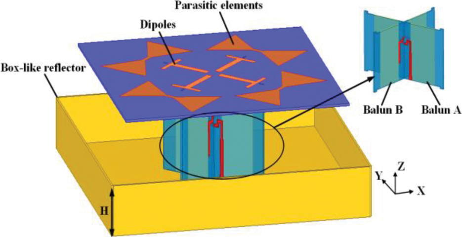
Figure 1: Configuration of proposed antenna.
The detailed configuration of the radiation structure is shown in Fig. 2 (a). Four T-shaped patches form pairs of cross dipoles, which are surrounded by bow-tie-like parasitic elements. In Fig. 2 (b), two circular holes are drilled to connect with the 50- coaxial line. The inner conductor of the 50- coaxial line will be connected with a -shaped microstrip line through a circular hole, and the outer conductor will be connected with the box-like reflector. Four rectangular slots are used to fix the antenna.
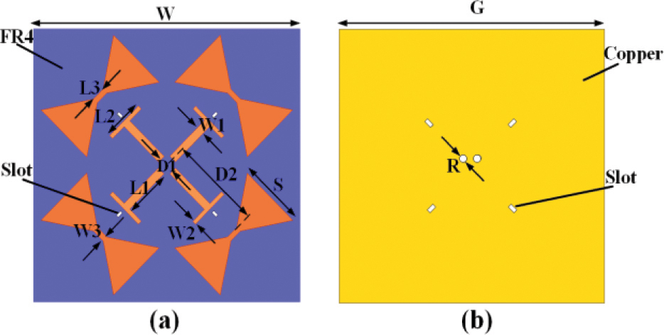
Figure 2: (a) Configuration of the radiation structure. (b) Configuration of the reflector base plate.
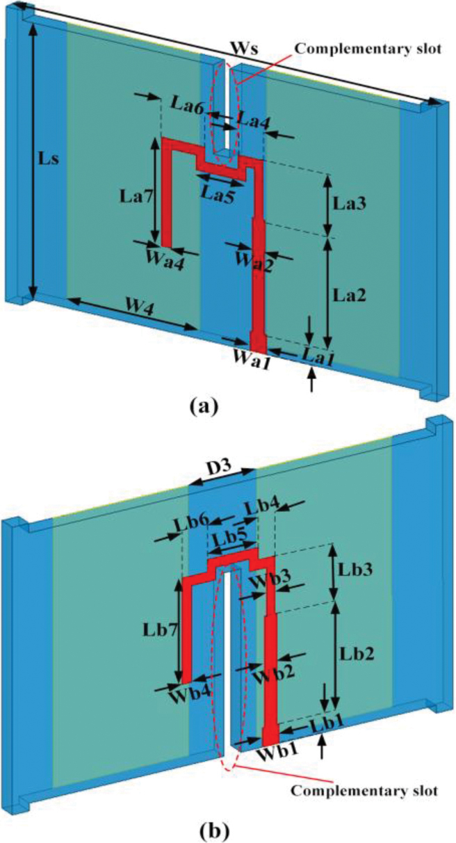
Figure 3: Configuration of the baluns, (a) balun A and (b) balun B.
Figures 3 (a) and (b) present the feeding baluns for implementing the dual polarization. The -shaped microstrip lines are printed on one side of FR4, while two thin rectangular copper sheets are printed on the other side of the FR4. Two complementary slots are etched in the middle of the balun sheets to provide a convenient installation for the constructed antenna. In addition, four corners of the FR4 of baluns have bumps which are connected with the rectangular slots on the FR4 of radiating layer and a box-like metal reflector to give stable support for the constructed antenna.
The antenna is created in the HFSS, and it is optimized to achieve a good performance. The details of the geometric dimensions of the proposed antenna are shown in Table 1. The overall size of the antenna is 115 mm115 mm 27.8 mm.
Table 1: Optimized parameters for the geometric parameters of the antenna
| Parameters | H | W | G | R | S | W1 | W2 |
| Value(mm) | 16 | 100 | 115 | 1.84 | 24 | 3 | 1.5 |
| Parameters | W3 | W4 | L1 | L2 | L3 | D1 | D2 |
| Value(mm) | 2 | 16 | 18 | 15 | 5 | 6 | 34 |
| Parameters | D3 | WS | LS | Wa1 | Wa2 | Wa3 | Wa4 |
| Value(mm) | 8 | 52 | 26 | 1.5 | 0.8 | 0.5 | 0.7 |
| Parameters | Wb1 | Wb2 | Wb3 | Wb4 | La1 | La2 | La3 |
| Value(mm) | 1.5 | 1 | 0.5 | 0.7 | 2 | 11.5 | 5.5 |
| Parameters | La4 | La5 | La6 | La7 | Lb1 | Lb2 | Lb3 |
| Value(mm) | 2 | 5 | 3.7 | 11 | 2 | 11.5 | 5.5 |
| Parameters | Lb4 | Lb5 | Lb6 | Lb7 | |||
| Value(mm) | 2 | 5 | 3.7 | 11 |
2.2 Antenna analysis
To better illustrate the implementation principle of the wideband BS antenna, the radiation structure design procedure of the antenna is presented in Fig. 4. ANTA_1 only consists of four T-shaped patches to form a pair of cross dipoles to achieve 45 polarization. Then, rectangle parasitic elements are used to form ANTA_2. At last, the rectangle parasitic elements are modeled to be bow-tie-like parasitic elements for the proposed antenna with a name of ANTA_3.
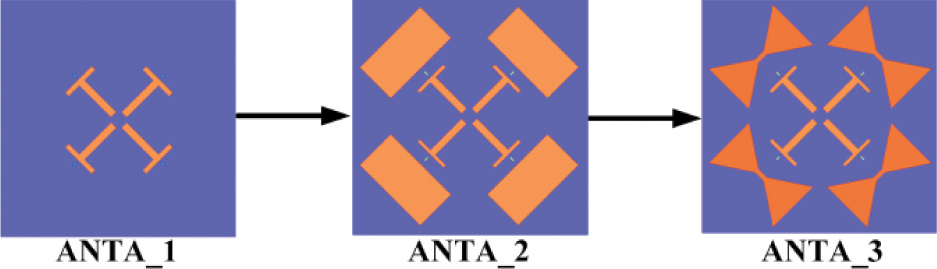
Figure 4: Evolution of the antenna radiation structure.
Then, the principle of the antenna is discussed based on the current distribution in Fig. 5 and Fig. 6. We can see that ANTA_1 has a resonance point at approximately 3.5GHz owing to the current distributions on the T-shaped dipoles. When we use the rectangle parasitic elements for ANTA_2, the current path are expanded to the parasitic elements, and hence the bandwidth of the antenna is increased. In the same method, bow-tie-like parasitic elements are adopted in ANTA_3 to enhance the bandwidth of the proposed antenna.
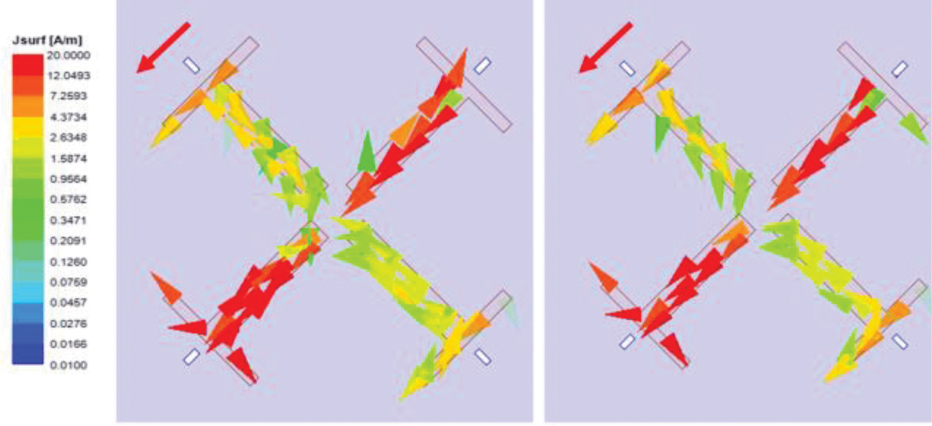
Figure 5: Surface current distribution, (a) 3.2GHz, ANTA_1, (b) 3.5GHz, ANTA_1.
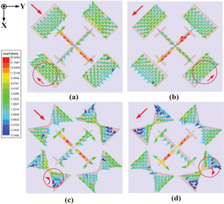
Figure 6: Surface current distribution in 3.5GHz. (a) The ANTA_2 with only port 1 excitation. (b) The ANTA_2 with only port 2 excitation. (c) The proposed antenna with only port 1 excitation. (d) The proposed antenna with only port 2 excitation.
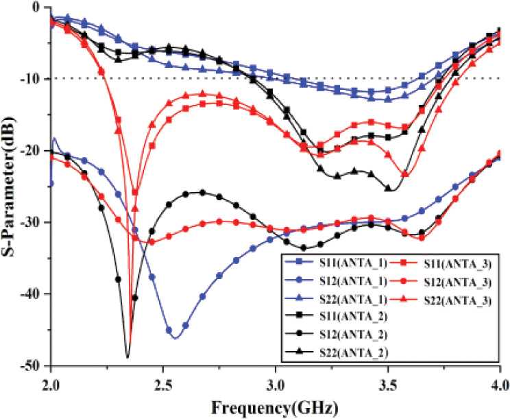
Figure 7: Simulated S-parameters of ANTA_1, ANTA_2, and ANTA_3.
On the basis of ANTA_2, ANTA_3 modifies the parasitic element to bow-tie-like shape. The S-parameter for the antenna at different design procedures are shown in Fig. 7. It is found that the ANTA_1 has only one resonant mode, and with a bandwidth of approximately 400MHz. For the ANTA_2, it has a new resonant mode to expand the bandwidth to around 600MHz. Finally, ANTA_3 employs bow-tie-like parasitic elements to further expand the bandwidth via providing another new resonant mode at lower frequency. As a result, a wider 10dB impedance bandwidth for the ANTA_3 is achieved, which operates from 2.24Ghz to 3.75GHz with a bandwidth of 1.51GHz.
Although the introduction of parasitic elements is beneficial to expand the operating bandwidth of the BS antenna, it will affect the radiation performance. In Figs. 6 (a) and (b), ANTA_2 with rectangular parasitic elements maintains the current distribution in the same direction as the T-shaped dipoles, while the other two parasitic elements have coupling currents in the opposite direction with respect to the current of dipoles. There is no doubt that reverse coupling current will affect the radiation performance of the antenna and reduce the pattern stability. As for proposed antenna, it uses bow-tie-like parasitic elements to give stable current distribution presented in Figs. 6 (c) and (d).
3 RESULT AND DISCUSSION
3.1 Antenna numerical simulation
For the sake of obtaining larger antenna bandwidth, it is necessary to analyze quantitatively the antenna parameters. Since the balun is the key element to realizing impedance matching, the balun parameters are mainly analyzed quantitatively.
L1 is a parameter that determines the length of the T-shaped dipole. The S-parameters of the antenna with different L1 are shown in Fig. 8. When L1 increases, the lowest frequency moves to the lower frequency, getting a larger bandwidth, and vice visa. The distance between T-shaped dipole and bow-tie parasitic element also affects the impedance matching of the antenna, which is demonstrated in Fig. 9 with varying D2. When D2 increases, the impedance bandwidth will be expanded slightly. The effect for different LS is presented and shown in Fig. 10, where we can see that the antenna has the best bandwidth for LS = 26 mm.
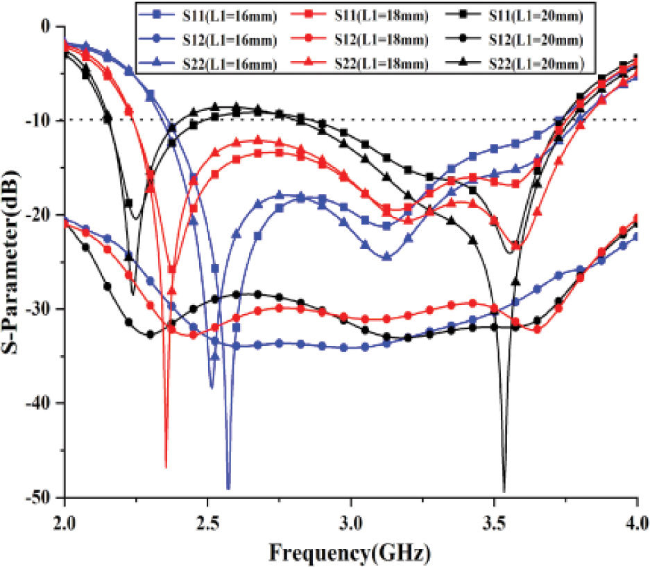
Figure 8: Simulated S-parameters of the proposed antenna with different L1.
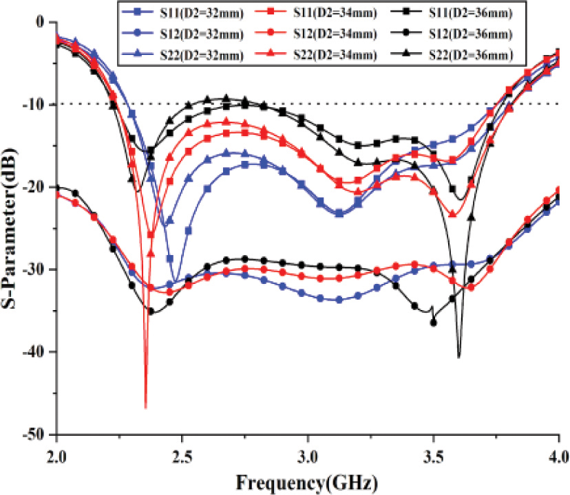
Figure 9: Simulated S-parameters of the proposed antenna with different D2.
3.2 Performance for the fabricated antenna
To verify the simulation results of the antenna, a prototype of the proposed antenna is manufactured and tested. Figure 11 shows and sets up the prototype antenna. The S-parameters of the prototype antenna are tested using the vector network analyzer-Agilent N5244A and compared with the simulation results in Fig. 13. The 10dB impedance bandwidth of simulation and measurement has a little difference that is caused by fabrications. In addition, within the operating bandwidth, the simulated isolation and measured isolation between the two ports is better than 25dB.
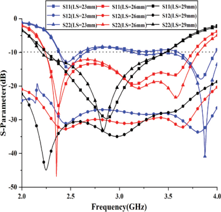
Figure 10: Simulated S-parameters of the proposed antenna with different LS.

Figure 11: Photograph of prototype antenna. (a) Antenna on test for S-parameters. (b) Antenna radiating performance on test.
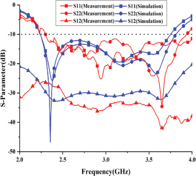
Figure 12: Simulated and measured S-parameters of the base station antenna.
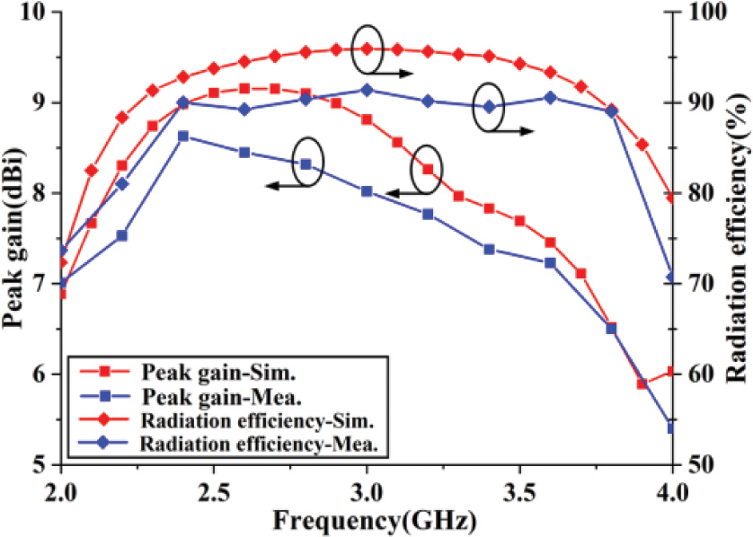
Figure 13: The peak gain and radiation efficiency of the BS antenna.
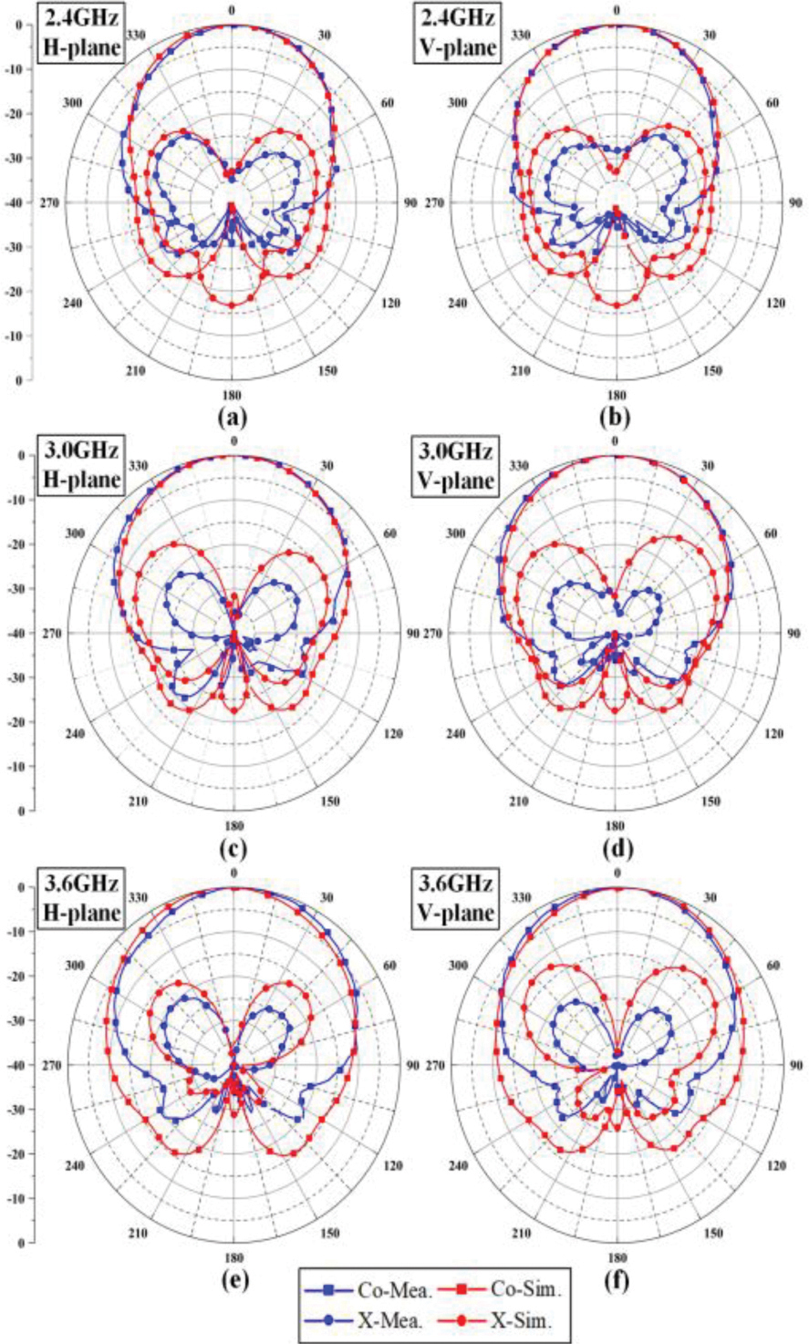
Figure 14: Simulated and measured radiation patterns at 2.4 GHz, 3.0 GHz and 3.6 GHz.
Figure 13 shows the simulated and measured peak gain and the radiation efficiency of the proposed antenna. In the operating frequency band, the simulated peak gain range is 8.11.1dBi and the 3dB beam-width of the antenna is 635. The measured peak gain is slightly lower than the simulation result, which is caused by the insertion loss caused by the fabrication of the prototype antenna. On the other hand, it can be seen in Fig. 13 that the radiation efficiency of the antenna in the operating bandwidth is higher than 90%. In Fig. 14, only the radiation patterns of port 1 at 2.4GHz, 3.0GHz, and 3.6GHz are given, since the antenna is symmetry between port 1 and port 2. It can be seen that the radiation patterns of the antenna have a high coincidence between the simulated result and the measured result. In addition, the cross-polarization discrimination (XPD) of the designed BS antenna is over 30 dB in the boresight direction. The achieved front-to-back-ratio (FBR) is better than 17dB, meaning that the back radiation of the proposed antenna is suppressed well. Table 2 shows the performance comparison between the proposed antenna and the existing dual-polarized antenna ( is the wavelength corresponding to the central frequency). It is to say that the proposed antenna is a wideband BS antenna with high gain, high isolation and low cross-polarization. In the future, the antenna can be used for MIMO radar and sparse arrays applications [21-22].
Table 2: Comparison of the proposed antenna with existing dual-polarized antennas
| Ref. | Operation band (GHz) | XPD (dB) | Isolation (dB) | Gain (dBi) | FBR (dB) | Profile height |
| [15] | 3.25-3.75 (11.4%) | 25 | 30 | 7 | 18 | 0.21 |
| [16] | 1.6-2.9 (48%) | 25 | 22 | 8.2 | 20 | 0.24 |
| [17] | 1.15-4.07 (107%) | 20 | NS | 8.2 | 11.5 | 0.38 |
| [18] | 1.71-2.69 (44.5%) | 25 | 22 | 8 | 18 | 0.39 |
| [19] | 1.68-2.75 (48%) | 20 | 37 | 8.90.7 | 15.5 | 0.18 |
| [20] | 3.28-3.71, 4.8-5.18 (12.3,7.6) | 20 | 37 | 8.71.8 | 13 | 0.13 |
| This work | 2.24-3.75 (50.4%) | 30 | 25 | 8.11.1 | 17 | 0.28 |
4 CONCLUSION
A wideband 45 dual-polarized cross dipole antenna is proposed in this paper and its impedance bandwidth is extended by parasitic elements and baluns. The proposed antenna adopts bow-tie parasitic elements, which improves the operating bandwidth of the antenna and solves the problem of parasitic elements affecting the radiation performance. The reflector improves the peak gain of the antenna and increases the stability of the antenna radiation pattern. The antenna has an impedance bandwidth of 50.4%, which can be operated at 2.24 GHz-3.75 GHz. Furthermore, the proposed antenna has a port isolation of more than 25dB and a high cross polar discrimination of better than 30 dB in the operating bandwidth. Furthermore, the antenna has a high gain, good directional radiation patterns, and front-to-back-ratio, making it promising for 5G base stationapplications.
REFERENCES
[1] F. Jia, S. Liao, and Q. Xue, “A dual-band dual-polarized antenna array arrangement and its application for base station antennas,” in IEEE Antennas and Wireless Propagation Letters, vol. 19, no. 6, pp. 972-976, Jun. 2020.
[2] Y. Zhu, Y. Chen, and S. Yang, “Decoupling and low-profile design of dual-band dual-polarized base station antennas using frequency-selective surface,” in IEEE Transactions on Antennas and Propagation, vol. 67, no. 8, pp. 5272-5281, Aug. 2019.
[3] Z. Li, J. Han, Y. Mu, X. Gao, and L. Li, “Dual-band dual-polarized base station antenna with a notch band for 2/3/4/5G communication systems,” in IEEE Antennas and Wireless Propagation Letters, vol. 19, no. 12, pp. 2462-2466, Dec. 2020.
[4] B. Lindmark and M. Nilsson, “On the available diversity gain from different dual-polarized antennas,” in IEEE Journal on Selected Areas in Communications, vol. 19, no. 2, pp. 287-294, Feb. 2001.
[5] Y. Cheng and Y. Dong, “Dual-broadband dual-polarized shared-aperture magnetoelectric dipole antenna for 5G applications,” in IEEE Transactions on Antennas and Propagation, vol. 69, no. 11, pp. 7918-7923, Nov. 2021.
[6] Y. Li and Q.-X. Chu, “Coplanar dual-band base station antenna array using concept of cavity-backed antennas,” in IEEE Transactions on Antennas and Propagation, vol. 69, no. 11, pp. 7343-7354, Nov. 2021.
[7] Y. He, Y. Li, W. Sun, and Z. Zhang, “Dual-polarized, high-gain, and low-profile magnetic current Array antenna,” in IEEE Transactions on Antennas and Propagation, vol. 67, no. 2, pp. 1312-1317, Feb. 2019.
[8] J. Lu, Z. Kuai, X. Zhu, and N. Zhang, “A high-isolation dual-polarization microstrip patch antenna with quasi-cross-shaped coupling slot,” in IEEE Transactions on Antennas and Propagation, vol. 59, no. 7, pp. 2713-2717, Jul. 2011.
[9] C. Ding and K.-M. Luk, “Low-profile magneto-electric dipole antenna,” in IEEE Antennas and Wireless Propagation Letters, vol. 15, pp. 1642-1644, 2016.
[10] Q. Zhang and Y. Gao, “A compact broadband dual-polarized antenna array for base stations,” in IEEE Antennas and Wireless Propagation Letters, vol. 17, no. 6, pp. 1073-1076, Jun. 2018.
[11] Alieldin, Y. Huang, S. J. Boyes, M. Stanley, S. D. Joseph, and B. Al-Juboori, “A dual-broadband dual-polarized fylfot-shaped antenna for mobile base stations using mimo over-lapped antenna subarrays,” in IEEE Access, vol. 6, pp. 50260-50271, 2018.
[12] Y. Cui, R. Li, and P. Wang, “A novel broadband planar antenna for 2G/3G/LTE base stations,” in IEEE Transactions on Antennas and Propagation, vol. 61, no. 5, pp. 2767-2774, May 2013.
[13] Y. Gou, S. Yang, J. Li, and Z. Nie, “A compact dual-polarized printed dipole antenna with high isolation for wideband base station applications,” in IEEE Transactions on Antennas and Propagation, vol. 62, no. 8, pp. 4392-4395,Aug. 2014.
[14] J. Lee, K. Lee, and P. Song, “The design of a dual-polarized small base station antenna with high isolation having a metallic cube,” in IEEE Transactions on Antennas and Propagation, vol. 63, no. 2, pp. 791-795, Feb. 2015.
[15] Z.-Y. Zhang and K.-L. Wu, “A wideband dual-polarized dielectric magnetoelectric dipole antenna,” in IEEE Transactions on Antennas and Propagation, vol. 66, no. 10, pp. 5590-5595, Oct. 2018.
[16] H. Huang, Y. Liu, and S. Gong, “A broadband dual-polarized base station antenna with sturdy construction,” in IEEE Antennas and Wireless Propagation Letters, vol. 16, pp. 665-668,2017.
[17] Z. Wang, J. Wu, Y. Yin, and X. Liu, “A broadband dual-element folded dipole antenna with a reflector,” in IEEE Antennas and Wireless Propagation Letters, vol. 13, pp. 750-753,2014.
[18] Y. Liu, H. Yi, F.-W. Wang, and S.-X. Gong, “A novel miniaturized broadband dual-polarized dipole antenna for base station,” in IEEE Antennas and Wireless Propagation Letters, vol. 12, pp. 1335-1338, 2013.
[19] Z. Zhou, Z. Wei, Z. Tang, and Y. Yin, “Design and analysis of a wideband multiple-microstrip dipole antenna with high isolation,” in IEEE Antennas and Wireless Propagation Letters, vol. 18, no. 4, pp. 722-726, April 2019.
[20] Y. Li, Z. Zhao, Z. Tang, and Y. Yin, “Differentially Fed, dual-band dual-polarized filtering antenna with high selectivity for 5G sub-6 GHz base station applications,” in IEEE Transactions on Antennas and Propagation, vol. 68, no. 4, pp. 3231-3236, Apr. 2020.
[21] W. Shi and Y. Li, “Improved uniform linear array fitting scheme with increased lower bound on uniform degrees of freedom for DOA estimation,” IEEE Transactions on Instrumentation and Measurement, vol. 71, 2022.
[22] W. Shi, X. Liu, and Y. Li, “ULA fitting for MIMO radar,” IEEE Communications Letters, vol. 26, no. 9, pp. 2190-2194, 2022.
BIOGRAPHIES

Junwei Qi received a B.S. degree in electrical information science in 2003, and M.S. and Ph.D. degrees in Communication And Information Systems from Harbin Engineering University (HEU), China, in 2008 and 2012, respectively. He is currently an Associate Professor with the Department of Information and Communication Engineering, Harbin Engineering University. His research interests include microwave antennas, wireless communication, and machine learning.

Jiakang Pan was born in Guangdong, China. He received a B.S. degree in Communication Engineering from the Changsha University of Science and Technology, Hunan, China, in 2020. He is currently pursuing an M.S. degree in Information And Communication Engineering at the Harbin Engineering University, China. His current research interest is base station antenna applications.

Yingsong Li received a B.S. degree in Electrical And Information Engineering, and an M.S. degree in Electromagnetic Field and Microwave Technology from Harbin Engineering University, 2006 and 2011, respectively. He received his Ph.D degree from both Kochi University of Technology (KUT), Japan and Harbin Engineering University (HEU), China in 2014. He is currently a Full Professor with the School of Electronic and Information Engineering of Anhui University from March 2022. He was a Full Professor in Habirn Engineering University from 2014 to 2022 and a Visiting Scholar of University of California, Davis from March 2016 to March 2017, a Visiting Professor of University of York, UK in 2018, and a Visiting Professor of Far Eastern Federal University (FEFU) and KUT. Now, he holds the Visiting Professor position of School of Information of KUT from 2018.
He is a Postdoc of Key Laboratory of Microwave Remote Sensing, Chinese Academy of Sciences from 2016 to 2021. Now, he is a Fellow of Applied computational Electromagnetics Society (ACES Fellow), and also a senior member of Chinese Institute of Electronics (CIE) and IEEE. He has authored and coauthored about 300 journal and conference papers in various areas of Electrical And Information Engineering. His current research interests include signal processing, adaptive filters, metasurface designs and microwave antennas. Li serves as an Area Editor of AEÜ-International Journal of Electronics and Communications from 2017 to 2020, and is an Associate Editor of IEEE Access, Applied Computational Electromagnetics Society Journal (ACES Journal), and Alexandria Engineering Journal and Electromagnetic Science. He is the TPC Co-Chair of the 2019 IEEE International Workshop on Electromagnetics (iWEM 2019-2020), 2019 IEEE 2nd International Conference on Electronic Information and Communication Technology (ICEICT 2019), 2019 International Applied Computational Electromagnetics Society (ACES) Symposium-China, 2019 Cross Strait Quad-regional Radio Science and Wireless Technology Conference (2019 CSQRWC), and TPC Chair of ICEICT 2021-2022. He is also a General Co-Chair of ICEICT 2020 and a General Chair of IEEE 9th International Conference on Computer Science and Network Technology (ICCSNT 2021) and ICCSNT 2022 as well as a TCP member for many international and domestic conference. He also serves as a Session Chair or Organizer for many international and domestic conferences, including the WCNC, AP-S, ACES-China ect. He acts as a Reviewer of numerous IEEE, IET, Elsevier and other international journals andconferences.

Guan-Long Huang received a B.E. degree in Electronic Information Engineering at Harbin Institute of Technology, Harbin, China, and his Ph.D. degree in Electrical And Computer Engineering at the National University of Singapore, Singapore. He is now a Full Professor with Foshan University, Foshan, Guangdong, China. He is also a joint-researcher with the Peng Cheng Laboratory, Shenzhen, Guangdong, China.Prior to joining the university, he worked at Shenzhen University as an Associate Professor, Nokia Solutions and Networks System Technology as a Senior Antenna Specialist, and the Temasek Laboratories at National University of Singapore as a Research Scientist from 2011 to 2020. He was a TPC member and special session organizer of several international conferences. He has authored or co-authored more than 150 papers in journals and conferences. He was the recipient of the Raj Mittra Travel Grant (2021), the Best Reviewer Award of IEEE AWPL (2019) and IEEE TAP (2020, 2021), all from IEEE Antenna and Propagation Society, and the recipient of the Young Scientist Award in 2021 from Applied Computational Electromagnetics Society, the Fok Ying-Tong Education Foundation Award in 2020 from the Ministry of Education of the People’s Republic of China, and the Foundation for Distinguished Young Talents in Higher Education of Guangdong Province, China in 2017. His research interests include design and implementation of high-performance antenna arrays, base-station, and mobile RF front-end devices/antennas, millimeter-wave antenna, antenna measurement techniques, and 3-D printing technology in microwave applications.
ACES JOURNAL, Vol. 37, No. 8, 893–900.
doi: 10.13052/2022.ACES.J.370808
© 2022 River Publishers