Design of a Novel Circularly Polarized MIMO Antenna with Enhanced Isolation for Ultra-wideband Communication
Lei Zhang, Quanyuan Feng, and Muhammad K. Khan
School of Information Science and Technology
Southwest Jiaotong University, Chengdu 610031, China
leizhangswjtu@163.com, fengquanyuan@163.com, Kabirnawab@my.swjtu.edu.cn
Submitted On: April 25, 2022; Accepted On: July 20, 2022
Abstract
In this paper, we propose a circularly polarized (CP) ultra-wideband (UWB) MIMO antenna. Compared with common linearly polarized (LP) UWB antenna, the proposed antenna can excite circular polarization (CP) mode for WLAN communication and its impedance bandwidth can also fully cover UWB spectrum. It consists of identical circularly polarized antennas. Each unit adopts circular monopole with extended orthogonal rectangle patch to realize broadband and symmetrical rectangular ground with slot in the diagonal of each antenna unit to achieve circular polarization for WLAN band. It has a very compact size and the dimension is 25 51 0.8 mm. The impedance bandwidth of the proposed antenna is from 3.1 GHz to 13.5 GHz, with average gain of 4 dBi, fully covering UWB bandwidth and enhanced by 38%. At the same time, circular polarization is achieved by embedding two symmetrical rectangular slot structures in the two opposite corners of every antenna unit. The extended orthogonal rectangle patch is introduced to enhance impedance bandwidth and broaden axial ratio (AR) bandwidth. The measured 3 dB axial ratio (AR) bandwidth is 1.8 GHz (4.7-6.5 GHz), fully covering WLAN band. Meanwhile, the slit slot between antenna units and rectangular openings are introduced to achieve high isolation. The proposed antenna keeps ECC (envelope correlation coefficient) below 0.01, which showing good isolation and diversity characteristics. The proposed antenna can simultaneously operate in the UWB spectrum and exhibit circularly polarized (CP) radiation characteristic in WLAN.
Index Terms: Circular polarization (CP), compact, enhanced bandwidth, high isolation, multiple input and multiple output (MIMO), ultra-wideband (UWB).
I. INTRODUCTION
In 2002, the FCC allowed the commercialization of 3.1-10.6 GHz band [1], then the ultra-wideband communication technology attracted the attention of many researchers and companies. UWB communication technology was first used in the military field, but nowadays it is widely used in cell phone mobile communication, high-speed wireless communication in vehicle internet, high-precision radar and other fields [2, 3]. Ultra-wideband communication technology has the advantages of ultra-wide bandwidth, high transmission rate, large system capacity, low power consumption, high positioning accuracy, and anti-multipath interference [4]. In recent years, it has been rapidly developed and become one of the most popular wireless communication technologies.
Many researches studied on how to implement UWB technology. [5–9] reported various UWB mono-pole antennas. [5–7] achieved ultra-wideband in the 3.1-10.6 GHz band by using ring, circular, and rectangular patches, respectively. [8, 9] utilized inverted L-strip and fork shape structure to cover the UWB band. In most of the designs, ultra-wideband antennas in the frequency band are linear polarization (LP) propagation, and linearly polarized (LP) transceiver has high requirements for antenna placement, which usually must ensure that the polarization direction of the transmitter and receiver is the same, in order to avoid the impact of polarization mismatch. Therefore, the linearly polarized (LP) antenna is extremely susceptible to polarization mismatch and multipath interference in actual communication, which greatly reduces the reliability and quality of communication. Circular polarization (CP) can effectively reduce these deficiencies of linear polarization and improve the stability of the system. Some of the papers proposed design methods to achieve broadband or ultra-wideband circular polarization [10–17]. [10, 11] utilized open slot etched on the side of the coplanar ground to achieve wideband circular polarization in 3.3-3.8 GHz and 3.1-7.2 GHz separately. By embedding two symmetrical rectangular ground planes with L-shaped slots in diagonal corners of the slot, [12, 13] realized wideband circular polarization. In [14] and [15], structures of sequential phase network were adopted to achieve 5-6 GHz CP. [16] introduced an antipodal structure of four different strips with a microstrip line to excite two orthogonal modes and produced circular polarization in a wide band of 4.4-7.7 GHz. Similarly, double-Y-shape coupling slots were introduced to achieve 3 dB axial ratio bandwidth (ARBW) of 3.58-6 GHz [17]. Although the bandwidth of circular polarization of many antennashas been improved a lot, most of -10 dB impedance bandwidth (IBW) still can not fully meet the UWB band.
Meanwhile, in practice, the permitted power spectral density is very low in the whole wide band, less than 41.3 dBm/MHz [18]. So UWB system is vulnerable to multipath interference, leading to deterioration of the performance of the actual communication system. With the requirement of fast and stable high throughput of modern communication, MIMO technology has received a wide attention and been widely used. MIMO technology utilizes the diversity of multiple antenna transceivers, allowing the signal to be transmitted in multiple channels, which significantly reduces multipath fading and increases transmission capacity. Thus MIMO technology can improve the channel capacity, suppress multipath fading, and enhance the reliability of the system. The combination of ultra-wideband and MIMO technology can be a good solution to the problem of multipath fading and improve the capability of anti-interference and the robustness of system. Some papers combine ultra-wideband technology with MIMO technology to obtain a more high-speed and stable communication transmission process. [19–28] show relevant research progress but most of them are linearly polarized (LP). Some papers combine ultra-wideband technology with MIMO technology to obtain more high-speed and stable communication transmission but most of them are linearly polarized (LP) [19–23]. [19] utilized stub and Y-type defective ground structure to achieve linearly polarized UWB MIMO antenna. [20, 21] placed the antenna units orthogonally to enhance isolation to realize MIMO. [22, 23] introduced fence-type structure and utilized extended T-shaped stub separately to achieve compact MIMO UWB antenna. Currently, several recent papers are beginning to investigate how to achieve partial circular polarization in wideband or UWB band[ 24–28]. [24] utilized asymmetrical ground planes along the longitudinal axis of the microstrip line to achieve circular polarization in UWB band. Better isolation was achieved by increasing the spatial distance of the antenna unit, and resulted in a larger size. [25] incorporated hexagonal wide slot with a vertical arm and L-shaped radiators in the rectangular feeds to enhance isolation. [26] utilized circular-arc-shaped antenna with asymmetric ground plane to excite CP mode in the range of 1.75–4.75 GHz and orthogonal placement weakened the coupling of the antenna unit. Truncated corner square patches and parasitic periodic metallic plates were introduced to achieve CP radiation ranging from 5.08 GHz to 5.92 GHz and high isolation in [27]. [28] added rectangular inverted L-type microstrip to support circular polarization and used defected ground structure to enhance isolation.
Some design methods for MIMO antennas have been discussed above, and methods for enhancing isolation have also been briefly mentioned. The following is a summary of currently used decoupling methods [29–39]. [29–31] utilized slots in the middle of ground to form defective ground to reduce mutual coupling. [32] placed the antenna units orthogonally and effectively improved isolation. [33–35] used open-stubs to enhance isolation. And [36] used neutralization line to enhance isolation. [37] placed the antenna units in the far-field region at the expense of size. H-shaped and meander-line electromagnetic band gap (EBG) structure were used for mutual coupling reduction [38, 39].
In this paper, we proposed a novel circularly polarized (CP) UWB MIMO antenna. The impedance bandwidth of the proposed antenna is 3.1-13.5 GHz, and achieve polarization radiation from 4.7 GHz to 6.1 GHz, completely covering the WLAN band. The prototype of the proposed antenna is 25 51 0.8 mm and is compact compared with previous works. Common UWB MIMO antennas works in the way of linear polarization. The proposed antenna adopts extended orthogonal rectangle units and symmetrical rectangular ground with slot in the diagonal of each antenna unit to achieve circular polarization (CP) for WLAN band. And the AR bandwidth is wider than many current designs. To reduce coupling between antenna units, the slot in the middle of the ground and rectangular openings at both ends are utilized to decouple. The isolation of the proposed antenna is below -18 dB and in most of operating band less than -20 dB, showing high isolation overall. Meanwhile, ECC is below 0.01, showing excellent diversity characteristic compared with related designs. This paper presents the analysis and data results related to the antenna simulation and far-field test, including the S-parameter, current distribution, gain, ECC (envelope correlation coefficient), and DG (diversity gain). Antenna design and related analysis are discussed in the following sections. The results indicate the proposed antenna can excite circular polarization (CP) in WLAN band and is suitable for UWB wireless communication system.
II. PROPOSED ANTENNA DESIGN AND ANALYSIS
A Circularly polarized antenna design
Figure 1 shows the design process of the circularly polarized ultra-wideband antenna, and the entire process of simulation design is carried out in HFSS (V18.0).
| (1) |
| (2) |
where f is the lowest radiation frequency, L is the diameter of the circular monopole, r is the effective radius of an equivalent cylindrical monopole antenna,p is spacing between circular patch and floor (frequency is in GHz and size is in mm).
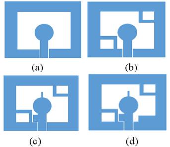
Figure 1: The evolution of CP UWB antenna.
First, we adopts CPW fed circular patch with rectangular slot as the basis. The size of a circular patch can be estimated using the above formula. The introduced two symmetrical rectangular grounds with slot in the diagonal of the square slot help to converge to the 3-dB. The extended orthogonal rectangular branches of the circular can achieve the CP characteristic. And finally rectangular cell in the lower right corner further improves the current distribution to achieve circular polarization in WLAN. Figures 1 (a)–(d) show the iteration process of the antenna.
The original antenna consists of a rectangular slot and circular radiating patch fed by CPW. From Figure 2, we can see clearly that, in the initial design, S below 10 dB ranges from 2.9 to 4.1 GHz, which is far from meeting the impedance bandwidth of UWB. And from Figure 3, we can see that ARBW deteriorates in the whole band, far greater than 3 dB. As shown in Figure 1 (b), although the impedance bandwidth is only expanded to the right by 1 GHz, the overall AR is improved to below 10 dB, when two symmetrical rectangular slot structures in the two opposite corners of every antenna unit is introduced. Further, two orthogonal rectangular branches extend from the top and side of the circular radiator and the impedance bandwidth and 3 dB ARBW are subsequently broaden and enhanced. As illustrated in Figures 2 and 3, the impedance bandwidth is broaden to 8.5 GHz and CP is realized from 4.9 GHz to 5.8 GHz. Finally, a rectangular patch is embedded in lower right of the square slot. S is expanded to 13.5 GHz, from 3.1-13.5 GHz, which fully meets the UWB spectrum. And the AR bandwidth is further improved to cover the entire WLAN band.
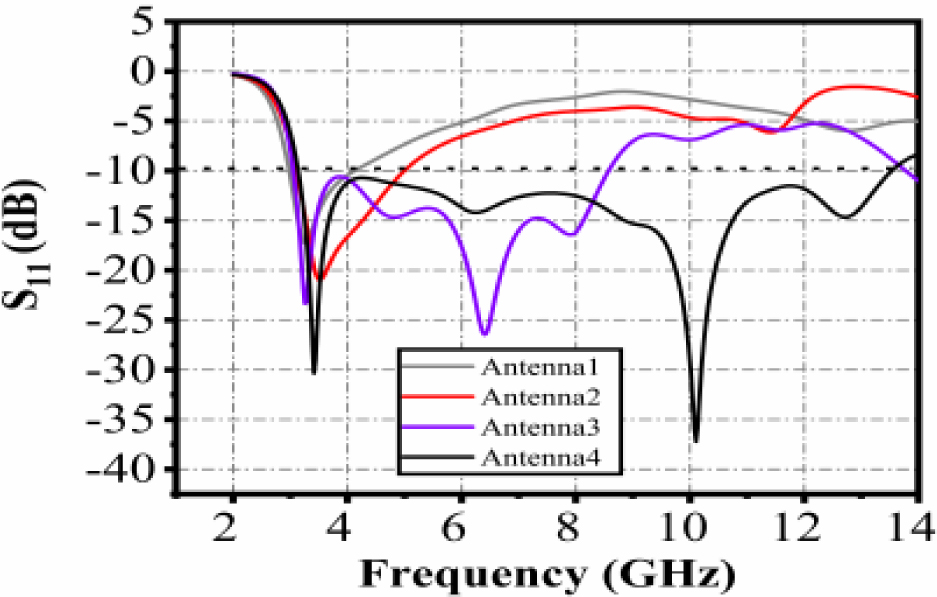
Figure 2: Simulated S.
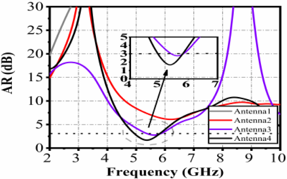
Figure 3: Simulated axial ratio (AR).
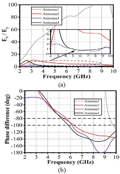
Figure 4: Amplitude ratio and phase difference of the electric field. (a) Amplitude ratio. (b) Phase difference.
To illustrate how the 3 dB ARBW increases with the design process, Figure 4 gives the amplitude ratio and phase difference between the horizontal and vertical components of the electric field in the major axis direction for Ant. 1-Ant. 4, respectively. Ideally, CP waves are generated by exciting two orthogonal modes with equal amplitude and a phase difference of 90. For Ant.1, the amplitude ratio of the two electric field components is much greater than 10 in the entire frequency band, which does not satisfy the circular polarization and also the phase difference does not meet the requirement of 90 degree phase difference. As shown in Figure 4, with the symmetrical rectangular ground with slot in the diagonal of each antenna unit introduced, the amplitude ratio of the antenna drops considerably below 10 throughout the band, and below 5 around 5 GHz, while the phase relationship stabilizes between 80 and 90. As can be seen from Figure 3, the antenna axis ratio has been improved considerably, indicating that the introduced structure can help well in achieving circular polarization characteristics. With the introduction of the extended orthogonal rectangle patch, the amplitude ratio of the antenna is close to 1, showing that the magnitude of the horizontal and vertical components of the electric field antenna are nearly equal at this time. At the same time, the slope of the phase in 4.5-6 GHz is further decreased, resulting in an enhanced axial ratio bandwidth.Finally, the proposed antenna, shown in Figure 3, achieves 3 dB ARBW in 4.9-5.8 GHz with full coverage of the WLAN (5.2-5.8 GHz) band, and the phase difference and amplitude ratio are in accordance with the theoretical excitation of CP.
B Design of MIMO antenna
Based on the CP antenna above, the circularly polarized MIMO UWB antenna is proposed as shown in Figure 5. The dimension of the proposed antenna is 25 51 0.8 mm. The substrate of the proposed antenna is FR4 material with relative permittivity () of 4.4 and loss tangent () of 0.02. And the antenna is fed by coplanar waveguide and connected to a SMA connector with 50 characteristic impedance in the simulation. To enhance the isolation and realize good diversity performance, the slit slot between antenna units and rectangular openings are introduced to achieve high isolation. As illustrated in Figures 6 and 7, S is below 18 dB and 20 dB in the most cases. By introducing the slit slot in the middle of the ground and rectangular openings at the top and bottom of ground to form a defective ground structure, the coupling between the antenna units is reduced to below 15 dB without the need to reserve extra large space. The AR band-width is 4.7-6.1 GHz, completely covering the WLAN band. Thereby, it can work in WLAN band in circular polarization. Meanwhile, impedance band-width also keeps wide (3.1-13.5 GHz). Table 1 shows the specific size parameters of the optimized antenna.
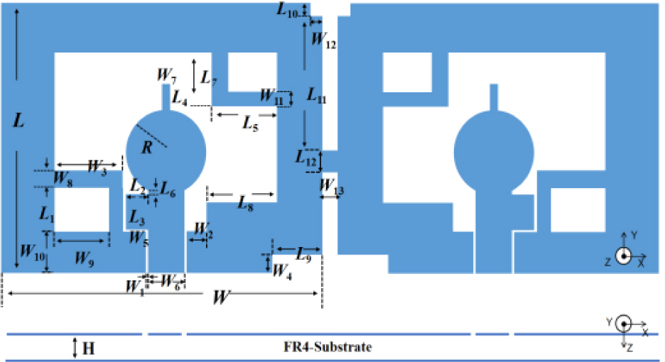
Figure 5: Geometry of circularly polarized UWB MIMO antenna.
Table 1: Dimensions of the proposed antenna (unit: mm)
| Parameter | Size | Parameter | Size |
|---|---|---|---|
| L | 25 | W | 1.2 |
| L | 3.8 | W | 5 |
| L | 2.3 | W | 2 |
| L | 3.4 | W | 0.1 |
| L | 2.7 | W | 3.1 |
| L | 5.5 | W | 0.9 |
| L | 0.7 | W | 1.3 |
| L | 5.5 | W | 4 |
| L | 6 | W | 3.5 |
| L | 4 | W | 1.7 |
| L | 0.9 | W | 0.9 |
| L | 12.1 | W | 1 |
| L | 2 | W | 1.3 |
| W | 25 | H | 0.8 |
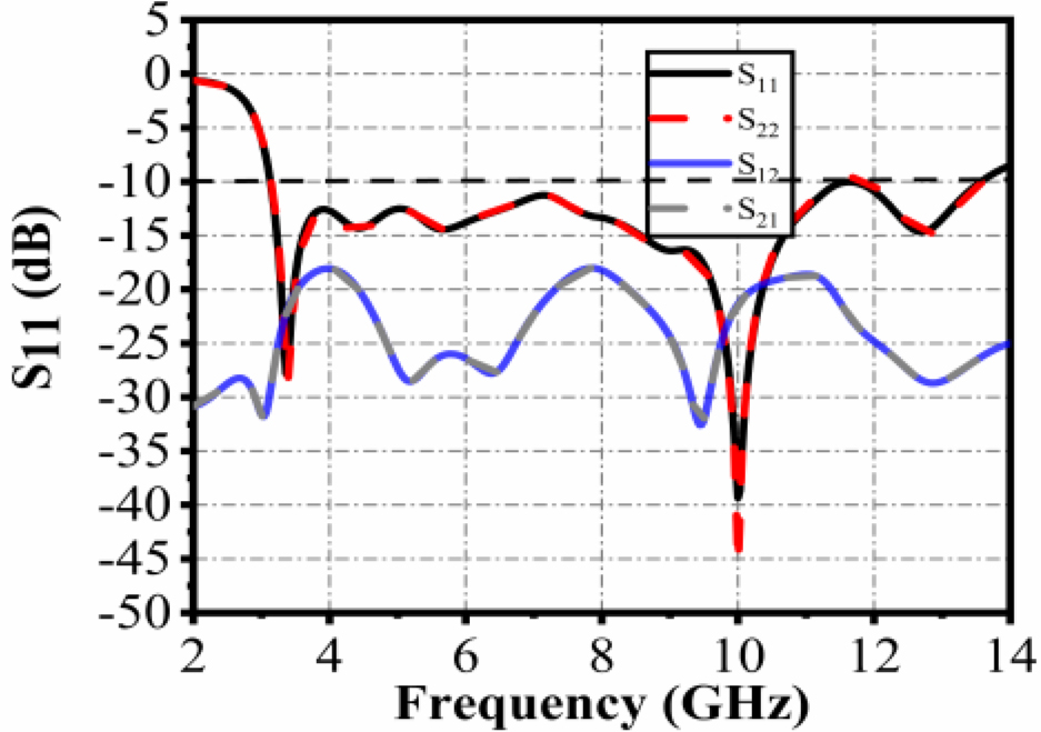
Figure 6: Simulated S-parameter.
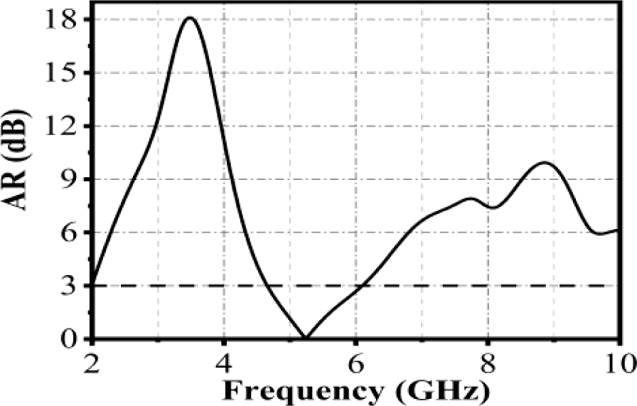
Figure 7: Simulated axial radio (AR).
To illustrate the CP radiation mechanism, the current distribution of the antenna surface is plotted to analyze the generation of polarization. As shown in Figure 8, current distribution of the CP antenna in different phases of 0, 90, 180, and 270 at 5.6 GHz is presented. From Figure 8 (a), we can see that the current flows mainly along the x and y axes, so the direction of the synthetic current vector points to the second quadrant. When the phase is changed by 90, the current direction is along the x and y axes, and the current vector points to the first quadrant, which is orthogonal to the 0 phase direction. Similarly, after changing the phase to 180 and 270, the vector points to the forth and second quadrants in turn. As can be seen from the Figure 8, the current direction rotates in the clockwise direction as phase increases. Thus, the proposed antenna can excite a left-handed circular polarization (LHCP) along the z-axis.
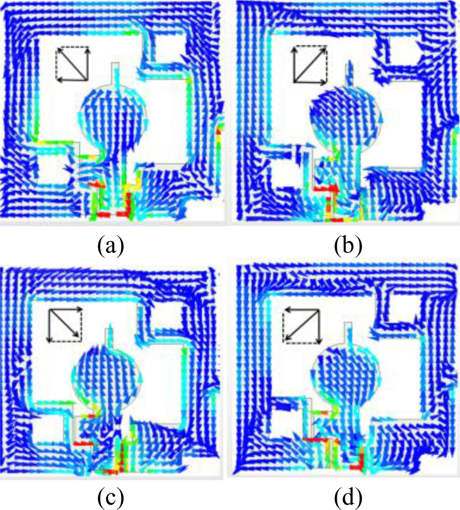
Figure 8: Surface current distributions at 5.6 GHz for four phase angles. (a) 0. (b) 90. (c) 180. (d) 270.
III. PARAMETERS OPTIMIZATION AND DISCUSSION
The width of the symmetrical ground slot, the length of the extended rectangular branch, and the spacing between introduced rectangular branch and circular radiating unit affect the performance of this antenna. So the effect of the variation of these critical parameters on the antenna performance is studied to obtain the optimal results. In the following, the effect of the corresponding structure of the antenna on the 3 dB ARBW and impedance bandwidth is analyzed to achieve better performance of the antenna. In the process of optimizing and analyzing the parameters, we adopt the control variable method, where the other parameters are kept fixed and the relevant variables of interest arechanged.
A The influence of length of side extended rectangular ranch L
Figures 9 (a) and (b) give the effect of the length of the extended rectangular branch on the side of the circular radiating patch (L) on the antenna impedance bandwidth and AR bandwidth, respectively. From Figure 9 (a), it can be seen that L has a large impact on the impedance bandwidth, when L = 0.3 mm, S is almost greater than -10 dB in the entire band, and can not meet the bandwidth of UWB. With the increase of L, the impedance bandwidth is optimized. As shown in Figure 9 (b), the AR bandwidth is greater than 5 dB in 5-6 GHz when L = 0.3 mm. As L increases, CP is achieved and the AR bandwidth is expanded. When L = 1.3 mm, the CP is achieved in 5.4-5.8 GHz, but the impedance bandwidth of 5-7 GHz cannot meet the requirement.
From Figure 9, we can see that the parameter L has a large impact on the performance of the antenna on AR bandwidth and impedance bandwidth. Finally, L is chosen as 2.3 mm as the best value, and the AR bandwidth can cover the WLAN band.
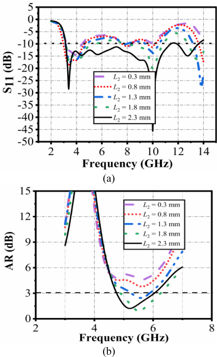
Figure 9: Simulated results of different L. (a) S. (b) AR.
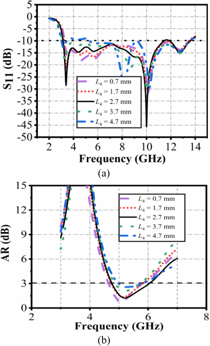
Figure 10: Simulated results of different L. (a) S.(b) AR.
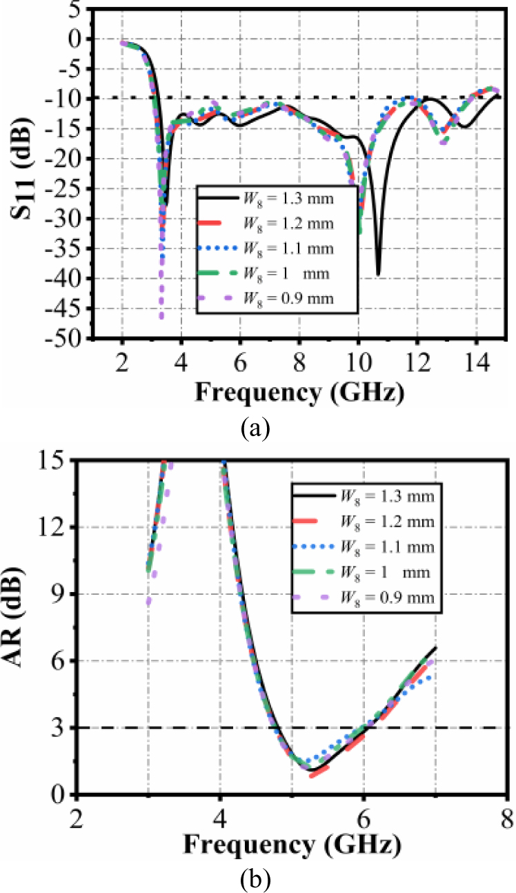
Figure 11: Simulated results of different W. (a) S.(b) AR.
B The influence of length of top extended rectangular branch L
The effect of the top extended rectangular patch on the antenna is further investigated. Fixing other parameters, the effect on the antenna performance is shown below when L is taken to different values. From Figures 10 (a) and (b), it can be seen that when varying L has a small effect on the impedance bandwidth. Only when L= 4.7 mm, S is greater than -10 dB in around 3.7-5 GHz. With increase of L the AR is shifted to the left and bandwidth is broadened. When L = 2.7 mm, the impedance bandwidth is 3.1- 13.5 GHz, with AR bandwidth of 4.6-6.1 GHz.
C The influence of width of rectangular ground with slot W
Figures 11 (a) and (b) show the effect of variation in W on the impedance bandwidth and AR bandwidth. As W increases, the antenna S parameters shift slightly towards the left overall, and covers the entire UWB band. Meanwhile, the AR bandwidth remains almost constant, indicating the AR and impedance bandwidth is not sensitive to the variations of W .
D The influence of length of internal rectangular patch L
The effect of the parameter L on the impedance bandwidth is mainly concentrated in the high frequency band. When L = 3 mm, the impedance bandwidth deteriorates in 10-13 GHz. As L increases, the high frequency band gradually eases, whereas S exceeds -10 dB in 6-10 GHz when L = 7 mm. Although the AR gradually shifts to the left with the increase of L , it can be seen that the effect of this parameter on AR is much less than the effect on the impedance bandwidth. Ultimately, L is chosen as 6 mm.
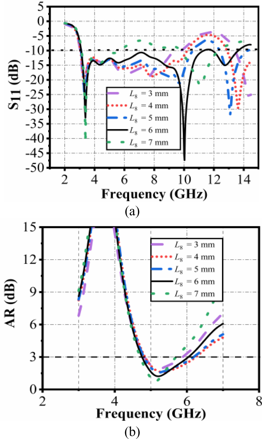
Figure 12: Simulated results of different L. (a) S.(b) AR.
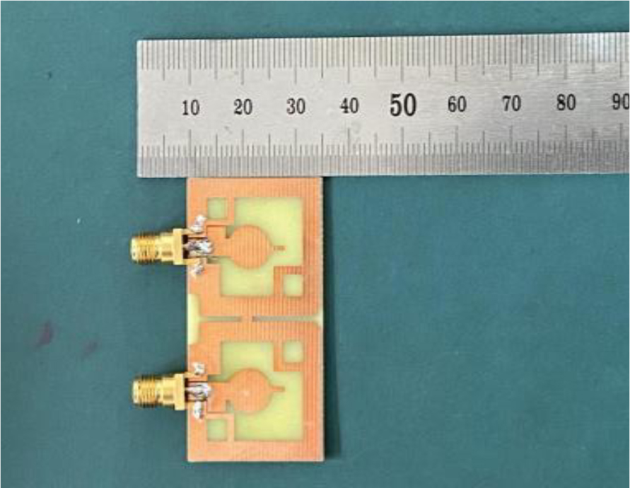
Figure 13: Photograph of the fabricated antenna.
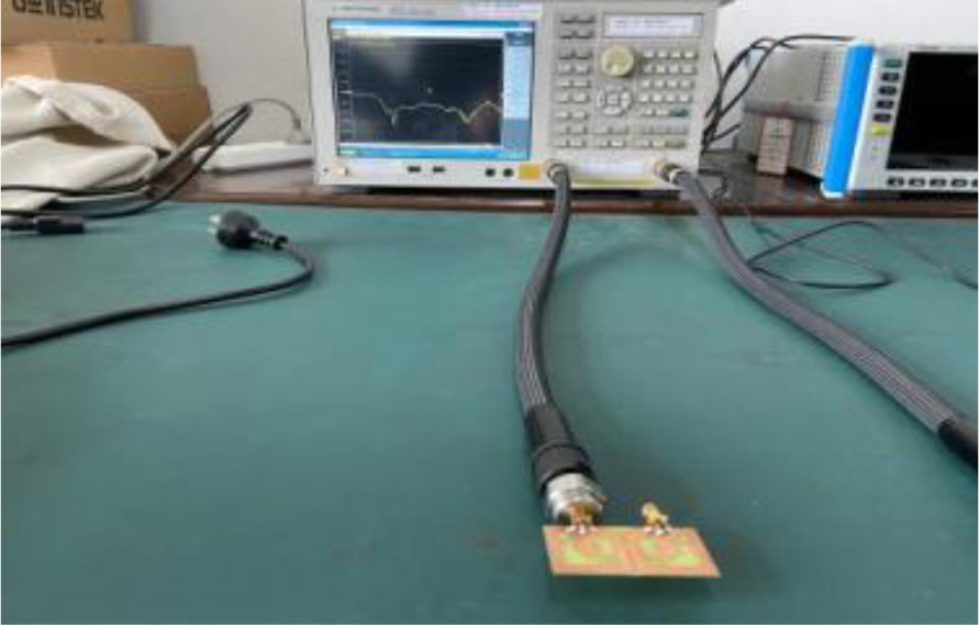
Figure 14: Measured by Agilent NE5071C.
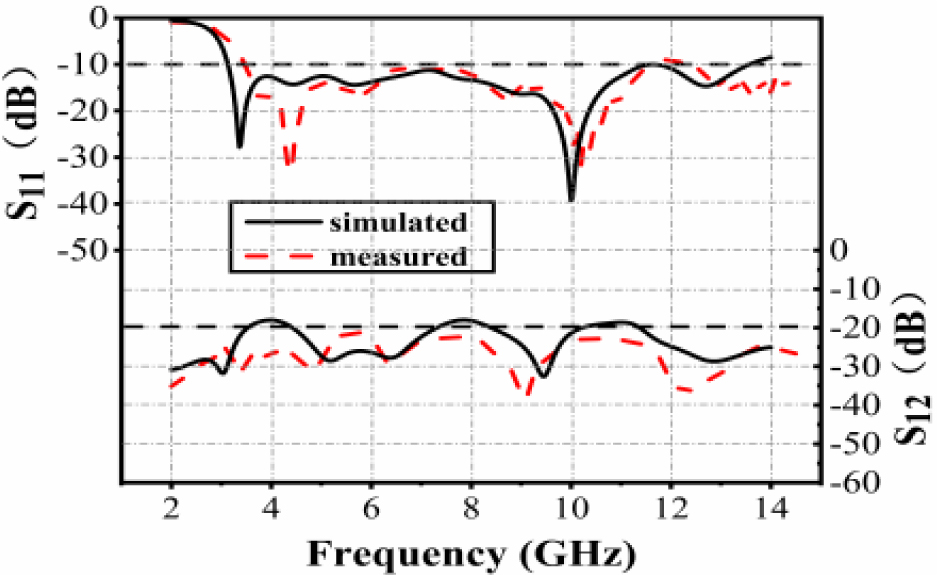
Figure 15: Simulated and measured S-parameter.
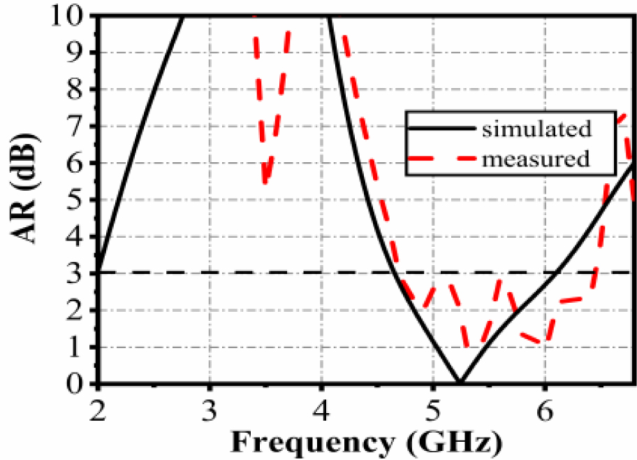
Figure 16: Simulated and measured AR.
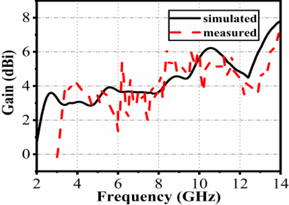
Figure 17: Simulated and measured peak gain.

Figure 18: Measured in SATIMO chamber room.
IV. RESULT AND DISCUSSION
The fabrication of the proposed antenna is shown in Figure 13 with dimensions of 25 51 0.8 mm. The proposed antenna was fabricated on FR4 substrate with dielectric constant of 4.4 and loss tangent of 0.02. The antenna feed line was connected to a 50 SMA. In the test, the scattering parameters were measured by Agilent vector network analyzer NE5071C in Figure 14. And the far-field parameters, like gain, radiation pattern were measured in SATIMO anechoic chamber as shown in Figure 18.
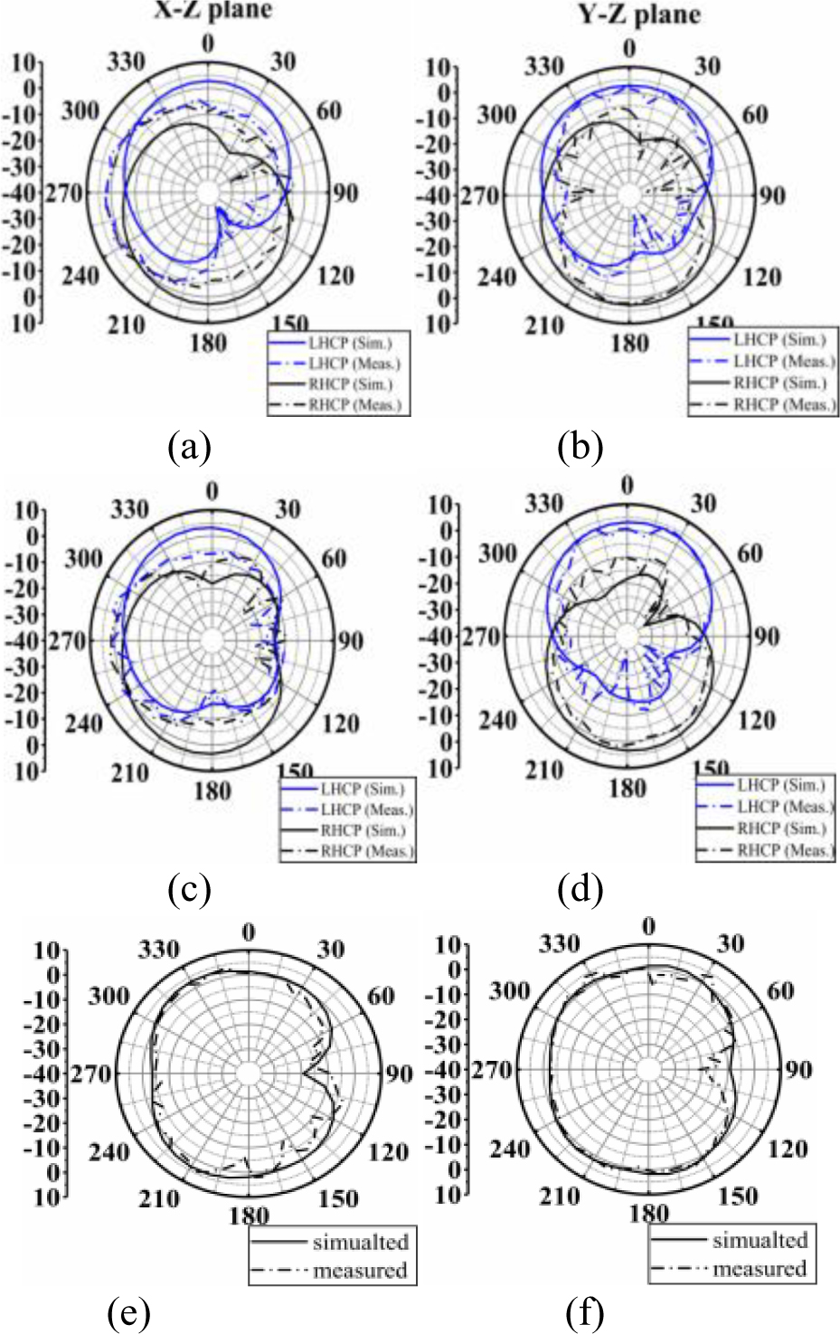
Figure 19: Radiation patterns at different frequencies. (a and b) 4.8 GHz. (c and d) 5.6 GHz. (e and f) 8 GHz.
Table 2: Comparison with related antennas
| Ref. | Overall geometry (mm) | -10 dB IBW (GHz) | 3 dB ARBW (GHz) | Isolation (dB) | ECC | Decouplingmethod |
| [20] | 40 40 1.524 |
3.1-10.6 | linear | -16 | 0.13 | modified ground and orthogonal arrangement |
| [21] | 48 28 1.6 | 3-11.5 | linear | -18 | 0.039 | vertical placement |
| [22] | 50 35 1 | 3-11 | linear | -25 | 0.004 | fence-type decoupling structure |
| [23] | 80 40 1.6 | 2.13-11.03 | linear | -20 | N/A | decoupling stubs |
| [24] | 99.7 33.5 0.8 | 2.9-7.1 | 3.1-6.35 | -20 | 0.003 | extended array element interval |
| [25] | 2525 1.6 | 3-11 | 4-5.5 | -17 | 0.15 | modified ground |
| [26] | 130 130 1 | 1.175-5.79 | 1.75-4.46 | N/A | N/A | N/A |
| [27] | 56 32 3 | 5-6.6 | 5.1-5.85 | -20 | 0.02 | parasitic periodic metallic plates |
| [31] | 32.5 42 1 | 3.6-13 | 5.2-7.1 | -18 | 0.02 | defective ground structure |
| [34] | 150 100 0.8 | 2.5-2.55 | 2.5-2.55 | -20 | 0.003 | decoupling stubs |
| [36] | 35 16 0.8 | 3.1-5 | linear | -22 | N/A | neutralization line |
| [39] | 32 64 1.6 | 3.1-10.6 | linear | -17 | 0.02 | meander-line EBG |
| Proposed | 25 51 0.8 | 3.1-13.5 | 4.7-6.1 | -18 | 0.01 | defective ground structure |
Figure 15 shows the measured S-parameter of the proposed antenna compared with the simulated. It can be seen that, from 3.2 GHz to 13.5 GHz, S is below -10 dB, showing that the impedance bandwidth is more than 10 GHz. Although the starting frequency is slightly shifted to the right, it is acceptable and consistent with simulated results. Figure 16 shows that the measured 3 dB ARBW is 4.7-6.5 GHz, covering the entire WLAN band. And the average peak gain is around 4 dBi as shown in Figure 17. At the same time, in the entire operating band, the MIMO antenna shows good isolation. S reflects the degree of isolation. We can see, in Figure 15, S is below -20 dB in most cases, which shows that the proposed antenna has high isolation. Due to the toleration of manufacturing and welding, there are some deviations between the measured and simulated data.In general, the proposed antenna achieves wide bandwidth and CP as expected.
Figure 19 shows the radiation patterns of the proposed antenna in the X-Z and Y-Z planes, respectively at 4.8 GHz, 5.6GHz, and 8 GHz. As shown in the Figures 19 (a) and 19 (b), the proposed antenna generates LHCP radiation mode in the bore-sight direction. And Figure 19 (c) shows the radiation pattern of the proposed antenna in LP mode and it shows quasi-omnidirectional characteristic. Although there are some discrepancies which may be due to processing errors, measured results is consistent with the analysis results above.
The diversity performance of MIMO antenna can be measured in terms of ECC (envelop correlation coefficient) and DG (diversity gain). ECC is a vital diversityparameter that depicts the correlation or isolation of related channels. ECC can be calculated by considering the impact of all S-parameters. Formula (3) is a quick way to calculate ECC. Usually, ECC below 0.5 is widely adopted criterion for engineering [18].
| (3) |
DG is described as an increment in signal to interference level and can be calculated by formula (4).
| (4) |
As shown in Figure 20, the ECC value of the antenna is less than 0.01 and DG more than 9.95. Hence, the low ECC and high DG indicate that the MIMO antenna has favorable diversity characteristics to combat multipath fading.
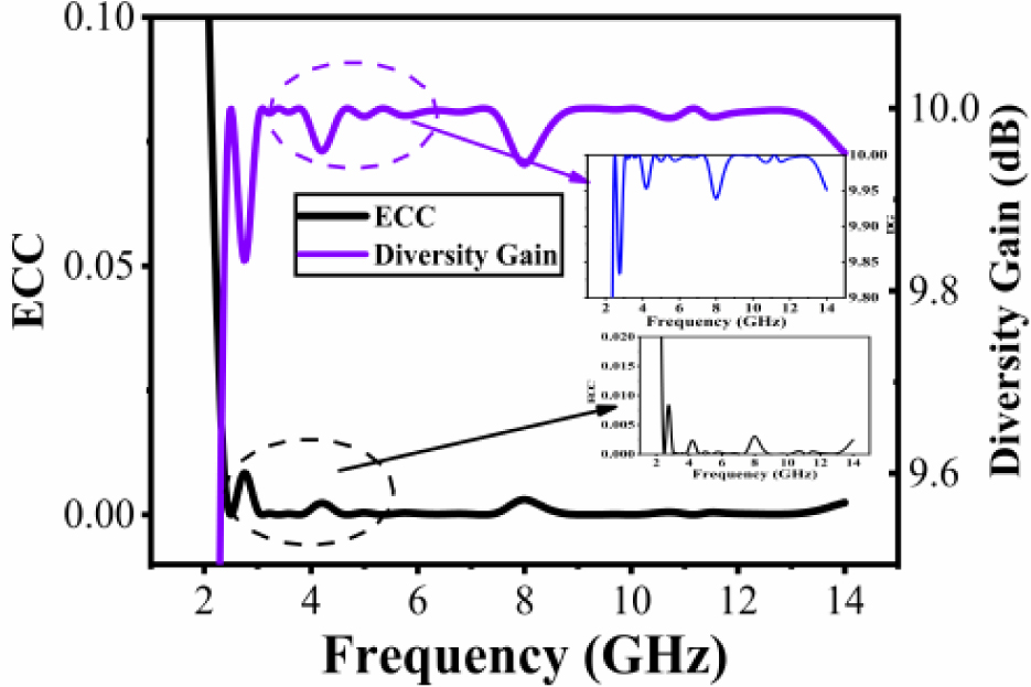
Figure 20: ECC and diversity gain.
Table 2 shows the comparison between the proposed antenna and antennas in the relevant papers. And it can be seen that, the proposed CP antenna has excellent performance parameters with more compact size, larger bandwidth, and high isolation.
V. CONCLUSION
In this paper, we propose a novel compact circularly polarized ultra-wideband MIMO antenna. Compared with common linearly polarized antennas, the proposed antenna can excite CP mode for WLAN communication and its impedance bandwidth can also fully cover UWB spectrum. It has a very compact size and the dimension is 25 51 0.8 mm. The impedance bandwidth is 3.1-13.5 GHz, with average peak gain of 4 dBi, fully covering UWB bandwidth and enhanced by 38%. At the same time, CP is achieved by embedding two symmetrical rectangular slot structures in the two opposite corners of every antenna unit and measured 3 dB ARBW is 4.7-6.5GHz (1.8 GHz), fully covering WLAN band. Meanwhile, the MIMO antenna keeps high isolation, the diversity characteristic ecc is lower than 0.01 and shows very good isolation diversity characteristics. It can simultaneously operate in the UWB spectrum and exhibit CP radiation characteristic in the band of WLAN. Research on how to broaden the AR bandwidth in the entire UWB spectrum is still very difficult. Currently, most can only achieve circular polarization in some frequency bands. And this will be the next step in our work. Overall, the proposed antenna has the advantage of compact size, broadband circularly polarization, enhanced isolation, and easy fabrication.
ACKNOWLEDGMENT
This work was supported by Key Project of the National Natural Science Foundation of China under Grant 62090012, 62031016 and 61831017, the Project under Grant 19-163-21-TS-001-062-01, and the Sichuan Provincial Science and Technology Important Projects under Grant 2019YFG0498, 2020YFG0282, 2020YFG0452 and 2020YFG0028.
REFERENCES
[1] Federal Communication Commission, “First report and order revision of part 15 of the Commission’s rules regarding ultra-wideband transmission system,” Tech. Rep. ET 98-153, FCC, Washington, DC, USA, 2002.
[2] K. S. Ryu and A. A. Kishk, “UWB antenna with single or dual band-notches for lower WLAN band and upper WLAN band,” IEEE Trans. Antennas Propag., vol. 57, no. 12, pp. 3942-3950, 2009.
[3] M. Rahman and J. D. Park, “The smallest form factor UWB antenna with quintuple rejection bands for IoT applications utilizing RSRR and RCSRR,” Sensors, vol. 18, no. 3, p. 911, 2018.
[4] Z. N. Chen, “UWB antennas: From hype, promise to reality,” in Proc. 2007 Loughborough Antennas Propag. Conf., Loughborough, UK, pp. 19-22, 2007.
[5] T. Ali, A. W. Mohammad Saadh, R. C. Biradar, A. Andújar, and J. Anguera, “A miniaturized slotted ground structure UWB antenna for multiband applications,” Microw. Opt. Technol. Lett., vol. 60, pp. 2060-2068, 2018.
[6] J. Y. Siddiqui, C. Saha, and Y. M. M. Antar, “Compact dual-SRR-loaded UWB monopole antenna with dual frequency and wideband notch characteristics,” IEEE Antennas Wirel. Propag. Lett., vol. 14, pp. 100-103, 2015.
[7] K. Kaur, A. Kumar, and N. Sharma, “Split ring slot loaded compact CPW-fed printed monopole antennas for ultra-wideband applications with band notch characteristics,” Progress Electromagn. Res. C, vol. 110, pp. 39-54, 2021.
[8] A. K. Gautam, S. Yadav, and B. K. Kanaujia, “A CPW-fed compact UWB microstrip antenna,” IEEE Antennas Wirel. Propag. Lett., vol. 12, pp. 151-154, 2013.
[9] B. Yang and S. Qu, “A compact integrated Bluetooth UWB dual-band notch antenna for automotive communications,” AEU Int. J. Electronics Commun., vol. 80, pp. 104-113, Oct. 2017.
[10] J. Jan, C. Pan, K. Chiu, and H. Chen, “Broadband CPW-fed circularly-polarized slot antenna with an open slot,” IEEE Trans. Antennas Propag., vol. 61, no. 3, pp. 1418-1422, Mar. 2013.
[11] U. Ullah, S. Koziel, and I. B. Mabrouk, “A simple-topology compact broadband circularly polarized antenna with unidirectional radiation pattern,” IEEE Antennas Wirel. Propag. Lett., vol. 18, no. 12, pp. 2612-2616, Dec. 2019.
[12] S. Zhou, P. Li, Y. Wang, W. Feng, and Z. Liu, “A CPW-fed broadband circularly polarized regular-hexagonal slot antenna with L-shape monopole,” IEEE Antennas Wirel. Propag. Lett., vol. 10, pp. 1182-1185, 2011.
[13] G. Li, H. Zhai, T. Li, L. Li, and C. Liang, “CPW-fed S-shaped slot antenna for broadband circular polarization,” IEEE Antennas Wirel. Propag. Lett., vol. 12, pp. 619-622, 2013.
[14] S. Maddio, “A compact wideband circularly polarized antenna array for C-band applications,” IEEE Antennas Wirel. Propag. Lett., vol. 14, pp. 1081-1084, Dec. 2015.
[15] K. Ding, R. Hong, D. Guan, L. Liu, and Y. Wu, “Broadband circularly polarised stacked antenna with sequential-phase feed technique,” IET Microw. Antennas Propag., vol. 14, pp. 779-784, 2020.
[16] N. Rasool, K. Huang, A. B. Muhammad, and Y. A. Liu, “Wideband circularly polarized slot antenna with antipodal strips for WLAN and C-band applications,” Int. J. RF Microw. Comput. Aided Eng., vol. 29, no. 11, 2019.
[17] J. Wei, X. Jiang, and L. Peng, “Ultrawideband and high-gain circularly polarized antenna with double-Y-shape slot,” IEEE Antennas Wirel. Propag. Lett., vol. 16, pp. 1508-1511, 2017.
[18] C. Luo, J. Hong, and L. Zhong, “Isolation enhancement of a very compact UWB-MIMO slot antenna with two defected ground structures,” IEEE Antennas Wirel. Propag. Lett., vol. 14, pp. 1766-1769, Apr. 2015.
[19] J. Tao and Q. Feng, “Compact ultrawideband MIMO antenna with half-slot structure,” IEEE Antennas Wirel. Propag. Lett., vol. 16, pp. 792-795, 2017.
[20] D. Singh, A. A. Khan, S. A. Naqvi, M. Saeed Khan, A. D. Capobianco, S. Boscolo, M. Midrio, and R. M. Shubair, “Inverted-c ground MIMO antenna for compact UWB applications,” J. Electromagn. Waves Appl., vol. 35, no. 15, pp. 2078-2091, May 2021.
[21] A. A. Ibrahim, J. Machac, and R. M. Shubair, “UWB MIMO antenna for high speed wireless applications,” Applied Computational Electromagnetic Society (ACES) Journal, vol. 34, no. 9, pp. 1294-1299, Sep. 2019.
[22] L. Wang, Z. Du, H. Yang, R. Ma, Y. Zhao, X. Cui, and X. Xi, “Compact UWB MIMO antenna with high isolation using fence-type decoupling structure,” IEEE Antennas Wirel. Propag. Lett., vol. 18, no. 8, pp. 1641-1645, Aug. 2019.
[23] Y. Yu, S. Mao, M. Li, and D. He, “Isolation enhancement between ports of a compact ultra-wideband MIMO antenna,” Applied Computational Electromagnetic Society (ACES) Journal, vol. 36, no. 1, pp. 61-66, Jan. 2021.
[24] U. Ullah, I. B. Mabrouk, S. Koziel, and M. Al-Hasan, “Implementation of spatial/polarization diversity for improved-performance circularly polarized multiple-input-multiple-output ultra-wideband antenna,” IEEE Access, vol. 8, pp. 64112-64119, 2020.
[25] S. Saxena, B. K. Kanaujia, S. Dwari, S. Kumar, and R. Tiwari, “A compact dual-polarized MIMO antenna with distinct diversity performance for UWB applications,” IEEE Antennas Wirel. Propag. Lett., vol. 16, pp. 3096-3099, 2017.
[26] R. Xu, S. S. Gao, J. Liu, J.-Y. Li, Q. Luo, W. Hu, L. Wen, X.-X. Yang, and J. T. Sumantyo, “Analysis and design of ultrawideband circularly polarized antenna and array,” IEEE Trans. Antennas Propag., vol. 68, no. 12, pp. 7842-7853, Dec. 2020.
[27] H. H. Tran, N. Hussain, and T. T. Le, “Low-profile wideband circularly polarized MIMO antenna with polarization diversity for WLAN applications,” AEU-Int. J. Electron. Commun., vol. 108, 2019.
[28] P. Laxman and A. Jain, “Wideband circularly polarised antenna ‘multi-input-multi-output’ for wireless UWB applications,” IET Wireless Sensor Syst., vol. 11, no. 6, pp. 259-274, 2021.
[29] I. Khan, Q. Wu, I. Ullah, S. U. Rahman, H. Ullah, and K. Zhang, “Designed circularly polarized two-port microstrip MIMO antenna for WLAN applications,” Appl. Sci., vol. 12, no. 3,2022.
[30] Jaiverdhan, M. M. Sharma, and R. P. Yadav, “Broadband circularly polarized compact MIMO slot antenna based on strip and stubs for UWB applications,” Electromagnetics, vol. 41, no. 3, pp. 292-302, 2021.
[31] S. Kumar, D. Nandan, K. Srivastava, S. Kumar, H. Singh, M. Marey, H. Mostafa, and B. K. Kanaujia, “Wideband circularly polarized textile MIMO antenna for wearable applications,” IEEE Access, vol. 9, pp. 108601-108613, 2021.
[32] A. Kumar and T. Agrawal, “High performance circularly polarized MIMO antenna with polarization independent metamaterial,” Wirel. Personal Commun., vol. 116, pp. 3205-3216, 2021.
[33] A. Kumar, A. De, and R. K. Jain, “Circular polarized two-element textile antenna with high isolation and polarization diversity for wearable applications,” Int. J. Microw. Wirel. Technol., pp. 1-9, 2022.
[34] M. Y. Jamal, M. Li, and K. L. Yeung, “Isolation enhancement of closely packed dual circularly polarized MIMO antenna using hybrid technique,” IEEE Access, vol. 8, pp. 11241-11247, 2020.
[35] S. Kumar, G. Lee, D. Kim, W. Mohyuddin, H. Choi, and K. Kim, “A compact four-port UWB MIMO antenna with connected ground and wide axial ratio bandwidth,” Int. J. Microw. Wirel. Technol., vol. 12, no. 1, pp. 75-85, 2020.
[36] S. Zhang and G. F. Pedersen, “Mutual coupling reduction for UWB MIMO antennas with a wideband neutralization line,” IEEE Antennas Wirel. Propag. Lett., vol. 15, pp. 166-169, 2016.
[37] U. Ullah, I. B. Mabrouk, and S. Koziel, “Enhanced-performance circularly polarized MIMO antenna with polarization/pattern diversity,” IEEE Access, vol. 8, pp. 11887-11895, 2020.
[38] A. Kumar, A. De, and R. K. Jain., “Novel H-shaped EBG in E-plane for isolation enhancement of compact CPW-fed two-port UWB MIMO antenna,” IETE J. Res., pp. 1-7, 2022.
[39] N. Kumar and K. U. Kiran, “Meander-line electromagnetic bandgap structure for UWB MIMO antenna mutual coupling reduction in E-plane,” Int. J. Electron. Commun., vol. 127, 2020.
BIOGRAPHIES
Lei Zhang was born in Jiangsu, China. He received his B.S. degree in Electronic Information Engi-neering from Yanshan University, Qinghuangdao, China, in 2020. Now, he is pursuing his M.S. degree in Information and Communication Engineering at Southwest Jiaotong University, Chengdu, China. His major research is in miniaturized antenna, RFID technology, ultra-wideband communication, and MIMO technology.

Quanyuan Feng (M’06–SM’08) received the M.S. degree in Micro-electronics and Solid Electronics from the University of Electronic Science and Technology of China, Chengdu, China, in 1991, and the Ph.D. degree in EM Field and Microwave Technology from Southwest Jiaotong University, Chengdu, China, in 2000. He is the Head of Institute of Microelectronics, Southwest Jiaotong University, Chengdu, China. He has been honored as the “Excellent Expert” and the “Leader of Science and Technology” of Sichuan Province owing to his outstanding contribution. To date, more than 500 papers have been published on IEEE Transactions on Antennas and Propagation, IEEE Transactions on Microwave Theory and Techniques, IEEE Antennas and Wireless Propagation Letters, etc., among which more than 300 were registered by SCI and EI. His research interests include integrated circuits design, RFID technology, embedded system, wireless communications, antennas and propagation, microwave & millimeter wave technology, smart information processing, electromagnetic compatibility and RF/ microwave devices & materials, etc.

Muhammad K. Khan has received his BS and Master degree from the COMSATS University Pakistan in 2011 and 2016 respectively. Now he is pursuing his PhD in Information and Communication engineering from Southwest Jiaotong University China. His research interests include electromagnetics and antennas especially in the design and optimization of antenna array, microstrip patch antennas, and ultra wideband antennas.
ACES JOURNAL, Vol. 37, No. 5, 607–618.
doi: 10.13052/2022.ACES.J.370510
© 2021 River Publishers