A Low-profile Wideband PIFA with Co-design of Ground Plane for WLAN Applications
Xiao Yu Li, Zu Ang Liu, and Mei Song Tong
Department of Electronic Science and Technology
Tongji University, Shanghai 201804, China
mstong@tongji.edu.cn
Submitted On: April 24, 2022; Accepted On: February 6, 2023
ABSTRACT
In this paper, a novel low-profile wideband planar inverted-F antenna (PIFA) with co-design of the ground plane for WLAN applications and IoV applications is proposed. This antenna consists of three parts: a slotted radiating patch, a vertical shorting plate and a ground plane with a cross-shaped slot. The influence and the parameter of the slot are discussed. The antenna is fed by a coaxial line and a shorting pin is also used in this design. The overall size of the antenna is mm. The whole structure is simulated in ANSYS Electronics Desktop 2018.0 and several prototypes are made to verify the simulation results. The bandwidth of the antenna can reach GHz ( dB) and cover the frequency range of GHz. The max gain of the antenna is dBi.
Index Terms: low-profile, multi-resonant modes, planar inverted-F antenna, wideband.
I. INTRODUCTION
The planar inverted-F antenna (PIFA) has been widely used in many sub-areas of the modern wireless communication systems because of its high gain and small size, and slots on the radiating patch make it easy to achieve multiband feature. However, due to the single resonant mode, typical PIFA has the disadvantage of a narrow impedance bandwidth, which restricts its application in many wideband-required situations. So, for the PIFA, the enhancement of impedance bandwidth to cover the range of GHz or even more is important for the current communication technology such as 5G wireless applications and 6G wireless systems in the future [1, 2].
A number of papers on the expanding bandwidth of the PIFA have been published. Traditional methods to improve the bandwidth include introducing parasitic patches near the radiating patch [3, 4], enlarging the size of the ground plane [5], and increasing the height of the whole structure. In [3], a vertical parasitic element is loaded and the impedance bandwidth is enhanced to about 48%, while the overall size is increased and the fabrication becomes more difficult. In [6], the influence of the ground plane on the impedance bandwidth is studied and then four different PIFA designs are evaluated. The results show that altering the slots on the ground plane can effectively change the bandwidth and the slots must be perpendicular to the dominant current direction, which provides some design guides in this paper.
Furthermore, adjusting the resonant frequencies to combine the bandwidth of two or more resonant frequencies has become a prevalent method in recent years. By combining TM and TM modes, the bandwidth of the antenna in [7] increases to about . In [8], the bandwidth increases to through a similar method. A pair of shorting pins are loaded and a slot is etched in [9], and TM and TM modes are combined. The bandwidth increased to and could meet the requirements for 5G WLAN applications. In [10], a small rectangular strip is loaded on the top of the feeding probe and TM and TM modes are combined, and the impedance bandwidth is enhanced to about 33% (from to GHz). However, the position of the strip might bring challenges for the fabrication, and the height of the substrate (0.254 mm) is hard to control during manufacturing.
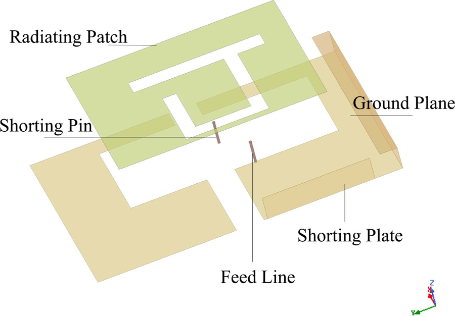
Figure 1: Components of the proposed antenna.
In this paper, a novel low-profile wideband planar inverted-F antenna with co-design of the ground plane is proposed as shown in Fig. 1. The design process is introduced and some important parameters are studied. A cross-shaped slot is loaded on the ground plane and the size and position of the slot are studied to enhance the impedance bandwidth. The results show that the slot that parallels to the dominant current direction on the ground plane can change the bandwidth of the antenna effectively. The data from the simulation and the measurement of the proposed antenna show that the bandwidth ( dB) can be expanded to , covering the range of GHz to GHz. The max gain can be dBi and the vertical omnidirectional performance is also better than typical PIFAs.
II. GEOMETRY AND FABRICATION
The proposed antenna is shown in Fig. 2, consisting of a radiating patch, a shorting plate, a ground plane, a shorting pin and a coaxial feed line. The slot on the radiating patch is designed to excite multiple radiation modes. The positions of the shorting pin and the feed point are well-chosen to realize the wideband feature, and the details will be shown in the next section. The ground plane is etched with a cross-shaped slot to combine the radiation modes and the influence of the width is studied. The values of the design properties are shown in Table 1. The entire structure is simulated using ANSYS Electronic Desktop 2018.0.

Figure 2: Design parameters of components. (a) Patch. (b) Shorting plate. (c) Ground plane.
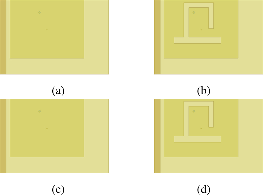
Figure 3: Design process. (a) Original PIFA. (b) Slot on the patch. (c) Slot on the ground plane. (d) Wide slot.
Table 1: Design parameters
| Parameters | Dimension | Parameters | Dimension | Parameters | Dimension |
|---|---|---|---|---|---|
| 23.5 mm | 5 mm | 4 mm | |||
| 10.5 mm | 30 mm | 20 mm | |||
| 14 mm | 19 mm | 16 mm | |||
| 2.5 mm | 12 mm | 19 mm | |||
| 30 mm | 2 mm | 15.5 mm | |||
| 14 mm | 44 mm | 3.5 mm | |||
| 13 mm | 30 mm |
III. DESIGN APPROACH AND PARAMETRIC STUDIES
A. Design approach
Figure 3 shows the design approach of the proposed antenna. In Fig. 3 (a), a traditional single mode PIFA with narrow bandwidth is shown and its resonant frequency is GHz. A winding slot similar to U-shape is loaded in Fig. 3 (b) to excite multiple resonant frequencies. The antenna becomes a tri-band PIFA with the slot. The basic principle for the expanding of bandwidth is to pull these resonant frequencies closer and combine those receptive frequency ranges. In Fig. 3 (c), a narrow slot parallel to x-axis on the ground plane is loaded to widen the bandwidth of each frequencies. Finally, a wide slot vertical to the narrow one is loaded to combine these resonant frequencies further as shown in Fig. 3 (d) and the effect will be discussed later. The positions of the feed point and shorting pin are well-chosen to achieve a better bandwidth, and the sizes of the patch and the ground plane have been adjusted during the design process.
B. Parametric studies
In the PIFA, the relative position between feed point and slot can effectively change the radiating performance. Usually, etching a winding slot between the feed point may excite more than one radiating mode and alter the current distribution on the patch. Hence, the parameter is important for the whole radiating feature. Figure 4 shows the results of different values of , and it can be seen that as the value increases, the impedance bandwidth ( dB) decreases significantly and the shape of the curve becomes sharper. This can be attributed to the difference between the two resonant frequencies decreasing as the value of increases. The value of is chosen to be mm to reach a better bandwidth performance.
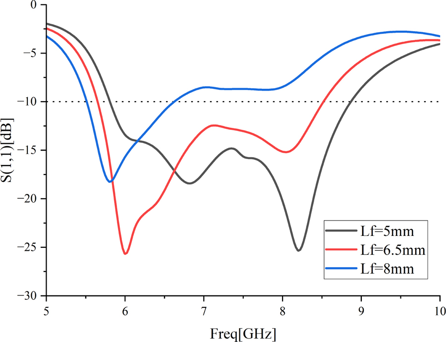
Figure 4: The influence of .
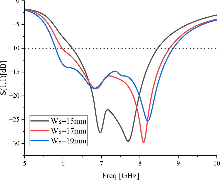
Figure 5: The influence of .
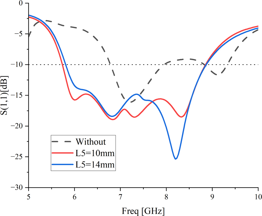
Figure 6: The influence of .
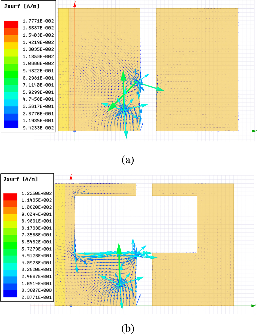
Figure 7: Current density on the ground plane. (a) Without the wide slot. (b) With the wide slot.
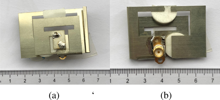
Figure 8: Prototype of the proposed antenna. (a) Top view. (b) Bottom view.
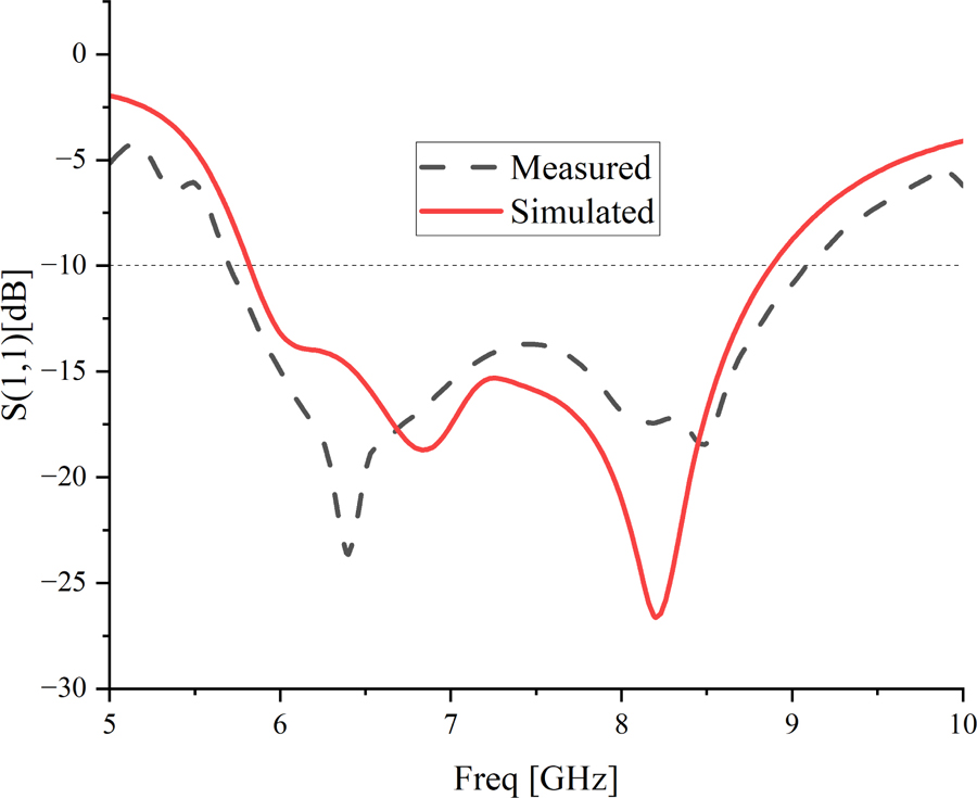
Figure 9: Return loss of simulation and measurements.
Additionally, the influence of the shorting pin’s position is also studied. The results are shown in Fig. 5. Moving the shorting pin does not change the whole radiating performance as significantly as the feed point. The impedance bandwidth decreases slightly as the value of decreases, while the magnitude of return loss increases. In this case, mm is chosen to expand the dB range further.
The design of the ground plane is a convenient way to improve the radiating performance without adding extra components and complicating the whole structure. According to [6], it is found that altering the ground plane using slots can allow for greater bandwidth and the direction of the slots must be perpendicular to the predominant current direction. For the proposed antenna, a perpendicular slot is used on the ground plane. In addition, a wide vertical slot is added and a cross-shaped slot is made. Figure 6 shows the influence of the wide slot and the radiating performance is improved after adding it. The width of the wide slot is chosen to be mm. Figure 7 shows the current flow distribution on the ground plane with and without the wide slot. It can be seen that the slot does not change the main current concentration points, but the current density does become larger in the slot edge area.
IV. RESULTS AND DISCUSSION
The prototypes of the antenna are fabricated and measured, in order to verify the results of simulation. A vector network analyzer is used to measure the return loss, and the far-field antenna test system is used to measure the radiation patterns. The pictures of the prototype are shown in Fig. 8, including top and bottomviews.
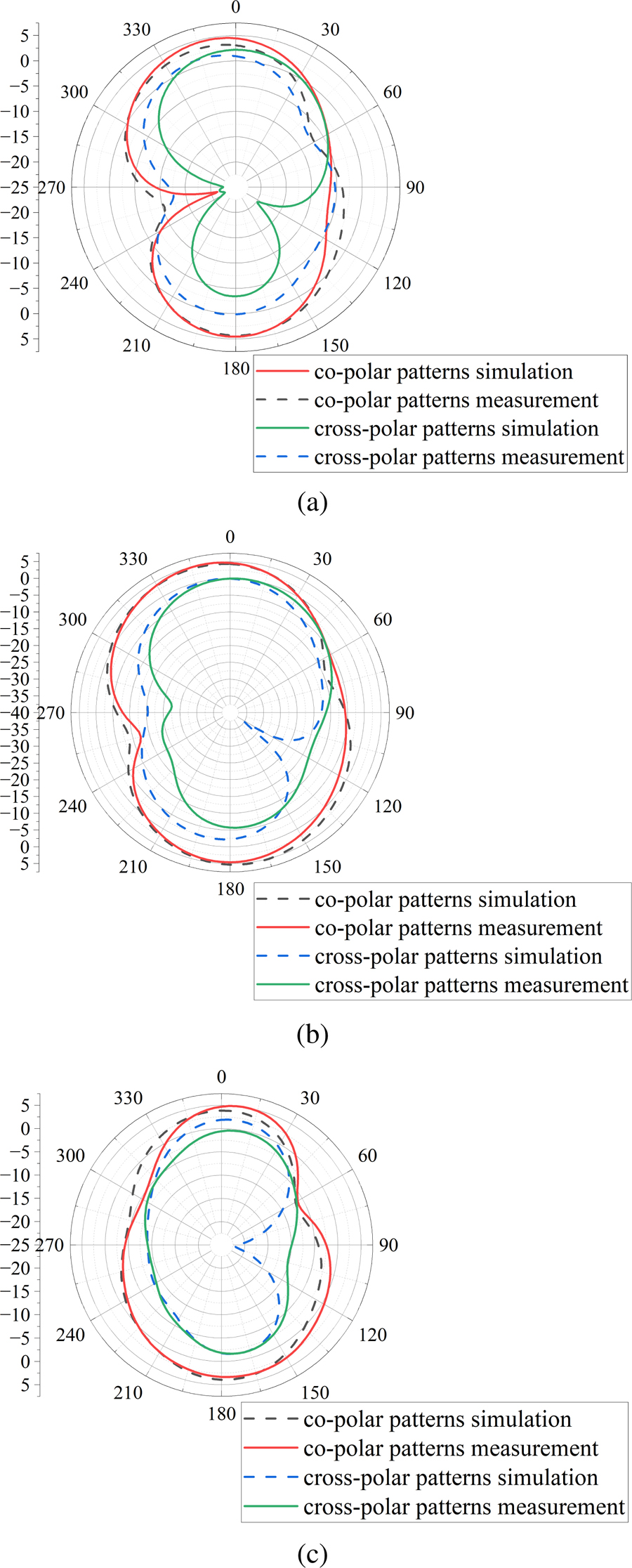
Figure 10: Radiation patterns at GHz, GHz, and GHz on the plane. (a) 5.89 GHz. (b) 6.56 GHz. (c) 8.14 GHz.
A. Return loss
The simulated and measured results of return loss are shown in Fig. 9. For simulated results, the impedance bandwidth ( dB) covers the range of GHz to GHz, and the fractional bandwidth is . For measured results, GHz is covered, and the total bandwidth is GHz with a fractional bandwidth of . It can be concluded that the results of the simulation and the measurement are in quite good agreement. The results of different prototypes are not the same due to fabrication errors, and a position deviation of only mm of the feed point may cause a huge difference in results, as shown in the parameter studies section. The proposed antenna can meet the requirement of 5G and 6G WLAN. The bandwidth has been expanded several times compared to thetraditional PIFA.
B. Radiation patterns
The radiation pattern of the proposed antenna is shown in Fig. 10. The gains at GHz, GHz, and GHz on the plane are measured and the peak gain is dBi, obtained at GHz according to measurement. At high resonant frequency points, the radiation patterns are approximately omnidirectional and the minima of gain is more than dBi, which achieves a better vertical omnidirectional performance compared to traditional PIFAs. That might be attributed to the folded ground plane and is about to study in the future.
C. Peak gain and efficiency
The gain and simulated efficiency are shown in Fig. 11. The results show that the peak gain of the proposed antenna remains stable in this wide bandwidth. The simulated efficiency remains about in the entire frequency range.
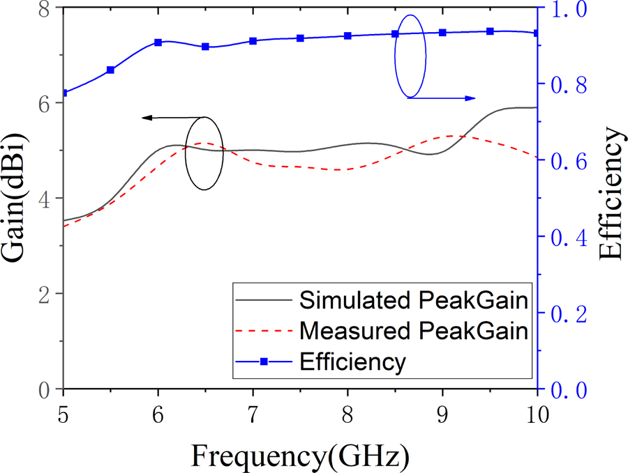
Figure 11: Gain and efficiency.
Table 2: Comparisons of the proposed antenna to other PIFAs
| Ref. | Area (mm) | Profile (mm) | (GHz) | BW (GHz) | Peak Gain (dBi) | Size Comparison |
|---|---|---|---|---|---|---|
| [9] | 4636 | 5.5 | 5.5 | 0.94(18%) | 5.90 | 197.1% |
| [10] | 5341.4 | 1.754 | 6 | 2(33.33%) | 10.82 | 83.3% |
| [11] | 4228 | 4 | 5.5 | 0.94(17.09%) | 6.70 | 101.8% |
| This work | 4430 | 3.5 | 7.62 | 3.96(51%) | 5.40 | 100% |
V. CONCLUSION
A low-profile wideband planar inverted-F antenna is proposed in this paper. A cross-shaped slot is used on the ground plane to combine three resonant modes and achieve the wide bandwidth feature. Several prototypes are fabricated to verify the simulation results. The proposed antenna has a measured dB bandwidth of GHz and the fractional bandwidth is . A peak gain of dBi is measured and the gain remains stable in the bandwidth. The proposed antenna can meet the requirements for wireless local area networks ( MHz), and IoV applications ( MHz). The latest 6G-band of WiFi 6E ( MHz) is also covered. The comparisons between the proposed antenna and other PIFAs are shown in Table 2.
ACKNOWLEDGEMENTS
This work was supported by the National Natural Science Foundation of China with the Project No. 62071331.
REFERENCES
[1] Y. Zhang, L. Gao, and X. Y. Zhang, “Compact quad-band bandpass filter for DCS/WLAN/WiMAX/5G Wi-Fi application,” IEEE Microw. Wirel. Components Lett., vol. 25, no. 10, pp. 645-647, Oct. 2015.
[2] N. H. Mahmood, H. Alves, O. A. López, M. Shehab, D. P. M. Osorio, and M. Latva-Aho, “Six key features of machine type communication in 6G,” 2020 2nd 6G Wireless Summit, Levi, Finland, Mar. 2020.
[3] K. L. Lau, P. Li, and K. M. Luk, “A wideband and dual-frequency shorted-patch antenna with compact size,” IEEE Antennas and Propagation Society Symposium, vol. 1, pp. 249-252, Monterey, CA, Jul. 2004.
[4] S. J. Lin and J. S. Row, “Bandwidth enhancement for dual-frequency microstrip antenna with conical radiation,” Electron. Lett., vol. 44, no. 1, pp. 2–3, Feb. 2008.
[5] M. C. Huynhand and W. Stutzman, “Ground plane effects on planar inverted-F antenna (PIFA) performance,” IEE Proc. Microw. Antennas Propag., vol. 150, no. 4, pp. 209–213, Aug. 2003.
[6] N. L. Bohannon and J. T. Bernhard, “Design guidelines using characteristic mode theory for improving the bandwidth of PIFAs,” IEEE Trans. Antennas Propag., vol. 63, no. 2, pp. 459-465, Feb. 2015.
[7] N. Liu, L. Zhu, W. Choi, and X. Zhang, “A low-profile differential-fed patch antenna with bandwidth enhancement and sidelobe reduction under operation of TM and TM modes,” IEEE Trans. Antennas Propag., vol. 66, no. 9, pp. 4854–4859, Sep. 2018.
[8] N. W. Liu, L. Zhu, W. W. Choi, and X. Zhang, “Wideband shorted patch antenna under radiation of dual-resonant modes,” IEEE Trans. Antennas Propag., vol. 65, no. 6, pp. 2789–2796, Jun. 2017.
[9] G. Gao, C. Yang, B. Hu, R. Zhang, and S. Wang, “A wide-bandwidth wearable all-textile PIFA with dual resonance modes for 5GHz WLAN applications,” IEEE Trans. Antennas Propag., vol. 67, no. 6, pp. 4206–4211, Jun. 2019.
[10] R. Jian, Y. Chen, and T. Chen, “A low-profile wideband PIFA based on radiation of multiresonant modes,” IEEE Antennas Wirel. Propag. Lett., vol. 19, no. 4, pp. 685-689, Apr. 2020.
[11] G. Gao, C. Yang, B. Hu, R. Zhang, and S. Wang, “A wearable PIFA with an all-textile metasurface for 5 GHz WBAN applications,” IEEE Antennas Wirel. Propag. Lett., vol. 18, no. 2, pp. 288-292, Feb. 2019.
BIOGRAPHIES

Xiao Yu Li received the B.S. degree in Communication and Information Engineering and the M.S. degree in Electronic and Information Engineering from University of Electronic Science and Technology of China, Chengdu, China, in 2017 and 2020, respectively. He is currently pursuing the Ph.D. degree in Control Science and Engineering with Tongji University, Shanghai, China, and his current research interests include reconfigurable antennas and computational electromagnetics.

Zu Ang Liu received the B.S. degree of Electronic Science and Technology and the M.S. degree of Microelectronic Science and Engineering from Tongji University, Shanghai, China, in July 2019 and June 2022, respectively. Currently, he is an engineer in a high-tech company, Beijing, China.

Mei Song Tong received the B.S. and M.S. Degrees from Huazhong University of Science and Technology, Wuhan, China, respectively, and Ph.D. degree from Arizona State University, Tempe, Arizona, USA, all in electrical engineering. Currently, he is the Distinguished/Permanent Professor, Head of Department of Electronic Science and Technology, and Vice Dean of College of Microelectronics, Tongji University, Shanghai, China. He has also held an adjunct professorship at the University of Illinois at Urbana-Champaign, Urbana, Illinois, USA, and an honorary professorship at the University of Hong Kong, Hong Kong, China. He has published more than 500 papers in refereed journals and conference proceedings and co-authored six books or book chapters. His research interests include electromagnetic field theory, antenna theory and technique, modeling and simulation of RF/microwave circuits and devices, interconnect and packaging analysis, inverse electromagnetic scattering for imaging, and computational electromagnetics.
Prof. Tong is a Fellow of the Electromagnetics Academy, Fellow of the Japan Society for the Promotion of Science (JSPS), and Full Member (Commission B) of the USNC/URSI. He has been the chair of Shanghai Chapter since 2014 and the chair of SIGHT committee in 2018, respectively, in IEEE Antennas and Propagation Society. He has served as an associate editor or guest editor for some well-known international journals, including IEEE Antennas and Propagation Magazine, IEEE Transactions on Antennas and Propagation, IEEE Transactions on Components, Packaging and Manufacturing Technology, International Journal of Numerical Modeling: Electronic Networks, Devices and Fields, Progress in Electromagnetics Research, and Journal of Electromagnetic Waves and Applications, etc. He also frequently served as a session organizer/chair, technical program committee member/chair, and general chair for some prestigious international conferences. He was the recipient of a Visiting Professorship Award from Kyoto University, Japan, in 2012, and from University of Hong Kong, China, 2013. He advised and coauthored 12 papers that received the Best Student Paper Award from different international conferences. He was the recipient of the Travel Fellowship Award of USNC/URSI for the 31th General Assembly and Scientific Symposium (GASS) in 2014, Advance Award of Science and Technology of Shanghai Municipal Government in 2015, Fellowship Award of JSPS in 2016, Innovation Award of Universities’ Achievements of Ministry of Education of China in 2017, Innovation Achievement Award of Industry-Academia-Research Collaboration of China in 2019, Chapters Award of IEEE New Jersey Section, USA, in 2019, “Jinqiao” Award of Technology Market Association of China in 2020, and Baosteel Education Award of China in 2021. In 2018, he was selected as the Distinguished Lecturer (DL) of IEEE Antennas and Propagation Society for 2019-2022.
ACES JOURNAL, Vol. 38, No. 2, 148–153
doi: 10.13052/2023.ACES.J.380209
© 2023 River Publishers