Low-RCS Surface Design Based on Lossy Metagratings
Kai Wang, Wei Shao, Hua Li, and Bing-Zhong Wang
1School of Physics, University of Electronic Science and Technology of China, Chengdu 611731, China
wkaiuestc2016@163.com, weishao@uestc.edu.cn, lihua2006@uestc.edu.cn, bzwang@uestc.edu.cn
Submitted On: July 1, 2020; Accepted On: March 10, 2022
Abstract
A design method based on the lossy metagrating for radar cross section (RCS) reduction is proposed in this paper. According to the mechanism of the RCS reduction, the lossy metagrating with different loaded lines per supercell is studied and it is also incorporated into the metasurface to reduce RCS. The embedded metagrating provides an additional low-RCS band and it has a small effect on the original band of the metasurface. Numerical results show that the metagrating reduces RCS of the surface effectively.
Keywords: Diffraction pattern, lossy metagrating, low-RCS, metasurface.
I. INTRODUCTION
Metasurfaces have been used for the reduction of the radar cross section (RCS) of target objects [1–4]. The fundamental mechanisms of a metasurface for RCS reduction are absorption and scattering control of electromagnetic waves [5]. The methods used for the analysis of a metasurface, such as the equivalent circuit method and transmission matrix method, take the metasurface as an impedance surface [6]. The size of the element of the metasurface and the separation distances between the elements are in the scale of subwavelength. Thus, it is costly to apply tunable and lumped elements to the metasurface.
Metagratings are proposed for the perfect anomalous reflection and then extended for controlling the diffraction pattern [7–10]. A loss-free metagrating provides an effective way to control the diffracted plane waves. The separation distance between two neighboring lines in a metagrating is bigger than half of the vacuum wavelength and the surface impedance is not available for calculation. The metagrating has the smaller number of lines than the metasurface with the same size and working frequency [7, 11]. So, the metagrating requires fewer lumped elements than the metasurface on a similar occasion.
In this paper, the lossy metagratings are designed to reduce RCS when they cover the target objects. Resistors are loaded to a loss-free metagrating, and the obtained lossy one, as far as we know, has not been studied for RCS reduction. A uniform metagrating loaded with the resistors, which consists of only one line per element, is first studied on its electromagnetic properties. The lossy metagrating provides a frequency band to absorb the incident plane wave while the loss-free metagrating cannot absorb the wave. Second, a lossy metagrating including five lines per supercell is also designed. By diffusing the diffracted plane waves, the RCS of the surface is reduced effectively. The lossy metagrating shows its lower reflection results than the loss-free one. Finally, the lossy metagrating that produces an extra absorbing band is incorporated into the low-RCS metasurface to obtain the better absorbing ability.
II. LOW-RCS METAGRATING
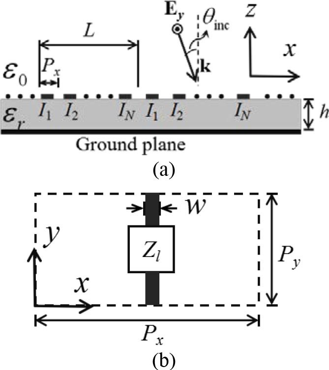
Figure 1: Metagrating on a grounded dielectric substrate. (a) Metagrating. (b) An element in the supercell.
A two-dimensional () metagrating that is printed on a grounded dielectric substrate and is composed of a quantity of conducting lines is shown in Figure 1. The lines are along the y-direction, the separation distance between two neighboring lines is P, and the thickness of the substrate is h. Each line is loaded by an impedance of Z alone the y-direction and it is considered as a uniform impedance line with Z = Z/P. The impedances are loaded with a periodicity of N; so N lines form a supercell with a length of L = NP. The metagrating is excited by a transverse electric (TE) polarized plane wave at an angle of . Due to the presentation of the grounded substrate, the reflected plane wave will be also taken as the excitation.
From the Floquet-Bloch (FB) theory, the induced current on the line in the mth supercell is defined as
| (1) |
where is the Dirac function, , I is the induced current of the nth line in a supercell, and k is the vacuum wavenumber. The diffraction waves are produced by the excitation and the induced currents on the lines. The induced currents are determined by the excitation and the loaded impedance. The radiation pattern of the metagrating is available when the excitation and loaded impedance are known. After the design of the loaded impedance of the metagrating, the diffraction patterns can be controlled. The designed loaded impedances are realized with the distributed parameters and lumped resistors.
The transverse and longitudinal wavenumbers of the qth diffracted plane wave are calculated by = ksin() + 2q/L and , respectively. When || k, the qth diffracted plane wave is propagating. The diffracted wave is evanescent when || k and proper is taken. The magnitudes of the electric field of the incident wave and qth reflected plane wave are denoted as and , respectively. We denote
A. Lossy metagrating with only one loaded line per supercell
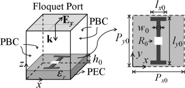
Figure 2: Supercell of the uniform lossy metagrating, where P= 42 mm, P= 12 mm, h= 5 mm, w= 1 mm, l= 1.2 mm, l= 11 mm, and R= 26 .
The lossy component is not involved in the metagrating above. The lossy metagrating can be realized by taking Z as a complex number and the corresponding equations about the current and impedance still work well. We design a low-RCS metagrating working at f= 5GHz and there is only one loaded line in a supercell. Z is designed so that the normally incident plane wave is absorbed by the metagrating. The size and the loaded resistor of the supercell are calculated by Z. The metagrating, in this paper, is designed based on the theory where the incident wave is the TE wave.
A supercell of the designed metagrating is shown in Figure 2, where the black part is the perfect electric conductor (PEC) with a thickness of 0.035 mm and the white part is the loaded lumped resistor. It is surrounded by the periodic boundary condition (PBC) and excited by a normally incident plane wave. The relative permittivity of the dielectric substrate in this paper is = 4.4(1 + 0.02j). P is bigger than 0.5, where is the vacuum wavelength at the frequency of f.
The performance of the lossy metagrating is shown in Figure 3. For = 0 and = 45, we get P = {0} and P = {1, 0}, respectively. The magnitudes of the reflected wave are shown in Figure 3(a) when = 0 and = 45. The relative bandwidth with || 10 dB is about 10% when = 0. There are two diffracted propagating plane waves when = 45, || 5 dB, and || 5 dB at 5 GHz. Some power is absorbed by the lossy metagrating and the absorption rate is defined as
| (2) |
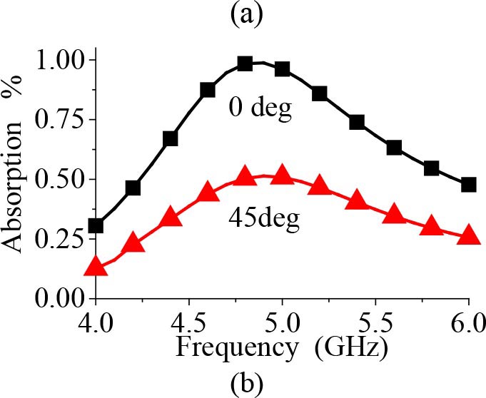
Figure 3: Radiation performance of the uniform lossy metagrating. (a) Reflection. (b) Absorption.
From Figure 3(b), the incident power is mainly absorbed by the metagrating when = 0 and f= 5 GHz. Half of the power is reflected by the metagrating when = 45 and f= 5 GHz. The substrate also loses some of the incident power. The resistance of the loaded resistor of the metagrating is much smaller than that of a metasurface absorber. The fundamental mechanisms of the low-RCS metagrating are absorption when = 0 and absorption and scattering control when = 45.
B. Lossy metagrating with five loaded lines per supercell
The metagrating with multiple loaded lines in a supercell is studied and the metagrating with five loaded lines per supercell is taken as an example. Both loss-free and lossy metagratings are studied here. The loaded reactance of the loss-free metagrating is designed so that the reflected propagating waves have an equal amplitude with a normally incident plane wave. The sizes of the elements are determined by the method proposed in [9]. The lossy metagrating takes the same geometry of the element as the loss-free one and uses the optimized lumped resistors so that all the reflected waves are suppressed. Both the loss-free and lossy metagratings are symmetrical and only three elements are needed to be designed.
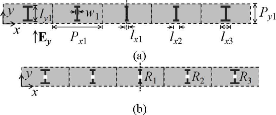
Figure 4: Metagrating with multiple elements. (a) Loss-free metagrating. (b) Lossy metagrating. P= 30 mm, P= 12 mm, l= 11 mm, w= 1 mm, l= 1 mm, l= 2.2 mm, l= 3 mm, R= 15 , R=25 , and R= 45 .
The geometry of the designed metagratings is shown in Figure 4. Here, P = 0.5 at f= 5 GHz and the thickness of the substrate is 5 mm.
The diffracted performance of the metagratings is shown in Figure 5. We provide only the results of three plane waves due to the symmetry of the structures. The reflected waves have an equal amplitude at 5 GHz for the loss-free metagrating and there is a bandwidth of 20% with || 5 dB for q
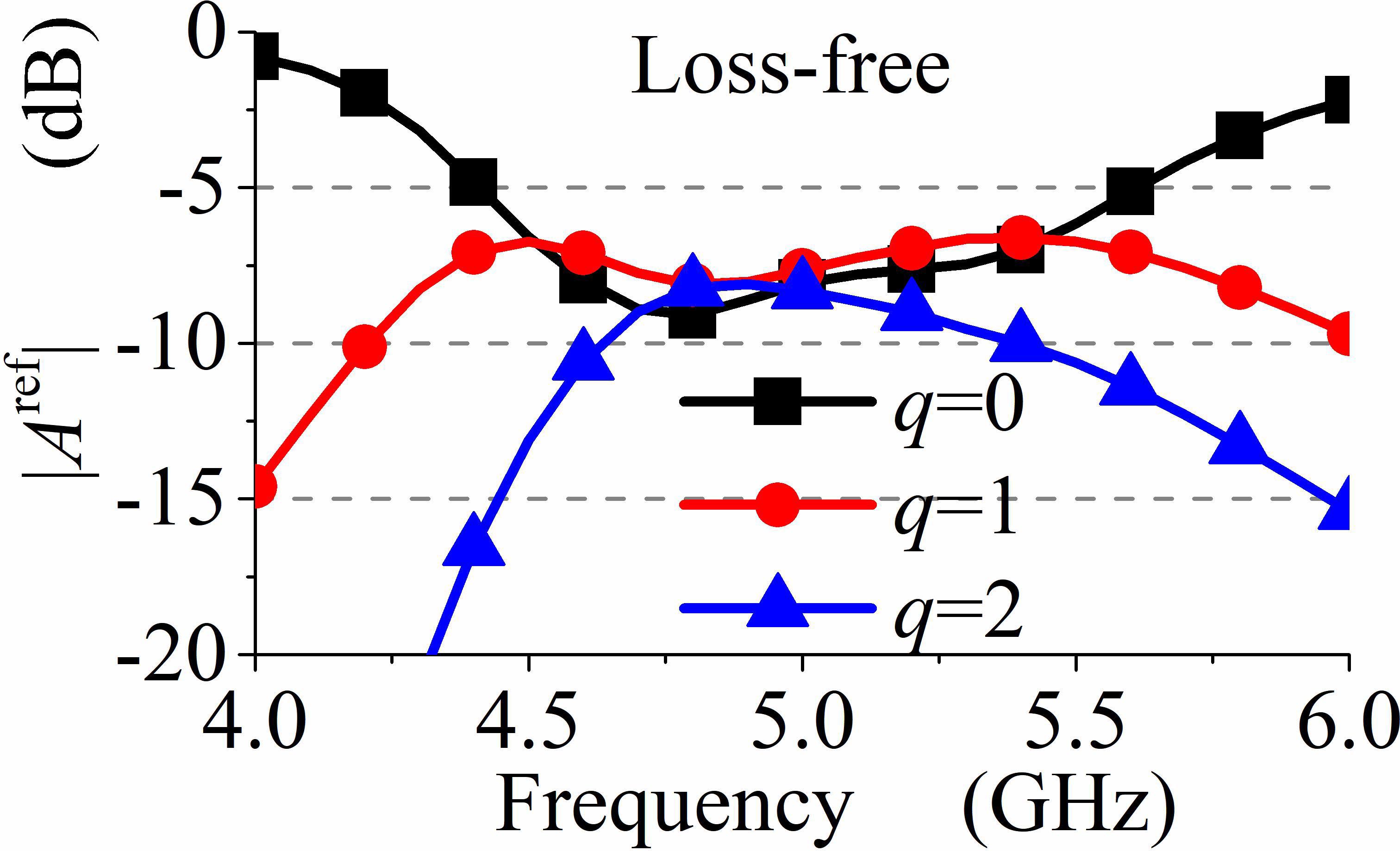
Figure 5: Reflection performance of the metagrating with multiple elements. (a) Loss-free metagrating. (b) Lossy metagrating.
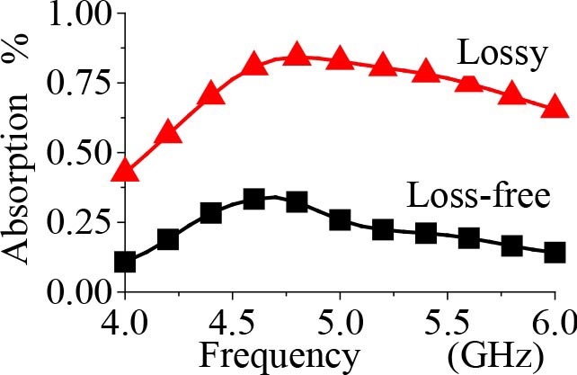
Figure 6: Absorption performance of the metagrating with multiple elements.
III. LOW-RCS METASURFACE EMBEDDED WITH THE METAGRATING
The low-RCS bands of the lossy metagratings designed above are narrow compared with the metasurface with the same substrate, which reduces the scope of application. In this section, we design a dual-band low-RCS metasurface embedded with a lossy metagrating. The lossy metagrating provides an extra narrow low-RCS band and has a small effect on the original low-RCS band of the metasurface.
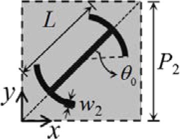
Figure 7: Polarization converter used for the low-RCS metasurface. (a) Element of the converter. (b) Performance of the converter. L = 5 mm, w= 0.5 mm, = 35, and P= 6 mm.
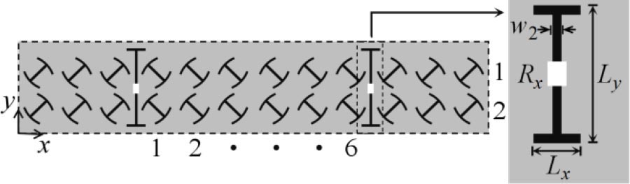
Figure 8: Low-RCS metasurface embedded with metagrating, where L= 1.8 mm, L= 11.5 mm, and R= 5 .
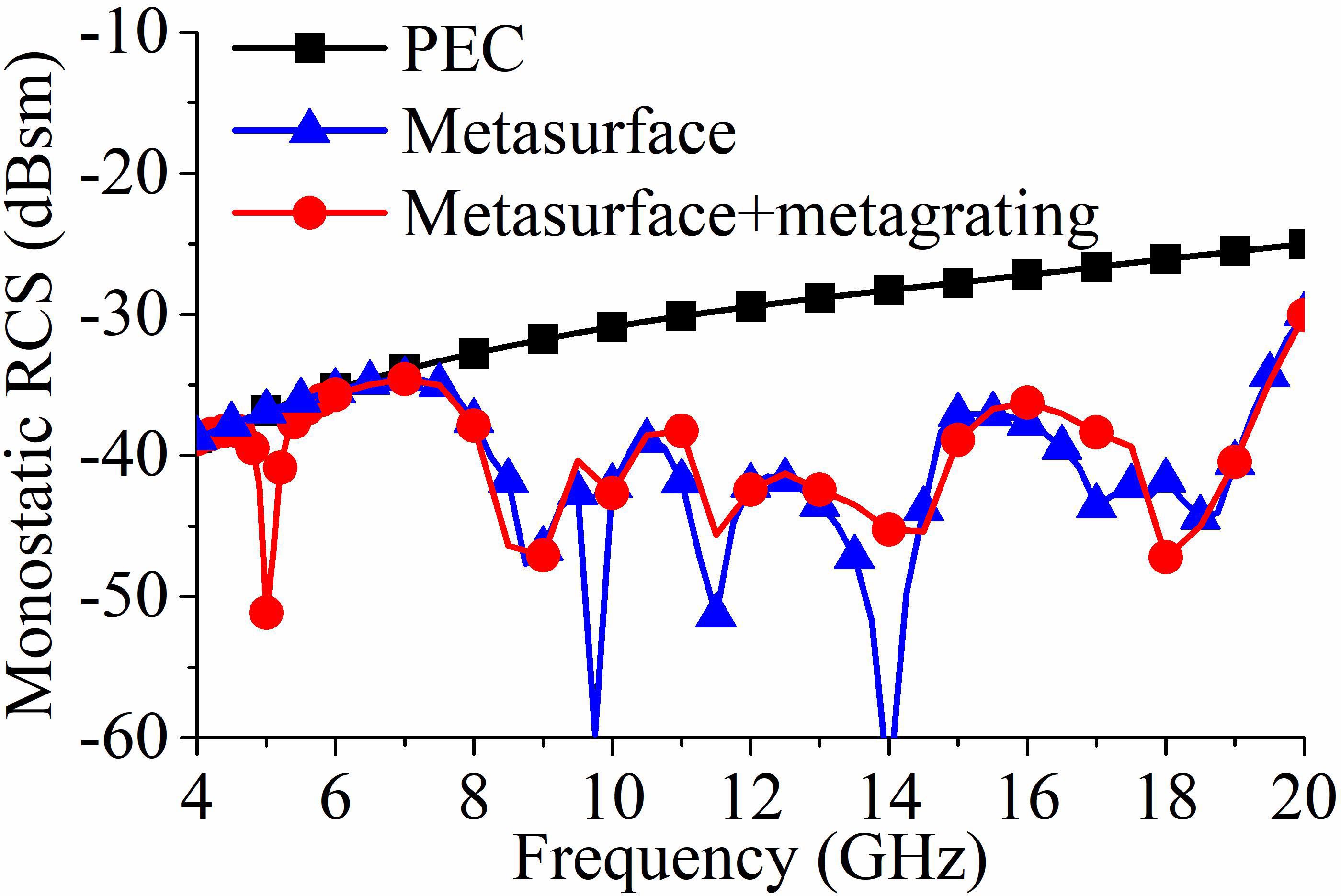
Figure 9: RCS of PEC, the low-RCS metasurface, and the metasurface embedded with the lossy metagrating.
The low-RCS metasurface is designed based on the polarization converter and scattering cancelation. The structure and performance of the element of the metasurface are shown in Figure 7. The thickness of the substrate is 2.5 mm and = 0. The bandwidth with the co-polarized reflections |R|= |R| 0.3 is 78% (8.5-19.5 GHz) and |R|= |R|= 1 at 5 GHz. Arranging the elements as the chessboard configuration, we obtain a 78% bandwidth with low RCS. By taking the cross-polarized reflections |R|= |R|= 0 at 5 GHz, the chessboard metasurface works as a uniform isotropic metasurface at 5 GHz. The method proposed for the design of metagrating in [9] is used with the consideration of the metasurface.
The structure of the designed low-RCS metasurface embedded with the metagrating is shown in Figure 8. The separation between the loaded lines is 36 mm and it is bigger than 0.5. The diffraction performance of the metasurface embedded with the metagrating under the normal illumination of a y-polarized TE plane wave is shown in Figure 9. It also shows the RCSs of the metasurface with no metagrating and the PEC with the same size. The metasurface with no metagrating reduces the RCS effectively within 8.5-19.5 GHz. The metasurface embedded with the metagrating provides an extra low-RCS band of 2% at 5 GHz and the original low-RCS band remains almost unchanged.
IV. CONCLUSION
The lossy metagrating is proposed to reduce RCS under the illumination of TE-polarized waves in this paper. The metagratings with both single element and multiple elements per supercell are studied. The theory based on the loss-free metagrating is used for the design of low-RCS metagrating, and numerical results show that lossy metagrating reduces the RCS effectively. The lossy metagrating is also incorporated into a wideband low-RCS metasurface to provide an extra low-RCS band and has a negligible effect on the low-RCS band of the metasurface. The metagrating has lesser elements than the metasurface and is conveniently loaded with lumped elements for RCS reduction.
ACKNOWLEDGMENT
This work was supported by the National Natural Science Foundation of China under Grants 62171093 and 62161048.
REFERENCES
[1] F. Costa, A. Monorchio, and G. Manara, “Analysis and design of ultra thin electromagnetic absorbers comprising resistively loaded high impedance surfaces,” IEEE Trans. Antennas Propag., vol. 58, no. 5, pp. 1551-1558, May 2010.
[2] F. Costa and A. Monorchio, “A frequency selective radome with wideband absorbing properties,” IEEE Trans. Antennas Propag., vol. 60, no.6, pp. 2740-2747, Jun. 2012.
[3] M. Paquay, J. C. Iriarte, I. Ederra, R. Gonzalo, and P. D. Maagt, “Thin AMC structure for radar cross-section reduction,” IEEE Trans. Antennas Propag., vol. 55, no. 12, pp. 3630-3638, Dec. 2007.
[4] T. Shang, J. Zhao, and J. Xu, “Convolution operations on coding metasurface for RCS reduction,” Applied Computational Electromagnetics Society (ACES) Journal, vol. 36, no. 10, pp. 1295-1300, Oct. 2021.
[5] W. B. Pan, C. Huang, M. B. Pu, X. L. Ma, J. H. Cui, B. Zhao, and X. G. Luo, “Combining the absorptive and radiative loss in metasurfaces for multi-spectral shaping of the electromagnetic scattering,” Sci. Rep., vol. 19, no. 6, pp. 21462, 2016.
[6] C. L. Holloway, E. F. Kuester, J. A. Gordon, J. O’Hara, J. Booth, and D. R. Smith, “An overview of the theory and applications of metasurfaces: The two-dimensional equivalents of metamaterials,” IEEE Antennas Propag. Mag., vol. 54, no. 2, pp. 10-35, Apr. 2012.
[7] Y. Ra’di, D. L. Sounas, and A. Al, “Metagratings: Beyond the limits of graded metasurfaces for wave front control,” Phys. Rev. Lett., vol. 119, no. 6, pp. 067404, Aug. 2017.
[8] O. Rabinovich and A. Epstein, “Analytical design of printed circuit board (PCB) metagratings for perfect anomalous reflection,” IEEE Trans. Antennas Propag., vol. 66, no. 8, pp. 4086-4095, Aug. 2018.
[9] V. Popov, F. Boust, and S. N. Burokur, “Controlling diffraction patterns with metagratings,” Phys. Rev. Applied, vol. 10, no. 1, pp. 011002, Jul. 2018.
[10] J. M. Liu, X. Fang, F. He, S. Q. Yin, W. Lyu, H. Geng, X. J. Deng, and X, P. Zheng, “Directional conversion of a THz propagating wave into surface waves in deformable metagraings,” Optics Express, vol. 29, no. 14, pp. 21749-21762, Jul. 2021.
[11] Y. Ra’di and A. Al, “Metagrating for efficient wavefront manipulation,” IEEE Photonics Journal, vol. 14, no. 1, pp. 227513, Feb. 2022.
BIOGRAPHIES

Kai Wang received the B.S. degree from the University of Electronic Science and Technology of China (UESTC), Chengdu, China, in 2015, where he is currently working toward the Ph.D. degree in radio physics.
His current research interests include metasurface design and computational electromagnetics.

Wei Shao received the B.E. degree in electrical engineering from the University of Electronic Science and Technology of China (UESTC) in 1998, and the M.Sc. and Ph.D. degrees in radio physics from UESTC in 2004 and 2006, respectively.
He joined the UESTC in 2007 and is currently a Professor there. From 2010 to 2011, he was a Visiting Scholar with the Electromagnetic Communication Laboratory, Pennsylvania State University, State College, PA, USA. From 2012 to 2013, he was a Visiting Scholar with the Department of Electrical and Electronic Engineering, Hong Kong University. His research interests include computational electromagnetics and antenna design.

Hua Li received the B.S. and the M.S. degrees from the Sichuan Normal University, Chengdu, China, in 1999 and 2002, respectively, and the Ph.D. degree from the University of Electronic Science and Technology of China (UESTC) in 2011.
In 2002, she joined UESTC, where she is currently an Associate Professor. From 2014 to 2015, she was a Visiting Scholar with the Department of Electrical and Computer Engineering, National University of Singapore, Singapore. Her current research interests include filtering antennas, reconfigurable antennas, implantable antennas, and metasurface antennas.

Bing-Zhong Wang received the Ph.D. degree in electrical engineering from the University of Electronic Science and Technology of China (UESTC) in 1988.
He joined the UESTC in 1984, where he is currently a Professor. He has been a Visiting Scholar with the
University of Wisconsin-Milwaukee, a Research Fellow with the City University of Hong Kong, and a Visiting Professor with the Electromagnetic Communication Laboratory, Pennsylvania State University, State College, PA, USA. His current research interests are in the areas of computational electromagnetics, antenna theory and technique, and electromagnetic compatibilityanalysis.
ACES JOURNAL, Vol. 37, No. 3, 320–325.
doi: 10.13052/2022.ACES.J.370309
© 2021 River Publishers