A Compact Planar Monopole UWB MIMO Antenna Design with Increased Isolation for Diversity Applications
S. Kolangiammal, L. Balaji, and G. Vairavel
Department of Electronics and Communication, Veltech Rangarajan Dr. Sakunthala R&D Institute of Science and Technology, Chennai 600062, India
vtd582@veltech.edu.in, drbalaji@veltech.edu.in
SRM Institute of Science and Technology, Chennai 603203, India
vairavelg@protonmail.com
Submitted On: March 29, 2021; Accepted On: February 26, 2022
Abstract
A compact planar multiple input multiple output (MIMO) antenna with four elements spanning the ultra-wideband (UWB) is proposed for diversity applications. The unit cells are positioned orthogonally to lower the mutual coupling by replicating the single antenna three times. A 35 35 1.6 mm UWB MIMO antenna is provided with a 50- impedance microstrip line on a 1.6-mm thick FR4 substrate. In the radiator and ground plane, some modifications are made to achieve the operating limits of this antenna between the frequencies of 3.1-10.6 GHz, thereby covering the entire frequency spectrum of the UWB with compact size. We conclude from the calculated results that the proposed antenna has high performance characteristics appropriate for UWB wireless indoor communication and diversity applications with compact size.
Keywords: Directive gain, diversity, envelope correlation coefficient, monopole, multiple input multiple output (MIMO), ultra-wideband antenna.
I. INTRODUCTION
In this developing age of technology, evolving technologies such as wireless communication must become more widely available and more reliable and faster. The ultra-wideband (UWB) technology can bring reliability and high data rate into the picture. It maintains a higher bandwidth while also having a low power density. The frequency range has been restricted to 3.1–10.6 GHz, with a bandwidth of 7.5 GHz.
A new approach is suggested in [1], where a four-element multiple input multiple output (MIMO) antenna with compact size is presented with low mutual coupling over an entire UWB range. This proposition suggests that we combine AFS miniaturizing techniques with MIMO orthogonal configuration, giving us both benefits. In [2], the designed antenna uses a novel integration-based orthogonal and asymmetric structure, four-directional decoupling and multiple-slot and slit (MSS) approaches. The symmetry in the structure and the four-directional escalators helps massively in reducing mutual coupling between antenna elements. The antenna’s inter-element coupling is reduced by using polarization diversity between the elements. The isolation is further improved by using a decoupling structure with inverted L- and Z-shapedstubs [3].
A technique of creating numerous slits in the ground plane made us benefit from the combined use of inductance and capacitance [4]. The works [5–8] suggest that parasitic elements between antenna elements can reduce the effect of inter-elements coupling since they act as reflectors. The work [9] suggests a neutralization line in the antenna elements to diminish the effects of mutual coupling, reducing the need for extra space. The asymmetrical radiation pattern of quasi-self-complementary structured antenna helps to diminish mutual coupling without using any decoupling techniques [10–12]. The work [13] suggests combining a pair of inverted L antennas (ILAs) with the monopole antenna, and each ILA is fed in anti-phase excitement, which helps us achieve a pattern and polarization diversities. The UWB antenna in [14] has a stubbed ground plane that helps achieve high bandwidth impedance without employing any decoupling structures. In [15], to increase the isolation and minimization, metamaterial inspired isolators are used. The work [16] suggests the ground length is reduced to improve the impedancebandwidth.
The diminished mutual coupling and diminished correlation coefficient for the array envelope are achieved by folding a patch with wall support and feeding this folded patched monopole antenna in three-dimensional U-slotted shapes [17]. When two antennas are excited at different modes in a ground plane, the mutual coupling will be reduced, and the desired radiation patterns can be achieved by not using any other decoupling structures [18]. The work [19] suggests that a VSWR value less than 2. Improvement in the impedance is achieved by etching the central patched metal. Beneath the radiator, a curve is inserted in the ground plane. The four-port diversity antenna in [20] is developed by repeating the unit cell and orthogonally positioning it to achieve high isolation. By varying the Sierpinski fractal, a better gain can be achieved [21]. The archetype Bowtie antenna is altered and aligned to improve the bandwidth through assailing the dipoles of patch and ground slot [22].
II. PROPOSED ANTENNA DESIGN
A. Single antenna design
The put-forward unit cell antenna with microstrip feed is modeled upon the FR4 substrate. The relative permittivity () and loss tangent of the FR4 substrate are 4.3 and 0.025, respectively. The proposed antenna occupied a volume of 18 mm 16 mm 1.6 mm. The measurements of different parameters have been displayed in Table 1.
The antenna consists of a radiator (combining two hexagons, two ellipses, five circles, and two rectangles) at the front along with tapered microstrip feed and defected rectangular ground structure in the rear. The geometric specifications of the novelty radiator are as follows: It contains five adjacent tangential circles of radius 1.5 mm each, placed in a straight line, mounted atop an ellipse of major axis x= 7 mm and minor axis y= 1 mm, which, in turn, is again mounted upon another ellipse of major axis x= 7.5 mm and minor axis y= 1.4 mm. This whole setup is burdened upon two hexagons of radius 2 mm placed side by side on corners of a rectangle of 3 6 mm. In addition to this, a thin rectangle of dimensions 15 2 mm passes through the array of five circles placed on top, which is used to lower the mutual coupling and enhance impedance matching performance. The inductive loading increases when the hexagons, ellipses, circles, and rectangles converge, raising the Q factor and resulting in a high inductive reactance, as shown by the followingequation:
| (1) |
The ground plane designed is a rectangular shape with a rectangular slot with dimensions 7 16 mmused to improve the bandwidth and impedance matching. The capacitance impact between the radiator and the ground plane was reduced when the slot was included, resulting in a substantial gain in bandwidth. The feed line of dimensions 9 3 mm is tapered to enhance current flooding near the radiator and obtain the required impedance bandwidth. Due to the modification in inductive reactance and capacitive reactance, both canceled with each other. Then the antenna behaved like a completely resistive load. A novelty concept of elliptical form radiator is an intelligent solution to bring a compact size UWB MIMO antenna. The final proposed antenna front and rear views are displayed in Figure 1. A fabricated single and MIMO antenna is displayed inFigure 2.
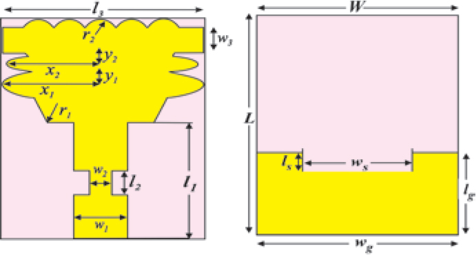
Figure 1: Front and rear views of unit cell antenna.
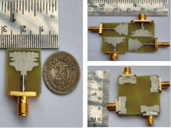
Figure 2: Fabricated single and MIMO antenna.
Table 1: Geometrical specifications of preferred monopole UWB unit cell antenna
| Parameters | x | y | x | y | r | r |
| Units (mm) | 7.5 | 1.4 | 7 | 1 | 2 | 1.5 |
| Parameters | L | l | l | l | l | l |
| Units (mm) | 18 | 9 | 2 | 15 | 7 | 1 |
| Parameters | W | w | w | w | w | w |
| Units (mm) | 16 | 3 | 1 | 2 | 16 | 7 |
The scattering parameters (S) of the antenna for both simulated and measured across the desired bandwidth and are below 10 dB; it is depicted in Figure 3. The couplings between small ground surface, connector losses, and cable misalignment are the reasons for deviations in the measured S-parameters.
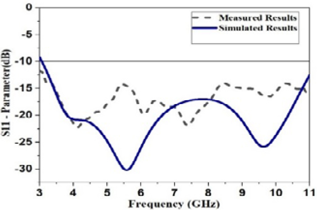
Figure 3: Simulated and measured reflection coefficient of the monopole UWB unit cell antenna.
B. MIMO antenna design
The single antenna is replicated and grouped in an orthogonal pattern to design a multi-port antenna to attain high isolation. All radiating elements are arranged upon the same plane. Altogether, the total dimensions of the L W hs of a four-port antenna are 35 35 1.6 mm, hs representing the substrate’s height. The measurement setup of the fabricated antenna with the anechoic chamber is depicted in Figure 4.
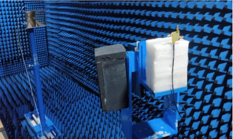
Figure 4: Proposed UWB MIMO antenna measurement in anechoic chamber.
III. DIVERSITY PERFORMANCE ANALYSIS
CST Microwave Studio Software is used for designing and developing the proposed antenna by making parametric analysis and optimization [28]. Anritsu MS2703 vector network analyzer is used to measure propounded MIMO/diversity antenna performance.
A. Mutual coupling
The monopole UWB MIMO antenna incorporates four antennas that look very near to one another. As a result, one antenna would face interference due to the radiation of the other.
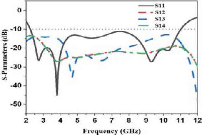
Figure 5: S-parameter simulated results of monopole UWB MIMO antenna.
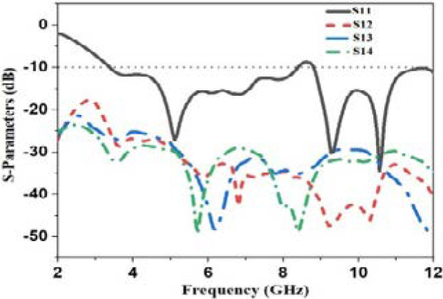
Figure 6: S-parameter measured results of monopole UWB MIMO antenna.
The mutual coupling is reduced by assembling the modified ground structures, and identical antennas are arranged orthogonally. This antenna has been fabricated to offer mutual coupling less than 35 dB for the entire bandwidth range. Simulated and measured S-parameter results of monopole UWB MIMO antenna are depicted in Figures 5 and 6. Thus, we can see that impedance matching and high isolation are obtained using the etched ground plane with slot. Hence, the required result has been obtained.
B. Envelope correlation coefficient (ECC)
The correlation between the radiating elements is the important diversity parameter of the MIMO antenna. The degree of independence of the two antennas’ radiation patterns is explained using the envelope correlation coefficient (ECC). Ideally, two antennas’ radiation patterns are entirely independent of each other. The ECC should be 0, but its real value should not exceed 0.5. The ECC is calculated by substituting the S-parameters in eqn (2) [23]. From Figures 7 and 8, we discovered that ECC is much less than 0.001, which can also be regarded as a good ECC value.
| (2) |
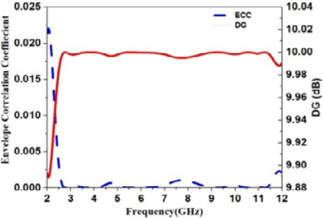
Figure 7: Simulated diversity gain and ECC of monopole UWB MIMO antenna.
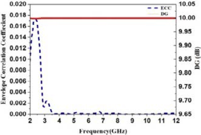
Figure 8: Measured diversity gain and ECC of monopole UWB MIMO antenna.
C. Diversity gain (DG)
The diversity gain (DG) of the monopole UWB MIMO antenna ought to be apex so that one can keep the wireless communication system more reliable and produce good quality. Its ideal value is 10 dB. Using the formula in eqn (3) [23], the value of the DG can be calculated for the proposed antenna. From Figures 7 and 8, we can evidence that the maximum value of DG is 9.999 dB.
| (3) |
D. TARC
The ratio between the squared value of the reflected power and its incident power is called TARC. N port antenna’s TARC ratio can be presented as in the following equation:
| (4) |
where x represents incident signals and y represents reflected signals. The scattering matrix of 2 2 antenna arrays can be patterned as in the following equation:
| (5) |
In the MIMO antenna, the phase of every excitation signal is arbitrary. The propagation environment contributes to further randomizing the signal phases before the signal reaches the receiver. So the MIMO channel signal is considered a random phase and independent and identically distributed. Gaussian random variables’ sum or difference gives the Gaussian values, and reflected signals can be expressed as in the following equations [23]:
| (6) |
| (7) |
Therefore, TARC is described as follows in eqn (9):
| (8) |
| (9) |
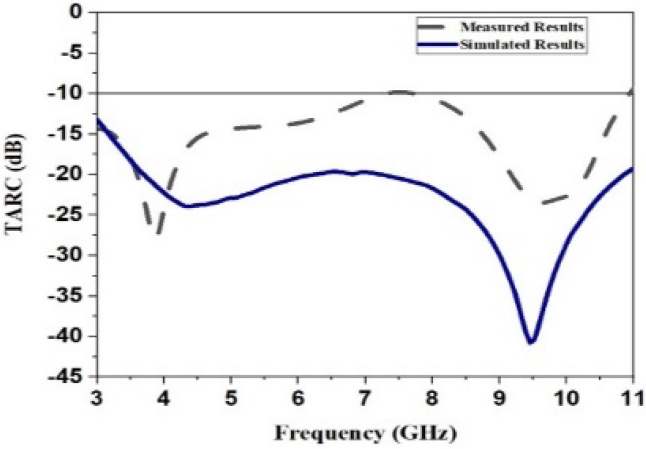
Figure 9: TARC of the monopole UWB MIMO antenna.
The value of TARC must be less than 10 dB to attain the best operation in MIMO antennas. The received TARC is proven in Figure 9. It well agrees with the default standard values of TARC.
E. MEG
MEG is defined as the division of power obtained with the aid of a diversity antenna with power received by way of an isotropic antenna. Using the following relations [24], the MEG value is calculated for the MIMO antenna system. The MEG1 and MEG2 can be calculated from the following equation:
| (10) |
For a better MIMO antenna system with equal power, the difference between MEG-1 and MEG-2 should be equal to 0 dB. Figures 10 and 11 are well known to show that MEG-1 and MEG-2 are identical because the proposed radiator gives improved range overall performance.
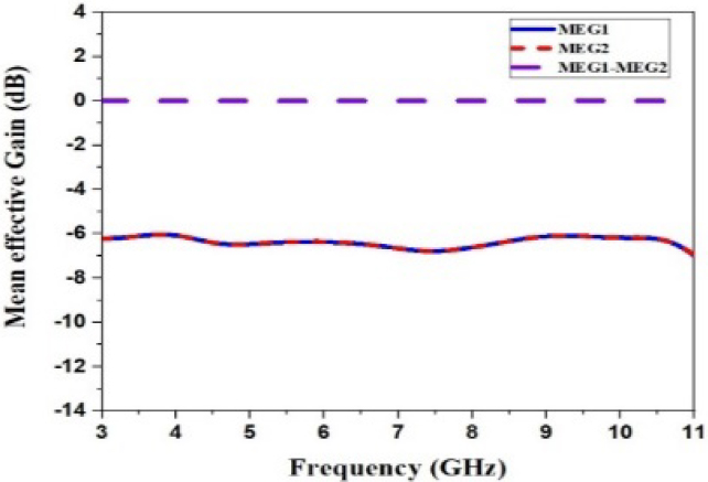
Figure 10: Simulated MEG of monopole UWB MIMO antenna.

Figure 11: Measured MEG of monopole UWB MIMO antenna.
F. CCL
Channel capacity loss (CCL) refers to the maximum message rate as far as the message transmits continuously through the communication channel without any losses. It can be estimated by the usage of the following components and expressed in the following equation [24]:
| (11) |
| (12) |
where
The CCL value should not be greater than 0.4 bits/S/Hz ideally. Figure 12 shows the proposed MIMO antenna CCL value over the operating frequency range, and acceptable CCL values are achieved.
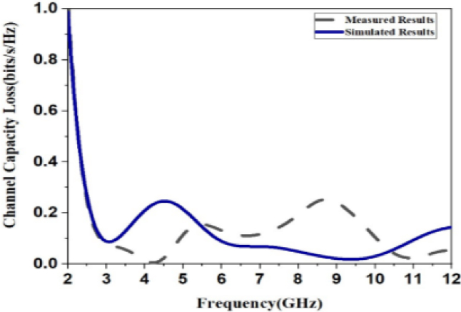
Figure 12: CCL of the monopole UWB MIMO antenna.
G. Multiplexing efficiency
Figure 13 indicates the multiplexing efficiency measured and simulated results of the proposed MIMO antenna. The multiplexing efficiency of the MIMO antenna is defined as the difference in the power required attaining a given capacity for an antenna under test concerning ideal reference MIMO antenna. As per eqn (13) [25], the MUX for a uniform angular power spectrum and high signal-to-noise ratio can be expressed as
| (13) |
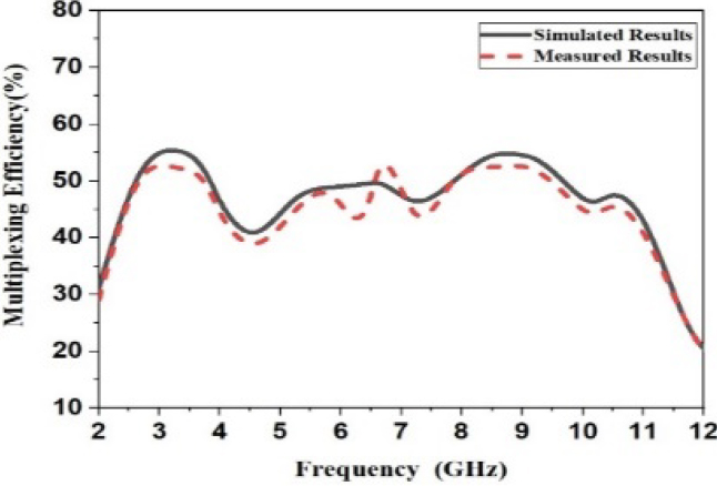
Figure 13: Multiplexing efficiency of monopole MIMO ultra-wideband antenna.
Here, 1 represents the total efficiency of antenna 1 and 2 represents the total efficiency of antenna 2.
For the proposed antenna, measured and simulated gain is shown in Figure 14. From this, it is evident that simulated and measured gain changed in the range from 1.5 to 4 dBi. In [26], PSO and the curve fitting approaches are presented. Sierpinski’s fractal antenna design can be modified to achieve a gain of 8.98 dB. For the proposed antenna, measured and simulated radiation efficiency is shown in Figure 15. Simulated and measured radiation efficiency changed from 75% to 90%.
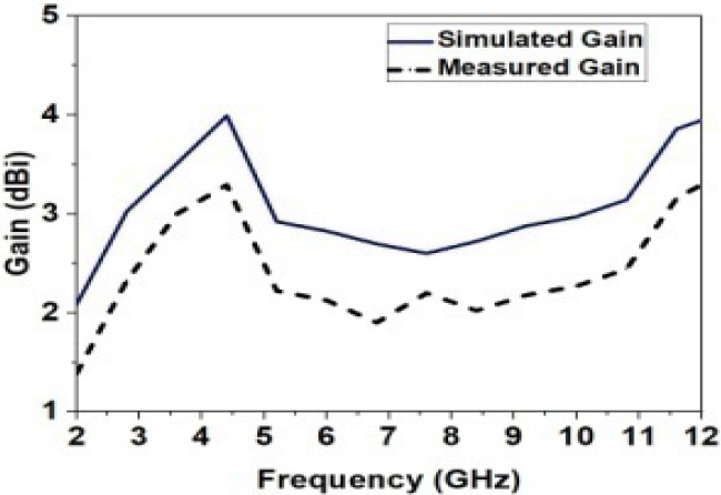
Figure 14: The gain of monopole UWB MIMO antenna.
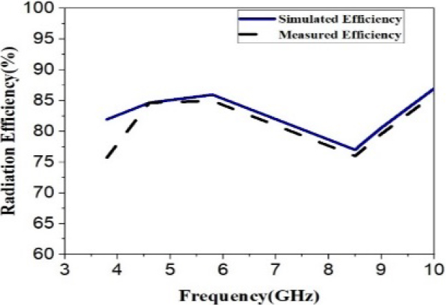
Figure 15: Radiation efficiency of monopole UWB MIMO antenna.
H. Radiation patterns
The designed antennas’ simulated and measured H-plane and E-plane radiation patterns at 3.8 GHz frequency are depicted in Figures 16 (a) and (b).
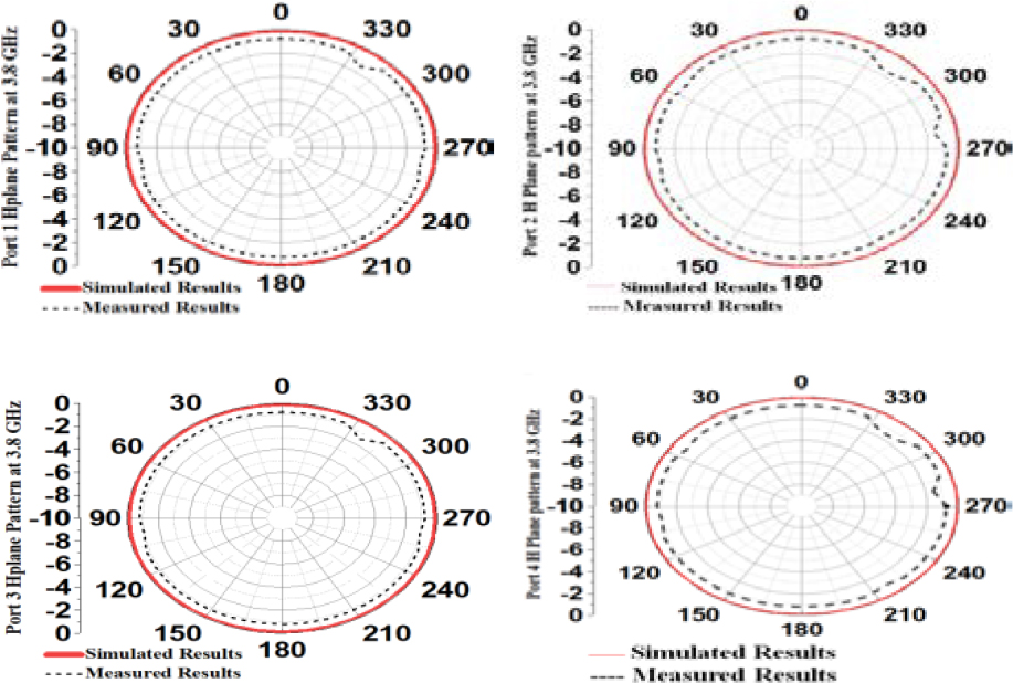
Figure 16: (a) H-plane pattern of Port 1, Port 2, Port 3, and Port 4 of the proposed UWB MIMO antenna at 3.8 GHz.
Figure 16: (b) E-plane pattern of Port 1, Port 2, Port 3, and Port 4 of the proposed UWB MIMO at 3.8 GHz.
Table 2: Comparison table
| Ref | Ports | Size (mm) | Isolation (dB) |
TARC (dB) |
ECC | CCL (bits/s/Hz) |
GHz |
| 1 | 4 | 40 70% 40 | 17 | - | 0.03 | - | 2.94–14 |
| 2 | 4 | 39 70% 39 | 22 | 20 | 0.02 | 0.2 | 2.3–13.7 |
| 3 | 4 | 70 70% 41 | 17 | 9 | 0.012 | 0.4 | 3.1–12 |
| 4 | 4 | 40 70% 40 | 20 | - | - | - | 3–11.5 |
| 5 | 4 | 40 70% 40 | 10 | - | - | - | 3–11 |
| 6 | 4 | 36 70% 36 | 15 | - | - | - | 3.1–10.6 |
| 7 | 4 | 56 70% 56 | 20 | - | - | - | 3–11 |
| 8 | 4 | 50 70% 39 | 17 | - | - | - | 2.7–12 |
| 9 | 4 | 75 70% 75 | - | - | 0.1 | - | 3.1–17.3 |
| 10 | 4 | 35 70% 35 | 70%=20 | - | 0.5 | - | 3–12 |
| 11 | 4 | 40 70% 40 | 70%=20 | - | 0.04 | - | 2.9–12.1 |
| 12 | 4 | 24 70% 24 | 70%=20 | - | 0.5 | - | 3.1–10.5 |
| 15 | 2 | 13.5 70% 34 | 70%=19 | 4 | - | - | 3–11 |
| 17 | 2 | 56 70% 56 | 22 | - | 0.001 | - | – |
| 18 | 2 | 50 70% 85 | 20 | - | 0.03 | - | 2–9.5 |
| 19 | 2 | 42 70% 24 | 70%=15 | - | 0.5 | - | 3.1–10.9 |
| 20 | 4 | 40 70% 40 | 20 | - | 0.001 | - | 3.1–10.6 |
| 23 | 2 | 18 70% 34 | 22 | 20 | 0.001 | - | 2.93–20 |
| Prop | 4 | 35 70% 35 | 35 | 20 | 0.001 | 0.4 | 3.1–11 |
Using this pattern, we can see that the proposed MIMO antenna illustrates pattern diversity at the 3.8-GHz frequency band. The patterns at Port 1 and Port 3 are 180 rotated with each other; similarly, the patterns in Ports 2 and 4 are 180 rotated each other. The proposed antenna H-plane radiation pattern is omnidirectional, and the E-plane pattern is dumbbell-shaped [27].
Table 2 presents the comparative chart for the proposed antenna design with the reported antenna. In this comparison, it is observed that the proposed antenna has achieved significant results in terms of CCL of less than 0.4 bits/s/Hz, TARC of 10dB, ECC of 0.001, DG of 9.999 dB, and MEG of 3 dB.
IV. CONCLUSION
The antenna elements are arranged in orthogonal, and then it appears to be the most effective solution to diminish the mutual coupling between UWB MIMO antennas and hence achieve compact size. The mutual coupling value of the proposed antenna is less than 35 dB and has been achieved successfully. The radiating antenna with compact size has been fabricated using the dimensions of 35 35 mm having the thickness of the substrate 1.6 mm, and this antenna is used for diversity applications.
REFERENCES
[1] Saad, R. Ayman Ayd, and Hesham A. Mohamed. “Conceptual design of a compact four-element UWB MIMO slot antenna array,” IET Microwaves, Antennas & Propagation, vol. 13, no. 2, pp. 208-215, 2019.
[2] Tang, Zhijun, Xiaofeng Wu, Jie Zhan, Shigang Hu, Zaifang Xi, and Yunxin Liu. “Compact UWB-MIMO antenna with high isolation and triple band-notched characteristics,” IEEE Access, vol. 7, pp. 19856-19865, 2019.
[3] Yang, LingSheng, Ming Xu, and Chun Li. “Four-Element MIMO antenna system for UWB applications,” Radio engineering, vol. 28, no. 1, pp. 60-67, 2019.
[4] Srivastava, Gunjan, Santanu Dwari, and B. K. Kanuijia. “A compact 4 4 ultrawideband (UWB) band notched MIMO antenna,” In 2014 IEEE International Microwave and RF Conference (IMaRC), pp. 198-200, IEEE, 2014.
[5] Mao, Chun-Xu, and Qing-Xin Chu. “Compact coradiator UWB-MIMO antenna with dual polarization,” IEEE transactions on antennas and propagation, vol. 62, no. 9, pp. 4474-4480, 2014.
[6] Zhang, Jing-Yi, Fan Zhang, and Wen-Peng Tian. “Compact 4-port ACS-fed UWB-MIMO antenna with shared radiators,” Progress In Electromagnetics Research Letters, vol. 55, pp. 81-88, 2015.
[7] Li, Jian-Feng, Qing-Xin Chu, Zhi-Hui Li, and Xing-Xing Xia. “Compact dual band-notched UWB MIMO antenna with high isolation,” IEEE transactions on antennas and propagation, vol. 61, no. 9, pp. 4759-4766, 2013.
[8] Khan, M. S., A. D. Capobianco, S. Asif, A. Iftikhar, B. Ijaz, and B. D. Braaten. “Compact 4 4 UWB-MIMO antenna with WLAN band rejected operation,” Electronics Letters, vol. 51, no. 14, pp. 1048-1050, 2015.
[9] Kayabasi, Ahmet, Abdurrahim Toktas, Enes Yigit, and Kadir Sabanci. “Triangular quad-port multi-polarized UWB MIMO antenna with enhanced isolation using neutralization ring,” AEU-International Journal of Electronics and Communications, vol. 85, pp. 47-53, 2018.
[10] Zhu, Jianfeng, Shufang Li, Botao Feng, Li Deng, and Sixing Yin. “Compact dual-polarized UWB quasi-self-complementary MIMO/diversity antenna with band-rejection capability,” IEEE Antennas and Wireless Propagation Letters, vol. 15, pp. 905-908, 2015.
[11] Yu, Jian-Feng, Xiang Long Liu, Xiao-Wei Shi, and Zedong Wang. “A compact four-element UWB MIMO antenna with QSCA implementation,” Progress In Electromagnetics Research Letters, vol. 50, pp. 103-109, 2014.
[12] Srivastava, Gunjan, Akhilesh Mohan, and Ajay Chakraborty. “A compact multidirectional UWB MIMO slot antenna with high isolation,” Microwave and Optical Technology Letters, vol. 59, no. 2, pp. 243-248, 2017.
[13] Wang, Xin, Zhenghe Feng, and Kwai-Man Luk. “Pattern and polarization diversity antenna with high isolation for portable wireless devices,” IEEE Antennas and Wireless Propagation Letters, vol. 8, pp. 209-211, 2008.
[14] Y. Wu, K. Ding, B. Zhang, J. Li, D. Wu, and K. Wang, 2018. “Design of a compact UWB MIMO antenna without decoupling structure,” International Journal of Antennas and Propagation, 2018.
[15] Wang, Fei, Zhaoyun Duan, Shifeng Li, Zhan-Liang Wang, and Yu-Bin Gong. “Compact UWB MIMO antenna with metamaterial-inspired isolator,” Progress In Electromagnetics Research C, vol. 84, pp. 61-74, 2018.
[16] Christydass, Samuel Prasad Jones, and Nagarajan Gunavathi. “Dual-Band complementary split-ring resonator engraved rectangular monopole for GSM and WLAN/WiMAX/5G Sub-6 GHz band (new radio band),” Progress In Electromagnetics Research C, vol. 113, pp. 251-264, 2021.
[17] Jiang, Zhi Hao, Lei Zhang, Yan Zhang, Chao Yu, Longzhu Cai, Sidou Zheng, and Wei Hong. “A compact triple-band antenna with a notched ultra-wideband and its MIMO array,” IEEE Transactions on Antennas and Propagation, vol. 66, no. 12, pp. 7021-7031, 2018.
[18] Zhao, Xing, Swee Ping Yeo, and Ling Chuen Ong. “Planar UWB MIMO antenna with pattern diversity and isolation improvement for mobile platform based on the theory of characteristic modes,” IEEE Transactions on Antennas and Propagation, vol. 66, no. 1, pp. 420-425, 2017.
[19] Alsath, M. Gulam Nabi, and Malathi Kanagasabai. “Compact UWB monopole antenna for automotive communications,” IEEE Transactions on Antennas and Propagation, vol. 63, no. 9, pp. 4204-4208,2015.
[20] S. Kolangiammal, and G. Vairavel. “Compact planar monopole UWB MIMO antenna for diversity applications,” In Advances in Smart System Technologies, pp. 281-291, Springer, Singapore,2021.
[21] Singh, Amandeep, and Surinder Singh. “Design and optimization of a modified sierpinski fractal antenna for broadband applications,” Applied Soft Computing, vol. 38, pp. 843-850, 2016.
[22] Solanki, Lakhvinder Singh, Surinder Singh, and Dharmendra Singh. “Modified wideband bowtie antenna for WLAN and high speed data communication applications,” Wireless Personal Communications, vol. 95, no. 3, pp. 2649-2663, 2017.
[23] Chandel, Richa, Anil Kumar Gautam, and Karumudi Rambabu. “Tapered fed compact UWB MIMO-Diversity antenna with dual band-notched characteristics,” IEEE Transactions on Antennas and Propagation, vol. 66, no. 4, pp. 1677-1684,2018.
[24] Ibrahim, A. Ahmed, Jan Machac, and Raed M. Shubair. “UWB MIMO antenna for high speed wireless applications,” The Applied Computational Electromagnetics Society (ACES) Journal, pp. 1294-1299, 2019.
[25] Tian, Ruiyuan, Buon Kiong Lau, and Zhinong Ying. “Multiplexing efficiency of MIMO antennas,” IEEE Antennas and Wireless Propagation Letters, vol. 10, pp. 183-186, 2011.
[26] Singh, Amandeep, and Surinder Singh. “A modified coaxial probe-fed sierpinski fractal wideband and high gain antenna,” AEU-International Journal of Electronics and Communications, vol. 69, no. 6, pp. 884-889, 2015.
[27] Song, Ze-Lin, Zhao-Jun Zhu, and Lu Cao. “High isolation UWB-MIMO compact micro-strip antenna,” The Applied Computational Electromagnetics Society (ACES) Journal, vol. 33, no. 3, pp. 293-297, Mar. 2018.
[28] CST Microwave Studio, ver. 2018, Computer simulation technology, Framingham, MA, 2018.
BIOGRAPHIES

S. Kolangiammal received the M.Tech. degree from SRM University. She is currently working toward the Ph.D. degree with the Vel Tech Rangarajan Dr. Sagunthala R&D Institute of Science and Technology.
She is currently working as an Assistant Professor with the Department of ECE, SRMIST. Her research interests include antennas and propagation and wireless communications.

L. Balaji received the Ph.D. degree from Anna University.
He is currently an Associate Professor with the Department of ECE, Vel Tech Rangarajan Dr. Sagunthala R&D Institute of Science and Technology. His research interests include video coding, multimedia compression, and wireless communication and networking with IoT.

G. Vairavel received the Ph.D. degree from Anna University.
He is currently a Professor with the Centre for Applied Research in Education, SRMIST. His research interests include MIMO antenna design, software defined radio, and wireless communication.
ACES JOURNAL, Vol. 37, No. 4, 458–465.
doi: 10.13052/2022.ACES.J.370411
© 2021 River Publishers