Substrate Integrated Waveguide Antenna at Millimeter Wave for 5G Application
Yaqdhan Mahmood Hussein, Mohamad Kamal A. Rahim, Noor Asniza Murad, Hatem Oday Hanoosh, and Norsaidah Binti Muhamad Nadzir
Advance RF and Microwave Research Group (ARFMRG), School of Electrical Engineering, Faculty of Engineering, Universiti Teknologi Malaysia, UTM Johor Bahru, Johor 81310, Malaysia
Yaqthanm.79@gmail.com, mdkamal@utm.my, noorasniza@utm.my, norsaidah2@graduate.utm.my
Information Technology and Communication (ITC) Al-Furat Al-Awsat Technical University, Sammawah, Iraq
Department of Computer Techniques Engineering, College of Information Technology, Imam Ja’afar Al-Sadiq University, Samawah 66001, Al Muthanna, Iraq
Hatem.altaee1990@gmail.com
College of Engineering Electronics and Communications Engineering, Al Muthanna University, Iraq
Submitted On: April 12, 2021; Accepted On: March 21, 2022
Abstract
This paper presents a dual-band slot antenna using substrate integrated waveguide (SIW) technology at 26 and 28 GHz. High loss is one of the main challenges faced by 5G base station network due to the severe path loss at high frequency. Hence, high gain antennas are required for 5G base station applications to overcome path loss issue. Hence, this work designs a high gain SIW antenna based on slot technology to excite dual-bands with high gain capability. The antenna is designed with two slots shaped to resonate at two different frequencies: 26 and 28 GHz. The antenna is analyzed using CST software and fabricated on Roger RT5880 substrate with permittivity of 2.2 and lost tangent of 0.0009 with thickness of 0.508 mm. The design operates at 26 and 28 GHz with measured reflection coefficients less than -10 dB. Measured high gains of 8 and 8.02 dB are obtained at 26 and 28 GHz, respectively. Overall, the antenna showed good performance that would benefit the fifth-generation applications.
Keywords: Millimeter-wave antenna, SIW technology, (5G) applications.
I. INTRODUCTION
With the development of wireless communication technology, the dual-band and multiband antennas have the tendency for future communications due to the advantages of compactness, high integration, and low cost. Recently, several promising millimeter-wave bands have been released for 5G wireless communication systems. Therefore, broadband dual-band antennas are in demand for future millimeter-wave wireless applications. For the design of dual-band antennas, there are two basic technical challenges which limit the use of this technology. This includes simultaneous operation with a compact configuration and broadband operation in each of the bands.
Several types of dual-band antenna have been investigated in literature. Normally, two types of dual-band solutions, namely hybrid antennas and multimode antennas are used. The hybrid dual-band antenna is the combination of antennas resonating at different frequencies, respectively, but simultaneously fed by only one port. Furthermore, these antennas operate at different types of mode or appear to be arranged in a separated aperture. Different types of antennas have been combined and different types of resonant mode of antennas have been employed for the dual-band operation, such as the slot monopole [1], dielectric resonator antenna (DRA) slot [2], and slot patch [3]. In addition to that, the same types of antennas with different shapes or sizes have also been proposed for dual-band operation by using different modes of transmission line and separated placement, such as the substrate integrated waveguide (SIW) fed slots [4]. An antenna of a modified cavity with two layers was proposed to realize resonance and directional radiation patterns over a frequency band at millimeter wave in [5–7]; however, these papers come with complex design and bulky size.
This paper introduces SIW antenna with slot. This antenna was implemented using SIW technology with roger RT 5880 as substrate with thickness of 0.508 mm. The design is on a fully ground plane, the reflection coefficient of it is less than 10 dB as the result of reflection coefficient were obtained from dual-band. The operating frequency dual-band resonates at 26 and 28 GHz. The paper is organized as follows. Section II gives a brief overview of the methodology for the antenna designed consideration. The simulated and measured results are summarized in Section III. Finally, Section IV draws conclusions.
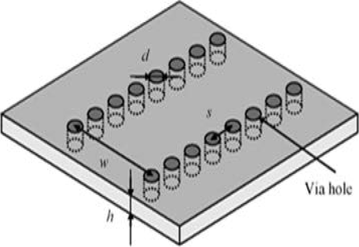
Figure 1: General structure of a substrate integrated waveguide [10].
II. ANTENNA DESIGN
Figure 1 shows the general structure of SIW which consists of a rectangular waveguide, two rows of periodic holes, and a substrate in between metal planes [8]. The proposed SIW antennas are designed using Rogers RT5880 substrate with dielectric constant of 2.2 and loss tangent of 0.0009, and thickness of 0.508 mm. The vias diameter, D, and spacing, S, are calculated using equations in [9]. Figure 2 shows the dimensions of the proposed antennas at millimeter wave with dual-band performance. This design comes with two different shapes of slot according to different position at the top of metal. Since SIW design generally works in TE1, 0 mode, m = 1, n = 0. Therefore, the equation for cutoff frequency is reduced to
| (1) |
where a is the total broad side dimension of the rectangular waveguide. Next, a is the width of dielectric field waveguide (DFW)
| (2) |
The design equations for SIW, which are found by W, are the separation between via rows (center to center)
| (3) |
Then, the equations for the separation distance “S” and diameter “D” control the radiation loss and return loss are as follows:
| (4) |
| (5) |
| (6) |
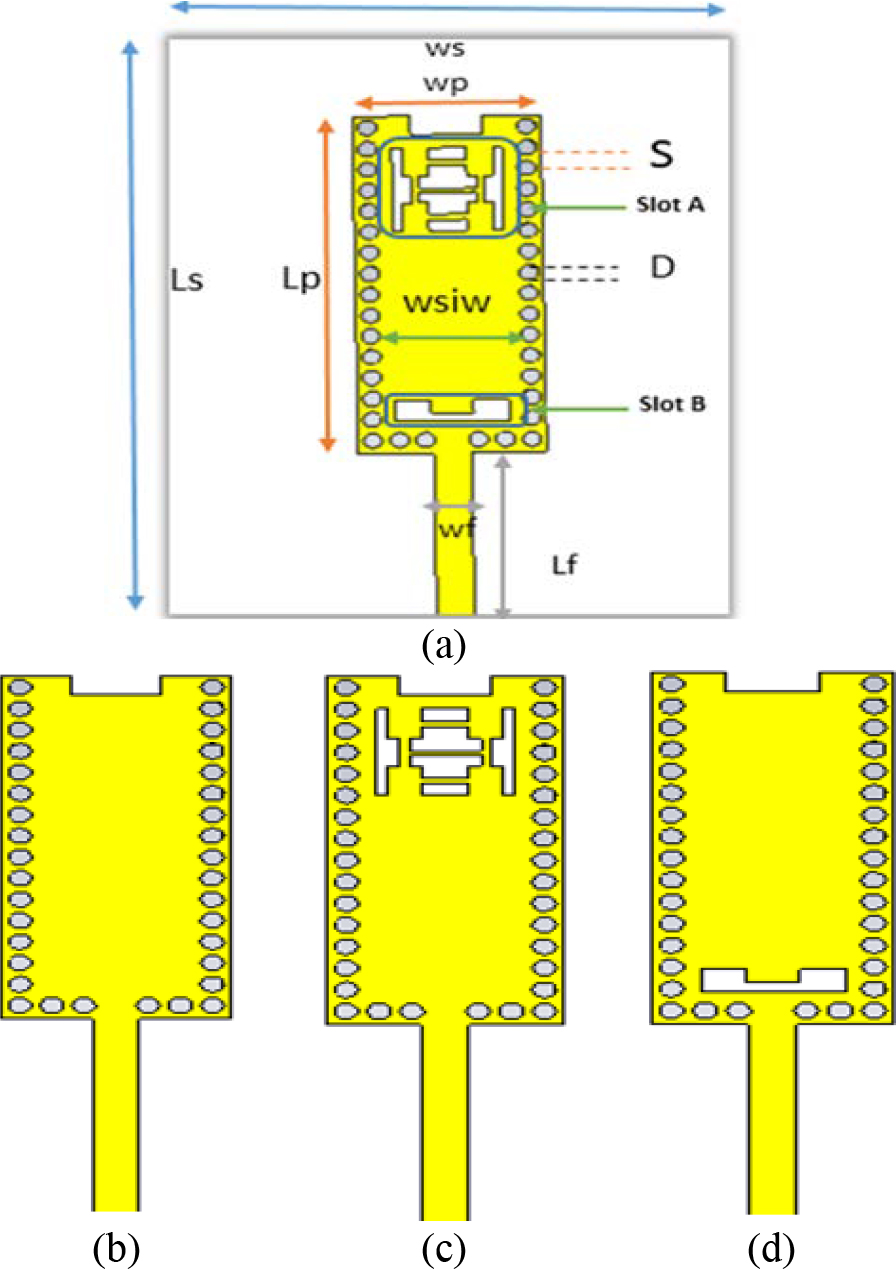
Figure 2: Simulation structure of the SIW antenna. (a) Main structure with slots A and B. (b) Design without slot. (c) Design with slot A. (d) Design with slot B.
Figure 2 (a) refers to main shape structure which consists of two columns as vias at both edges of the structure to prevent signal from passing through the edges of the patch, especially when millimeter-wave frequency loss becomes higher than lower frequency. The final dimensions of the structure designed at 26 GHz are shown in Table 1.
Table 1: Dimensions of main structure
| Variable | Name | Size (mm) |
|---|---|---|
| W | Width of substrate | 2.08 |
| L | Length of substrate | 2.8253 |
| W | Width of patch | 0.675 |
| L | Length of patch | 1.54 |
| W | Width of SIW | 0.57 |
| D | Diameter | 0.069 |
| S | Space between vias | 0.095 |
| W | Width of feed line | 0.268 |
| L | Length of feed line | 0.136 |
| Thickness of the substrate | 0.044 |
III. DISCUSSION BASED ON PARAMETRIC STUDY
The distance between vias(s) enables the dual-band antenna to control losses. Whenever the gap(s) is smaller, the antenna will achieve less loss because at the top of vias edges, electric will reflect around vias where some of them is radiated at the top of patch and the rest will have pushed downwards to create unwanted feedback, which is represented in slot A and slot B, respectively, as can be seen in Figure 2. Slot A creates radiation at 26 GHz because it depends on the distance between slots and feed line, slot A has multi-different slots arranged equally on the middle of antenna to keep angle of the beam at (0) and ensures that it focuses on the target substrate.
Slot B produces radiation at 28 GHz because of its size and position. Slot B has greater effect on radiation because of its position closer to the feed line. This shows that it is located closer to the main surface current (red zone). In addition, slot B proved high bandwidth.
The main parameter of this design study is the diameter of vias. When vias is 0.6 mm as can be seen in Figure 3 design has slot A, slot B and without slots the reflection coefficient becomes narrow band and it does not resonate at 26 and 28 GHz. As can be seen in Figure 4, when the diameter of vias is 1 mm and it has two slots (slot A and slot B), the reflection coefficient will not achieve dual-band frequency. When the diameter of vias is 0.8 mm, the design achieves dual-band resonance at (23-28) which can be seen in two cases. Based on Figure 5, this happens when design has slot A and without any slots.
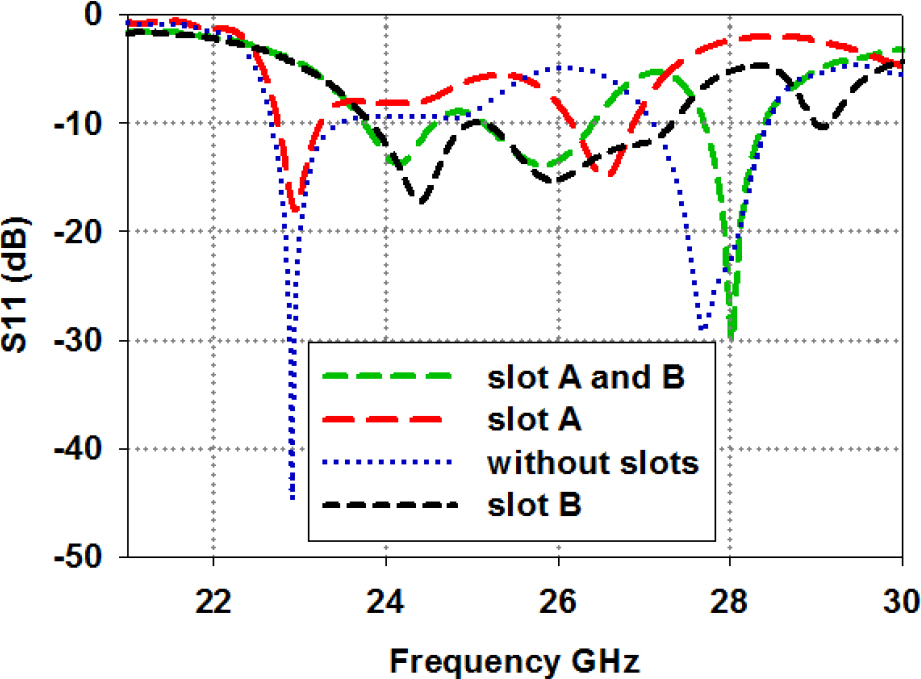
Figure 3: Different reflection coefficient of the SIW structure with vias diameter (0.6 mm) depends on the different cases slots.
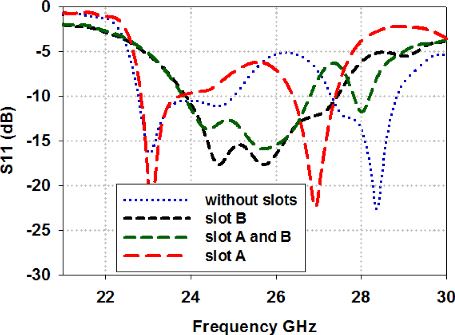
Figure 4: Different reflection coefficient of the SIW structure with vias diameter (1 mm) depends on the different case slots.
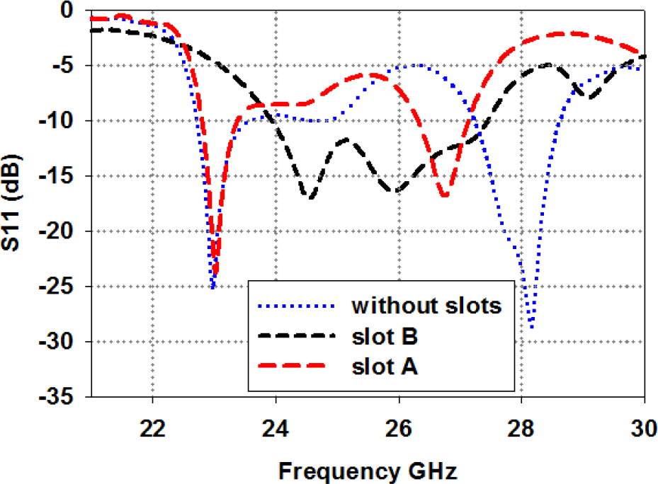
Figure 5: Different reflection coefficient of the SIW structure with vias diameter (0.8 mm) depends on the different cases slots.
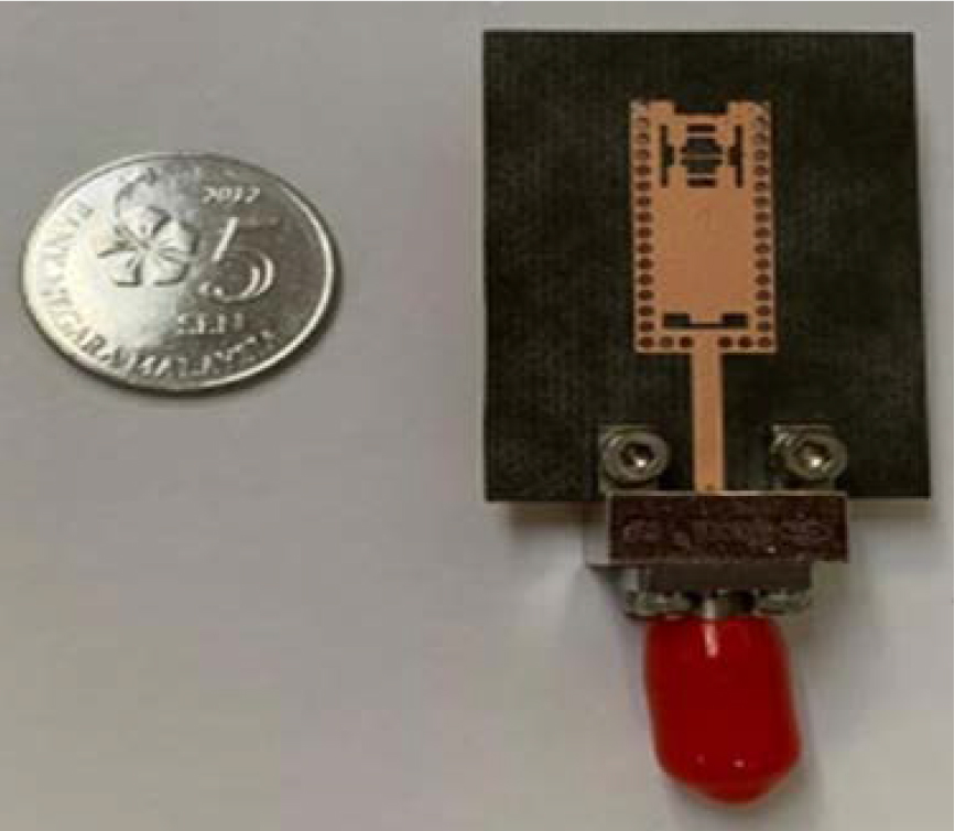
Figure 6: The fabricated SIW antenna.
The structure (prototype) of the proposed antenna design has been fabricated through standard single-layer PCB process, as shown in Figure 6, whereas their corresponding simulated and measured |S11| are plotted. The antenna has only one port working as a feeder, and both the simulated and measured results indicate that a good impedance match is achieved when the dual-band 26 to 28 GHz is under the criteria of 10 dB, for both selected prototypes.
IV. SIMULATION AND FABRICATION RESULTS
Figure 7 shows the comparison between the simulated and measured reflection coefficients of the antenna structure in different forms. Through the different design of antenna structure, the authors anticipate getting S11 of less than 10 dB over high frequency and suitable bandwidth. Both results demonstrate that the reflection coefficient stayed below 10 dB at 26 GHz.
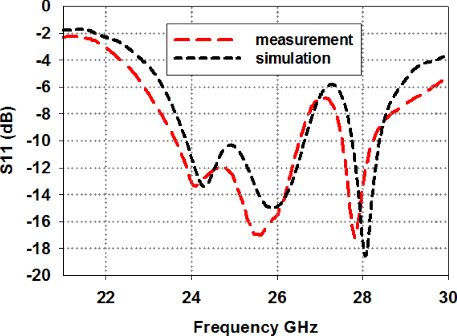
Figure 7: Simulated and measured S11 of the main structure which has slot A and B with diameter of vias 0.8 mm.
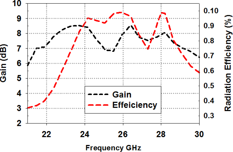
Figure 8: Gain and efficiency performance.
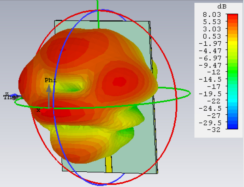
Figure 9: Simulated 3D radiation pattern of the main structure.
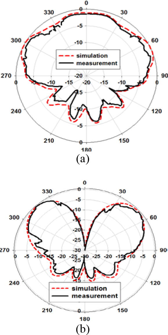
Figure 10: Simulated and measured 2D radiation pattern (polar) for (a) E-plane and (b) H-plane at 26 GHz.
Next, Figure 8 shows the measured efficiency and gain performance of the front-end module. The measured gains of the front-end module have frequency dependency from 180 to 180, when the line is a curve fitting result. The fitting curve has the center frequency of about 26 GHz, and the SIW antenna achieved gains of 8 dB at 26 GHz and 8.03 dB at 28 GHz.
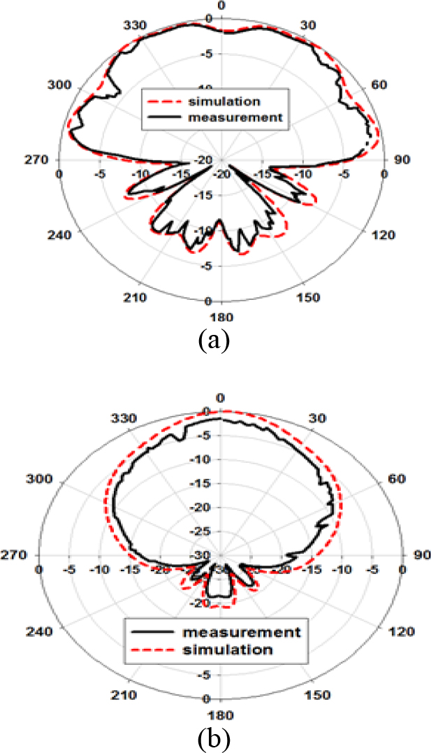
Figure 11: Simulated and measured 2D radiation patterns (polar) for (a) E-plane and (b) H-plane at 28 GHz.
Normally, the radiation pattern of the antenna will take shape from the edges of the patch, but for SIW, the majority comes from the slots of the main structure as shown in the simulated 3D radiation pattern in Figure 9. The lengths of all slots were around 4.5 mm. The results proved that the width of the slots is suitable to achieve dual-band at millimeter wave and suitable for 5G applications.
The simulated E-plane and H-plane patterns computed at 26 and 28 GHz are presented in Figures 10 and 11. Figure 10 shows the comparison between the simulated and measured radiation pattern in E- and H-planes which comes from (slot A) radiating at 26 GHz. Meanwhile, Figure 11 indicates the comparison between the simulated and measured radiation pattern coming from (slot B) which radiates at 28 GHz. From 2D radiation (polar), the shape of the main beam can be visualized. This is one of the requirements for 5Gapplication.
Due to the difference in the slot lengths, two different resonant modes with perturbed fields are excited within the SIW. Slot A, having longer slot length, radiated at 26 GHz and slot B at 28 GHz. These phenomena can be better understood with the help of surface current distribution on the top surface of the antenna at two resonant frequencies. Figure 12 shows that the surface current density becomes dominant on the lower half of the antenna and is mostly concentrated around the boundary of slot B. However, the surface current is almost negligible in the vicinity of slot A. It can be explained in a similar fashion, where surface current is mostly concentrated along the boundary of slot B.
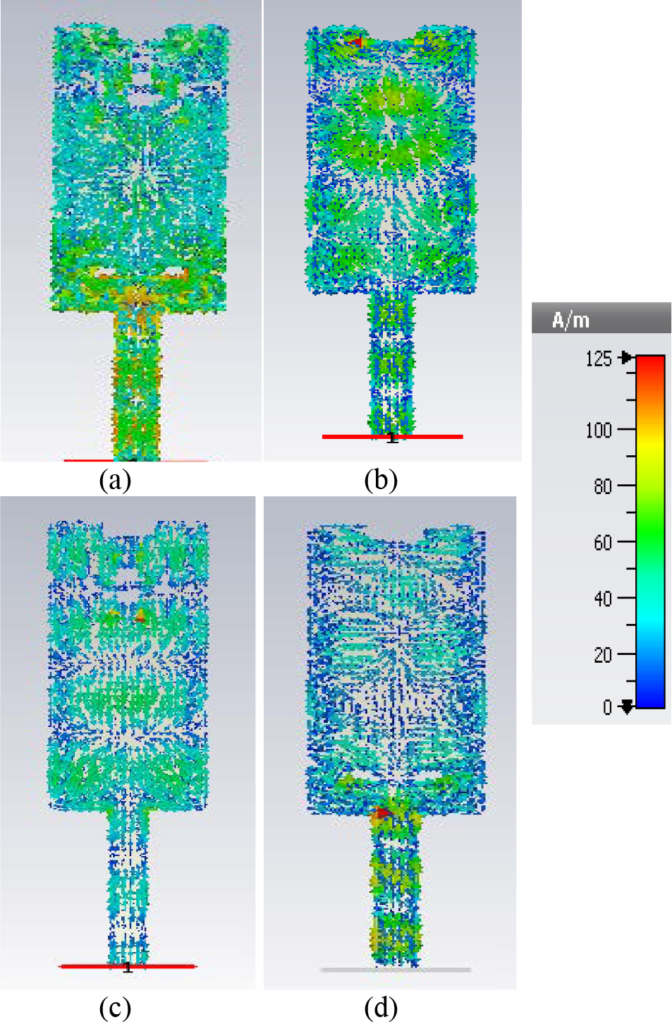
Figure 12: Simulated current distributions on the SIW surface of the surface current when (a) design with slots A and B, (b) design without slots, (c) design with slot A, and (d) design with slot B.
A comparison between the proposed design and previous works on dual frequency band millimeter-wave antennas is carried out in Table 2.
Table 2: Comparison between this work and some previous dual-frequency/-band millimeter-wave
| Ref. | Center freq. (GHz) | BW (GHz) | Gain (dB) | No. element |
| 11 | 28/38 | 20.4/2.64 | 13.2/14.6 | 2 2 |
| 12 | 37.5/47 | 1.1/1.4 | 5.0/5.7 | 1 |
| 13 | 2.45/5.19 | 0.2/0.5 | 5.02/4.09 | 1 |
| 14 | 21/26 | 0.7/0.8 | 16/17.4 | 3 1 |
| This work | 26/28 | 2.8/0. 6 | 8/8.03 | 1 |
V. CONCLUSION
SIW antenna with slots is presented in this work. The antenna is meant to prove the concept of SIW antennas performance to be followed for millimeter-wave applications. Roger RT 5880 substrate is suitable for higher frequency because of the loss. Suitable width of slots and patch were identified to achieve better results of the 5G application with high gain and directivity with dual-band frequency. Gain that was achieved at 26-28 GHz are 8-8.03 dB, the directivity of dual-band is 8.18-8.22 dB, and also design provides sufficient impedance bandwidths at 2.8-0.6 GHz.
ACKNOWLEDGMENT
The authors would like to thank the Ministry of Higher Education (MOHE), School of Postgraduate Studies (SPS), Research Management Centre, Advanced RF and Microwave Research Group, School of Electrical Engineering, and Universiti Teknologi Malaysia (UTM), Johor Bahru, for the support of the research under Grant 09G19/06G15/04G65.
REFERENCES
[1] X. C. Lin and C. C. Yu, “A dual-band CPW-fed inductive slot-monopole hybrid antenna,” IEEE Transactions on Antennas and Propagation, vol. 56, no. 1, pp. 282-285, 2008.
[2] Y. Ding and K. W. Leung, “On the dual-band DRA-slot hybrid antenna,” IEEE Transactions on Antennas and Propagation, vol. 57, no. 3, pp. 624-630, 2009.
[3] I. Yeom, J. M. Kim, and C. W. Jung, “Dual-band slot-coupled patch antenna with broad bandwidth and high directivity for WLAN access point,” Electronics Letters, vol. 50, no. 10, pp. 726-728,2014.
[4] X. Zhang, Y. Chen, Y. Xie, and L. Liu, “An improved E-plane waveguide power divider design for 94GHz dual-pyramidal horn antenna,” The Applied Computational Electromagnetics Society (ACES) Journal, pp. 1897-1903, 2019.
[5] Y. M. Hussain, M. K. A. Rahim, N. A. Murad, H. O. Hanoosh, and H. H. Keriee, “Substrate integrated waveguide cavity slot antenna at millimeter wave for 5G application.” In 2021 International Symposium on Antennas and Propagation (ISAP). IEEE, pp. 1-2, Oct., 2021.
[6] Y. M. Hussein, M. K. A. Rahim, N. A. Murad, M. M. Jawad, H. O. Hanoosh, H. A. Majid, and H. H. Keriee, “Substrate integrated waveguide and microstrip antennas at 28 GHz,” Bulletin of Electrical Engineering and Informatics, vol. 9, no. 6, pp. 2462-2468, 2020.
[7] H. O. Hanoosh, M. K. A. Rahim, N. A. Murad, and Y. M. Hussein, “Multi-beams waveguide slot antennas at X-band for wireless communications systems,” The Applied Computational Electromagnetics Society (ACES) Journal, pp. 797-802, 2020.
[8] M. A. Rahim, I. M. Ibrahim, R. A. A. Kamaruddin, Z. Zakaria, and N. Hassim, “Characterization of microstrip patch array antenna at 28 GHz,” Journal of Telecommunication, Electronic and Computer Engineering (JTEC), vol. 9, no. (2-8), pp. 137-141, 2017.
[9] S. Moitra, A. K. Mukhopadhyay, and A. K. Bhattacharjee, “Ku-band substrate integrated waveguide (SIW) slot array antenna for next generation networks,” Global Journal of Computer Science and Technology, 2013.
[10] M. Bozzi, A. Georgiadis, and K. Wu, “Review of substrate-integrated waveguide circuits and antennas,” IET Microwaves, Antennas & Propagation, vol. 5, no. 8, pp. 909-920, 2011.
[11] T. Hong, Z. Zhao, W. Jiang, S. Xia, Y. Liu, and S. Gong, “Dual-band SIW cavity-backed slot array using TM 020 and TM 120 modes for 5G applications,” IEEE Transactions on Antennas and Propagation, vol. 67, no. 5, pp. 3490-3495, 2019.
[12] Q. Wu, J. Yin, C. Yu, H. Wang, and W. Hong, “Low-profile millimeter-wave SIW cavity-backed dual-band circularly polarized antenna,” IEEE Transactions on Antennas and Propagation, vol. 65, no. 12, pp. 7310-7315, 2017.
[13] Y. Ding and K. W. Leung, “On the dual-band DRA-slot hybrid antenna,” IEEE Transactions on Antennas and Propagation, vol. 57, no. 3, pp. 624-630, 2009.
[14] W. Li, K. Da Xu, X. Tang, Y. Yang, Y. Liu, and Q. H. Liu, “Substrate integrated waveguide cavity-backed slot Array antenna using high-order radiation modes for dual-band applications in $ K $-band,” IEEE Transactions on Antennas and Propagation, vol. 65, no. 9, pp. 4556-4565, 2017.
BIOGRAPHIES

Yaqdhan Mahmood Hussein was born in Samawah, Iraq, in 1991. He received the B.S. degree in computer techniques engineering in 2014-2015 from Islamic University College, Najaf city, and the M.S. degree in electronic engineering (telecommunication system) from Universiti Teknikal Malaysia Melaka (UTeM), Malaysia, in 2018, respectively, and he is currently working toward the Ph.D. degree in electronic engineering with Universiti Teknologi Malaysia (UTM), Johor Bahru city. His current research interests include millimeter-wave antennas, base station antennas, and SIW technology with butler matrix.

Mohamad Kamal A. Rahim received the B.Eng. degree in electrical & electronics from the University of Strathclyde, U.K., in 1987. He received the M.Eng. degree in science from the University of New South Wales, Australia, in 1992 and the Ph.D. degree in electrical engineering from University of Birmingham, U.K., in 2003.
He is a Professor in RF & Microwave and Antenna at School of Electrical Engineering, Universiti Teknologi Malaysia. His research interest includes the areas of radio frequency, microwave and antennas.
He has been awarded with top research publication in 2015, 2017, and 2020. In 2018, he was honored as “Tokoh Penyelidik” at CITRA KARISMA UTM, and in the same year, he was awarded with Top Research Scientist Malaysia (TRSM) award by Academy Science of Malaysia.

Noor Asniza Murad received her first degree, Bachelor of Engineering (Electrical – Telecommunications), in 2001 from Universiti Teknologi Malaysia (UTM). Shortly after graduation, she served UTM as a tutor. She graduated with Master of Engineering (Electrical) in 2003 from the same university and has been appointed as a Lecturer in April 2003. She joined Emerging Device Technology Group, University of Birmingham, U.K., and obtained the Ph.D. degree in 2011 for research on micromachined millimeterwave circuits. She attached to HID GLOBAL Sdn Bhd for one year under Research and Development specifically working on RFID tag design, testing, and development. Her research interests include antenna design for RF and microwave communication systems, millimeter-wave circuits design, RFID, and antenna beamforming. Currently, she is a senior member of IEEE (MIEEE), MBOT Professional Technologist, and an Associate Professor with the School of Electrical Engineering, Universiti Teknologi Malaysia (UTM).

Hatem Oday Hatem (H. O. Hanoosh) was born in Samawah, Iraq, in 1991. He received the B.S. degree in computer techniques engineering in 2014-2015 from Islamic University College, Najaf City. He received the M.S. degree in electronic engineering (telecommunication system) from University Technical Malaysia Melaka (UTEM), Malaysia, in 2018, respectively, and he is currently working toward the Ph.D. degree in electronic engineering with University Technology Malaysia (UTM), Johor Bahru City. His current research interests include millimeter-wave antennas, base station antennas, and waveguide slot antennas.

Norsaidah Binti Muhamad Nadzir was born on March 12, 1993. She received the Master of Philosophy degree in electrical engineering from Universiti Teknologi Malaysia, Johor Bahru, Malaysia, in 2019. She is currently working toward the Doctor of Philosophy degree in electrical engineering with the same university. Her research interests include radio frequency identification (RFID) systems, RFID antennas, and compact millimeter-wave antennas. Her focus is on millimeter wave antenna with beamforming devices.
ACES JOURNAL, Vol. 37, No. 4, 478–484.
doi: 10.13052/2022.ACES.J.370413
© 2021 River Publishers