Dynamic Force Calculation and Experimental Verification of Axial Bearings
Mingqi Wang, Jingjing Zhao, Xingnan Liu, Ni Mo, and Zhengang Shi*
Institute of Nuclear and New Energy Technology, Tsinghua University, Beijing 100084, China, Collaborative Innovation Center of Advanced Nuclear Energy Technology, Beijing 100084, China, The Key Laboratory of Advanced Reactor Engineering and Safety, Ministry of Education, Beijing 100084, China
wang-mq19@mails.tsinghua.edu.cn, zhao-jj@tsinghua.edu.cn, liuxingnan@tsinghua.edu.cn, moni@tsinghua.edu.cn, shizg@tsinghua.edu.cn (Corresponding author)*
Submitted On: June 7, 2021; Accepted On: March 21, 2022
Abstract
The axial bearing does not contain a laminated piece; so its dynamic performance is poor and often does not meet the load requirements. To accurately assess axial bearing performances during the design stage, it is necessary to accurately calculate the dynamic characteristics of the bearing, including amplitude, phase, and other parameters. Traditional studies have generally used the magnetic circuit method (MCM) or the finite element method (FEM) to analyze the dynamic performance of bearings, and few experimental measurements are carried out. Some experiments use a Guess meter to measure the magnetic field at local locations without directly measuring the electromagnetic force. In this paper, the dynamic force of axial bearing is measured by experiments, and the finite element calculation with Ansys Maxwell is carried out to study the influence of the gap, resonance, and other factors on the electromagnetic force. The comparison reveals a significant error in the calculation method using the initial gap because the gap between the stator and rotor changes with the dynamic force in the experiment. In this paper, the calculation method of “analyzing the dynamic performance of the bearing with the actual gap after the DC component is energized as the calculation gap” is proposed, which significantly reduces the calculation error and can ensure that the calculation error of amplitude and phase within 100 Hz is less than 5%. The method is of great significance for the engineering application of axial electromagneticbearings.
Keywords: Axial bearing dynamic performance, gap, resonance.
I. INTRODUCTION
Active magnetic bearings are widely used in various fields such as turbomachinery, vacuum systems, and high-temperature environments due to their advantages of no contact, no lubrication, and low loss [1]. The radial and axial bearings will control 5 degrees of freedom of the rotor, including radial and axial rotation and translation, respectively. Working in a changing magnetic field induces eddy currents in the stator and rotor, which will bring energy loss and affect the dynamic electromagnetic force and dynamic stiffness coefficient, thus affecting the dynamic characteristics of the system. However, considering the rotor strength and the feasibility of the manufacturing process, the stator and rotor of axial bearings are usually made of solid carbon steel or alloy steel [2], whose dynamic performance is poor and often fails to meet the load requirements. To accurately evaluate the dynamic characteristics of the axial bearing in the design stage, the dynamic forces in the axial direction, including parameters such as amplitude and phase, need to be accurately calculated. The magnetic field distribution around the rotor is far from the sinusoidal model, and its Fourier series expression will include many harmonics of the rotation angle. Moreover, magnetic bearings are generally driven by switching power amplifiers. The high-frequency ripple current caused by the switching power amplifiers and the dynamic control current with higher frequency will induce strong eddy currents in the bearing stator and thrust disc. Due to the skin effect of eddy current, mainly high-order harmonics will be driven out from the stack. The dynamic performance of axial bearings is challenging to evaluate accurately [3].
To study the dynamic performance of axial bearings, many scholars mainly use magnetic circuit method (MCM) and finite element method (FEM) to analyze and have achieved some results. Takeshi [4] uses FEM to analyze the eddy current problem when a simple magnetic bearing model uses solid steel as shaft material. Feeley et al. [5] present a simple dynamic model of eddy currents in a magnetic actuator, using the 2D eddy current equation to solve the uneven distribution of air gap magnetic field caused by eddy currents. Zhu et al. [2] develop an analytic model for a nonlaminated cylindrical magnetic actuator including eddy current effects by using the MCM. The frequency response of the analytic model is compared with the results of FEM. Sun et al. [6] present a linear model including eddy current effects for a typical active magnetic thrust bearing (AMTB) and calculate the dynamic current stiffness and displacement stiffness using analytical method and transient finite element (FE) analysis. Zhu et al. [7] decompose the structure of the solid rotor actuator into the essential ring element and establish a magnetoresistance model considering the eddy current effect by solving the electromagnetic field within each essential element. Tian et al. [8] propose a fractional differential equation (FDE) model of the switching ripple current (SRC) considering the effects of eddy current and obtain a numerical solution by a predictor-corrector algorithm. The presented model can be applied to the studies of self-sensing of nonlaminated magnetic bearings. Han et al. [9] establish the dynamic factor models affected by the eddy currents for the hybrid thrust magnetic bearing (HTMB) with permanent magnets and subsidiary air gap, and the model’s accuracy is verified by transient FE analysis. Henry et al. [10] mathematically formulate the problem of maximizing axial magnetic bearing actuator bandwidth through the choice of geometric and materialproperties.
However, the results of theoretical calculations and software simulations often differ significantly from actual engineering experiments, and there are few actual engineering experiments on dynamic electromagnetic force measurement of axial bearings.
Meeker et al. [11] formulate an augmented circuit model to account for eddy current, leakage, and fringing effects in radial active magnetic bearing. However, no analysis has been performed for axial bearing. Khoo et al. [12] propose a new concept, an active magnetic bearing with multiple parallel discs. The concept aims to solve the problem that the load-carrying capacity of traditional active magnetic bearings is limited by the saturation of magnetic flux density in iron. Yang et al. [13] present a new thrust actuator design for magnetic bearings. The actuator can produce high thrust but low radial attraction force. The actuator force characteristics are analyzed using FE analysis. Experimental verifications are also performed. Henry et al. [14] couple the nonlinear electromagnetic force measured in the experiment to a dynamic model. The Guess meter is used to measure the magnetic field at local locations but cannot directly measure the electromagnetic force. Wang et al. [15] propose a method to improve the measurement accuracy of imbalance identification. It uses a controllable electromagnet to generate the controllable electromagnetic force to attenuate the unbalance vibration synchronously. The equivalent magnetic circuit model of the electromagnet is established, and the relationship between the coil current and the dynamic electromagnetic force is analyzed by the FEM. Xu et al. [16] build a test platform for push-pull characteristics of a double-actuator electromechanical converter to test and analyze its static and dynamiccharacteristics.
To accurately analyze the axial bearing’s dynamic characteristics: the dynamic force of the axial bearing at different AC frequencies, including parameters such as amplitude and phase, which reflect the real dynamic performance of the axial bearing in actual engineering experiments. Then use Ansys Maxwell to perform FE simulation to seek a simulation model that can truly reflect the actual experimental results. Experiments show that there are apparent errors in the method of calculating the dynamic force of the axial bearing by using the initial measurement of the gap because the stator and rotor gap will change with the dynamic force. In this paper, the calculation method of “analyzing the dynamic performance of the bearing with the actual gap after the DC component is energized as the calculation gap” is proposed. Considering the resonance of the table, we can calculate the dynamic characteristics of the axial bearing, which can significantly reduce the calculation error and ensure that the calculation error of amplitude and phase within 100 Hz is less than 5%. The above methods are of great significance to the engineering application of axial electromagnetic bearings.
II. INTRODUCTION TO THE EXPERIMENT
Theoretically, ignoring the core’s magnetization and assuming that there is no electrical energy exchange between the coil and the power supply, assuming that the magnetic flux density remains constant. According to the principle of virtual displacement, the magnitude of the static axial force F generated by the axial bearing is equal to the partial derivative of the field energy W to the displacement of the core s:
| (1) |
where represents permeability of vacuum, A and n are, respectively, the air gap area and winding turns of the core, i represents the control currents, and s represents the displacement of the core. The secondary term coefficients indicate the nonlinear relationship between the electromagnetic force and the displacement and control currents. In addition, the dynamic unbalance of the rotor, the gyroscopic effect of the rigid rotor, and the flexible rotor multi-order modes and vibration patterns also cause the above nonlinear relationship.
The rotor core is repeatedly magnetized several times in one revolution (determined by the axial bearing structure) during rotor rotation. The dynamic characteristics are nonlinear, with alternating currents of different frequencies passing through the windings. Moreover, the actual structure of the bearing is complex, and there are other accidental factors. The FE analysis alone is not enough to correctly reflect the actual dynamic characteristics of the bearing. Therefore, the dynamic force measurement experiments of the solid structure axial bearings under different AC frequencies are carried out in this paper.
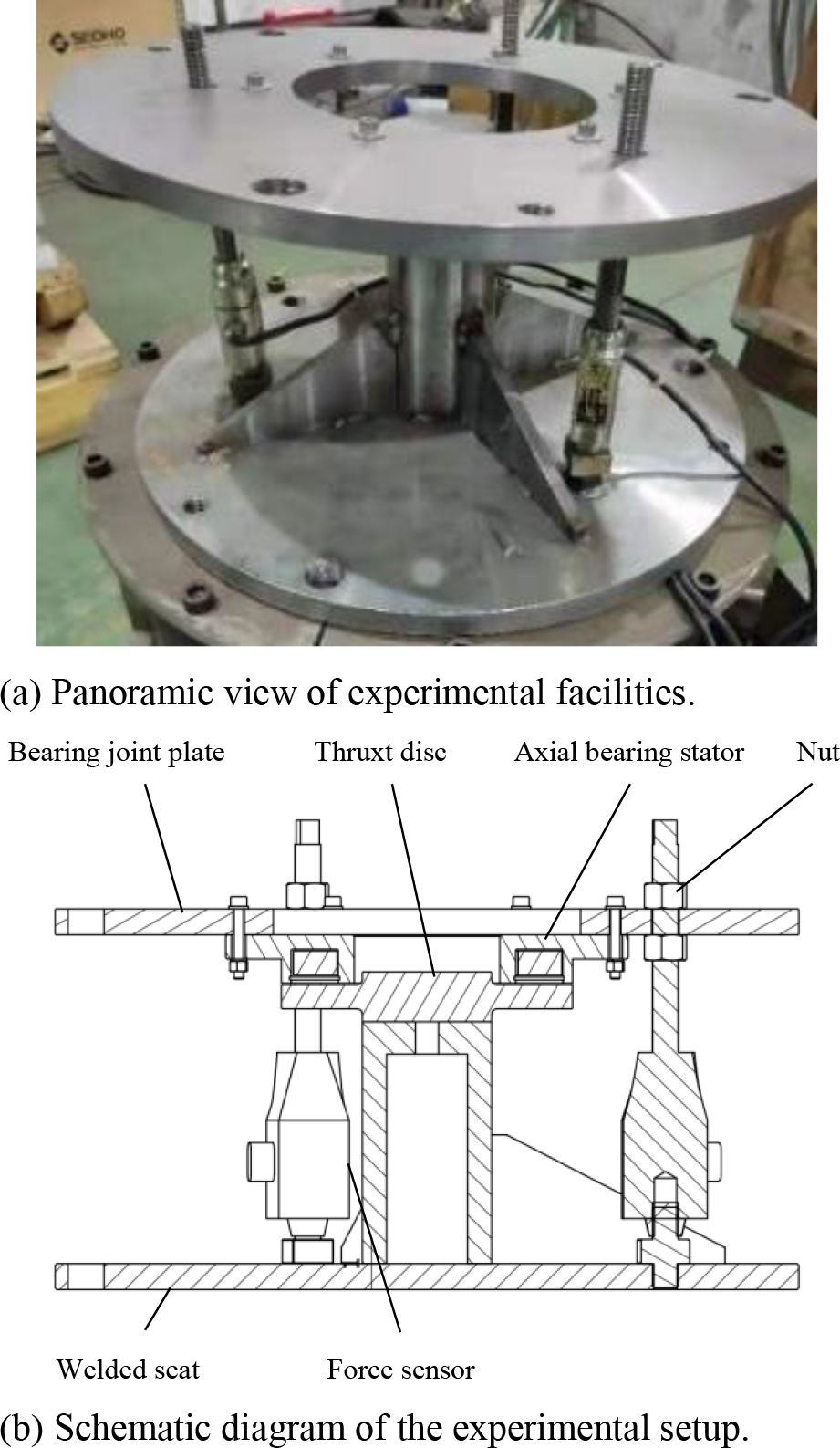
Figure 1: Schematic diagram of the experimental setup for dynamic force measurement of solid structure axial bearings.

Figure 2: CL-YB-13T/100kg force measuring sensor.
The schematic diagram of the experimental setup for dynamic force measurement of solid structure axial bearings is shown in Figure 1. The thrust disk is fixed on the base, and the axial bearing stator is connected to the base through three CL-YB-13T/100kg force measuring sensors. A nut adjusts the gap between stator and disk, and a stopper can measure the size of the gap with an error range of 0.02 mm. The axial force between the stator and rotor is obtained from the combined force of the three force sensors.
Figure 2 shows the CL-YB-13T/100kg force sensor. The output signal of the measurement sensor can be obtained from the peak-to-peak value of the force sensor voltage and the peak-to-peak value of the sensor current. According to the relationship between the peak-to-peak value of sensor voltage and axial force, the peak-to-peak value of the actual axial force of the device at each moment can be obtained. In this paper, the environment is the atmosphere, and the room temperature is . The computer records the force signal through the force sensor, transmitter, and data acquisition card shown in Figure 2. The data sampling frequency is Hz. The initial gap of bearing is adjusted to 0.5 mm, and 5-A DC with an AC of amplitude 2 A is passed into the winding. The winding temperature is C before the experiment, and the AC frequency is set to vary from 10 to 1000 Hz to record the force transducer signal. According to the transducer’s signal characteristics, the axial bearing’s dynamic performance can be obtained, that is, the peak-to-peak value and average phase of the dynamic force. Similarly, a total of four sets of experiments with different initial gaps and different winding currents are subsequently carried out. To avoid the contingency of experimental measurement and improve the accuracy of the experiment, we measured each group twice. Figure 3 shows the peak-to-peak values of the electromagnetic force measured by force measuring sensor concerning the input AC frequency under different experimental conditions. As shown in Figure 3 (a), the measurement results of Group 1 and Group 2 were the same, and the same repeated experiments were also carried out for other groups.
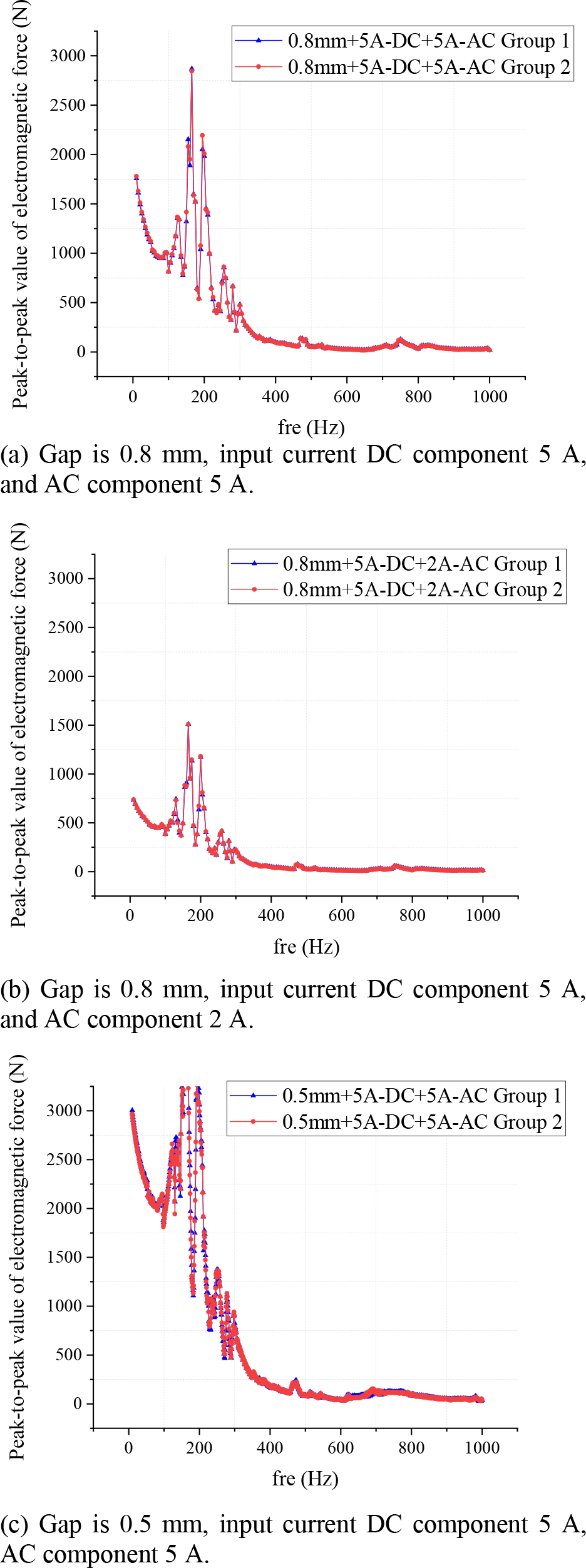
Figure 3: Peak-to-peak value of dynamic electromagnetic force for experimental measurement.
It can be concluded that the peak-to-peak value of the electromagnetic force tends to decrease gradually with the increase of the AC frequency. In the range of 400–1000 Hz, the peak-to-peak value of electromagnetic force is in the range of less than 200 N. The smaller the stator-rotor gap of the axial bearing, the larger the amplitude of the AC component of the input current in the winding, the larger the peak-to-peak value of electromagnetic force, which is more evident in the range of 0–400 Hz AC frequency, and there is no significant difference in the range of 400–1000 Hz. In the range of 100–200 Hz, the peak-to-peak value of electromagnetic force has significant fluctuations, which may be related to the self-oscillation frequency of the experimental bearing itself. The peak-to-peak value of electromagnetic force at the corresponding multiplier frequency also has certain fluctuation. Figure 4 shows the average phase between the electromagnetic force measured by the force measuring sensor and the input current under different experimental conditions as a variation of the input AC frequency.
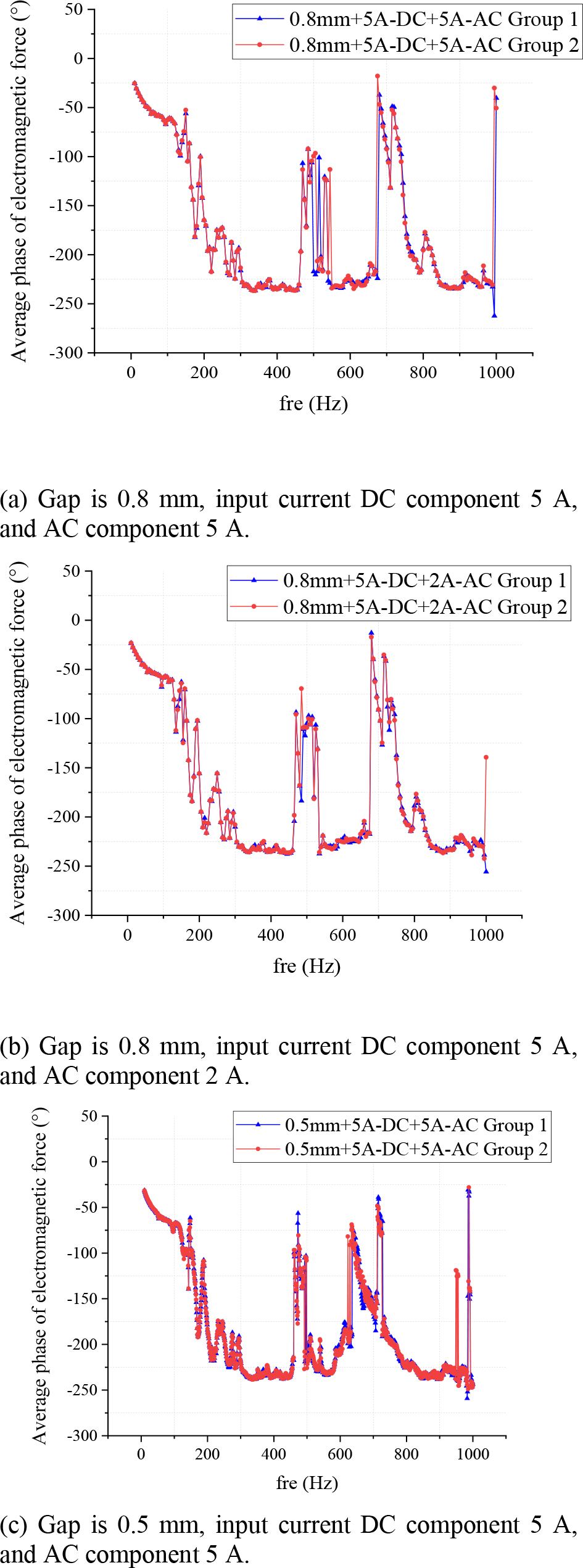
Figure 4: The average phase between dynamic electromagnetic force and the input current was measured experimentally.
It can be concluded that the average phase of the electromagnetic force generally tends to decrease gradually as the AC frequency increases, and this pattern is well maintained at 0–400 Hz. Due to the influence of the overall vibration, natural vibration frequency, and measurement error of the test structure, the average phase of electromagnetic force fluctuates in the range of 0–400 Hz. The influence is especially obvious in the range of 400–1000 Hz, where the average phase of the electromagnetic force has significant fluctuations. It can be seen from the results in the figure that the gap between stator and rotor of the axial bearing and the amplitude of the AC component of the input current in the winding has little effect on the average phase of the electromagnetic force.
III. FINITE ELEMENT CALCULATION MODEL AND CALCULATION METHOD
The FEM is used to analyze the dynamic harmonic field of the electromagnetic axial bearing. When studying the dynamic characteristics of axial bearings, it is necessary to simplify the actual problem studied, introduce reasonable assumptions, and turn the original problem into a solvable mathematical problem. Introduce the following assumptions related to the premises:
1. Ignore the temperature effect of conductor resistivity and assume that the conductor resistivity remains constant.
2. Reduce the actual three-dimensional field problem to a two-dimensional axisymmetric field problem.
3. Ignore the hysteresis effect of the material and the leakage effect in the loop.
4. The gap length between the stator and rotor is uniform.
Table 1: Basic parameters of the axial bearing model
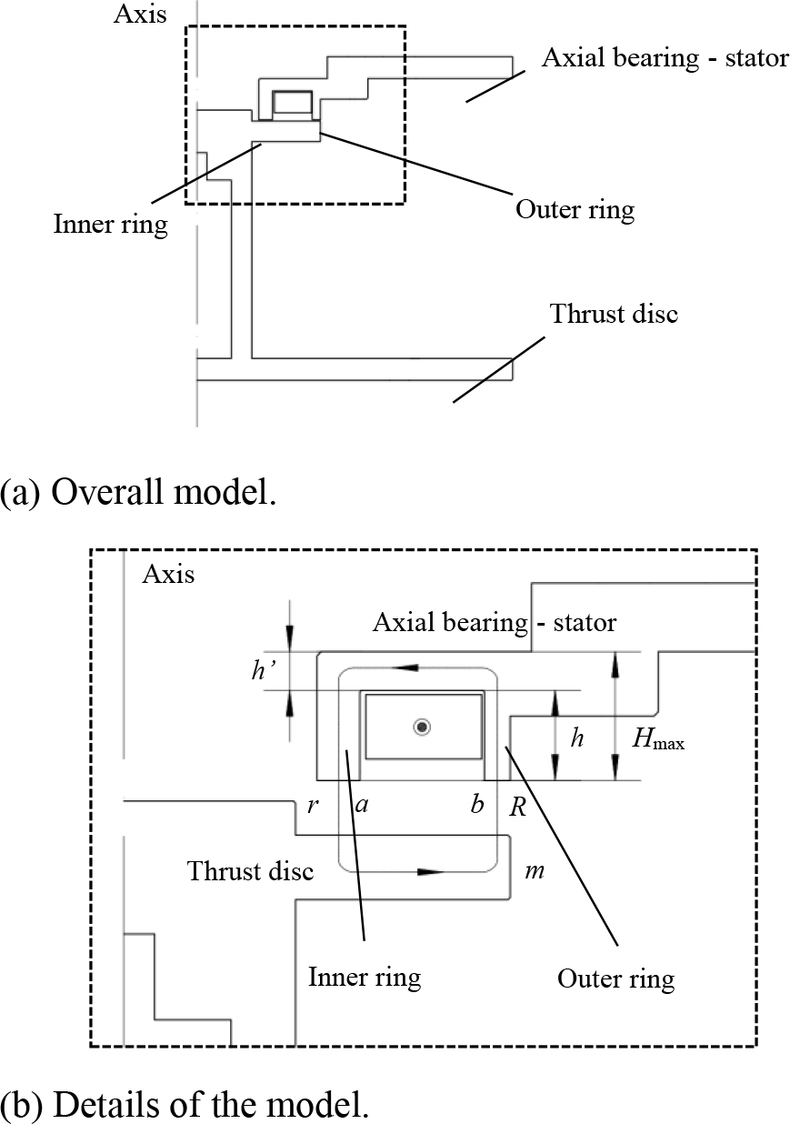
Figure 5: Simplified model of the axial bearing.
The axial bearing of the experimental device is a circumferentially symmetric structure, and the loads in all directions can be regarded as uniform. Therefore, the axisymmetric field is used to calculate the FE solution using Ansys Maxwell. For this purpose, an FE model is established, as shown in Figure 5. In the selection of the size of the current winding, since the software can directly input the number of turns of the coil, the size of the model has no strict size. Just enter the number of turns to meet the actual working conditions. Figure 5 shows the simplified model of the experimental setup, and Table 1 shows the model’s parameters.
For the electromagnetic axial bearing model, the coils are wound from copper wire, and the material used for the thrust disc and stator is 45 steel, respectively. The rest is air. Table 2 gives the relevant materials’ required resistivity and relative magnetic permeability.
Time-varying currents flowing in a conductor produce a time-varying magnetic field in planes perpendicular to the conductor. In turn, this magnetic field induces eddy currents in the source conductor and any other conductor parallel to it. Eddy currents are calculated by solving for A and in the field equation:
| (2) |
where A represents the magnetic vector potential, represents the electric scalar potential, is the absolute magnetic permeability, is the angular frequency at which all quantities are oscillating, is the conductivity, and is the absolute permittivity. The current plot of flux lines produced by eddy currents computed in a structure by Ansys Maxwell is shown below.
Table 2: Simulation parameters of electromagnetism of axial bearing
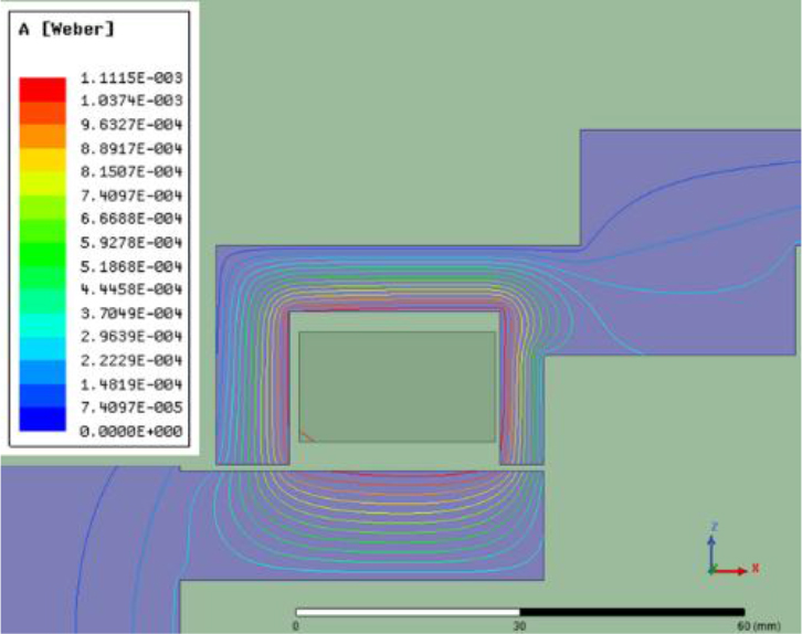
Figure 6: Magnetic lines of force and magnetic field distribution of the test axial bearing.
Substitute the structural parameters into Ansys Maxwell and run it to change the current frequency of the input AC to obtain the dynamic characteristics of the axial bearing, such as electromagnetic force and phase under various frequency excitations. Differences between Ansys Maxwell calculations and experimental measurements are then analyzed.
IV. COMPARISON OF EXPERIMENTAL DATA AND CALCULATIONS
A. Static electromagnetic force and magnetic field conditions
The component of the Lorentz force due to current in a magnetic field is
| (3) |
where J represents the current density and B represents the magnetic flux density. Using Ansys Maxwell analysis, the gap between the stator and the thrust disk is 0.5 and 0.8 mm, and the comparison between the measured static force and the software calculated electromagnetic force when the input current of the experimental axial bearing is 1–10 A as shown in Figure 7.
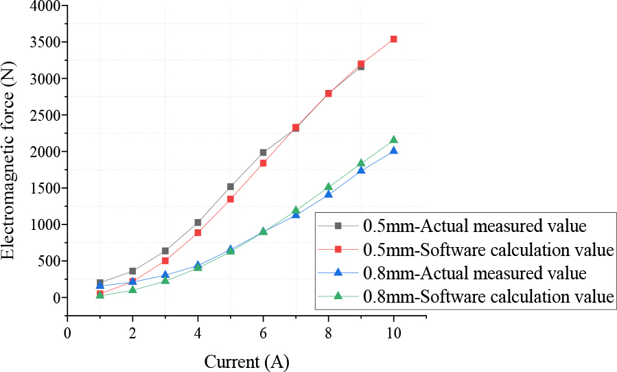
Figure 7: Comparison of measured static force and software calculated electromagnetic force.
While the current increases to a certain extent, the growth rate of the electromagnetic force decreases significantly, mainly due to the rise of the magnetic leakage flux, and the material reaches its magnetizing saturation. It is shown that the software simulation results are in good agreement with the experimental measurement results when calculating the static electromagnetic force. The static electromagnetic force becomes more significant with the increasing amplitude of the input DC in the winding. Meanwhile, the smaller the gap between the axial bearing stator and rotor, the larger the value of static electromagneticforce.
B. Comparison of experimental measurement and simulation of dynamic electromagnetic force
The virtual force in an eddy current problem is computed the same way as virtual force in a magneto-static problem. The only difference is that the average value of force over time is computed - not the instantaneous force at a given time. The time-averaged (or DC) force and AC force can be determined by
| (4) |
And instantaneous force is the sum of the time-averaged (or DC) force and the AC force:
| (5) |
The gap between the bearing stator and the thrust disk is set to 0.8 mm, and a 5-A DC and an AC of 2-A amplitude are passed into the winding. The calculation time is set to 1.5 s, the calculation step is 0.0005 s, and the AC frequency is varied from 10 to 100 Hz. Figure 8 shows a comparison between simulation calculation result and experimental measurement. The overall change trend of the two is consistent, and the electromagnetic force tends to decrease with the increase of the AC frequency. The causes of the errors are discussed below.
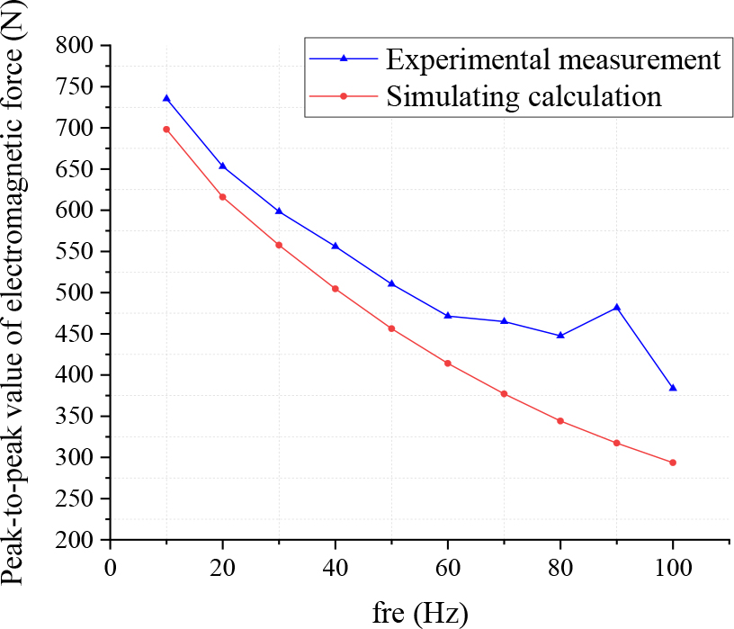
Figure 8: Gap 0.8 mm, 5 A DC + 5 A AC simulation calculation compared with experimental measurement.
C. Error source: The gap between stator and thrust disk
Since the input current in the winding has both DC and AC components, the instantaneous value of the current in the winding is different at different moments, which causes the change of the transient electromagnetic force on the thrust disk at other moments. The gap between the stator and the thrust plate changes dynamically. Figure 9 shows the magnitude of static electromagnetic force calculated for different gaps at 100-Hz frequency. It can be concluded that the gap has a significant influence on the magnitude of axial electromagnetic force. The smaller the air gap, the larger the electromagnetic force. The gap and static electromagnetic force are approximately linearly distributed.
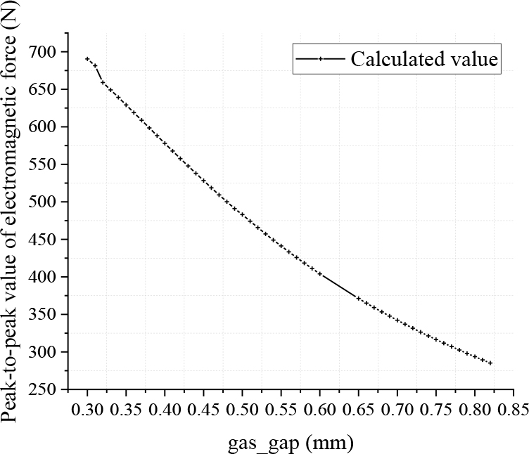
Figure 9: Effect of the gap on the magnitude of static axial electromagnetic force.
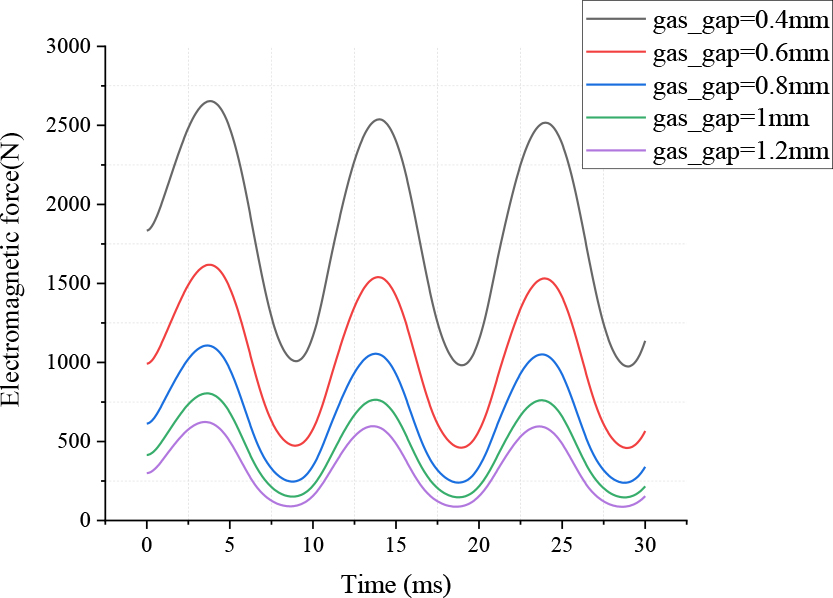
Figure 10: Effect of the gap on the magnitude of the dynamic axial electromagnetic force.
The variation of dynamic electromagnetic force under different gaps with the same excitation current is shown in Figure 10. Force oscillates at twice the frequency of the source current and magnetic field:
| (6) |
where f is the frequency of the force, f is the frequency of the source current and magnetic field, and T is the period of the force. The smaller the air gap, the larger the generated electromagnetic force, but the electromagnetic force waveform (half-sine wave) remains constantly.
If the actual value of the air gap between stator and thrust disk is considered in the simulation calculation, the calculation process is more complicated and time-consuming. Therefore, this paper will use the actual gap after the DC component is electrified as the calculation gap to analyze the dynamic performance of bearings. This means that applies a DC, which has the magnitude of the experiment’s DC to the winding, and the actual gap between the stator and the thrust disk is measured at this time as the calculated gap.
The test clearance is measured by hand, and there may be some errors. To verify the accuracy of the measurement results, the axial bearing stiffness is calculated by measuring multiple sets of data using the characteristic of constant axial bearing stiffness. The accuracy of the measured gap values is verified by applying a DC with the magnitude of the experimental DC component to the winding. The axial bearing stiffness is as follows:
| (7) |
As shown in Table 3, the stiffness values are calculated separately for each case.
Table 3: Effect of gap variation on stiffness for different currents
The calculated values of the corresponding static force stiffness were mainly within the same range of values. It is considered that the above manual measurement gap results are more reliable. The gap between the stator and the thrust disk is held to be 0.5 mm, and 0.43 mm is used as the calculated gap for the Ansys Maxwell calculation when the current in the winding is 5-A DC component + 2 A/5 A AC components; the gap is 0.8 mm, and 0.755 mm is used as the calculated gap when the current in the winding is 5-A DC component + 2 A/5 A AC component.
D. Error source: The resonant frequency of the axial bearing itself and other
Due to the existence of resonant frequencies in the experimental bearing itself, the actual experimental measurement results have certain fluctuations. To compare with the simulation results, the experimental results should be somewhat smoothed and the AC frequencies in the resonant frequency range should be considered separately. In addition, the response frequency of the force transducer used in the experiment is less than 500 Hz, which will lead to a larger measurement error of the phase and amplitude of the electromagnetic force in the larger AC frequency range. The calculated result of the electromagnetic force is only close to the measurement result in 100 Hz.
E. Comparison of electromagnetic force peak-to-peak experiment and simulation results
Based on the above error source analysis, the peak-to-peak value of electromagnetic force is simulated and the calculation result is shown in Figure 11.
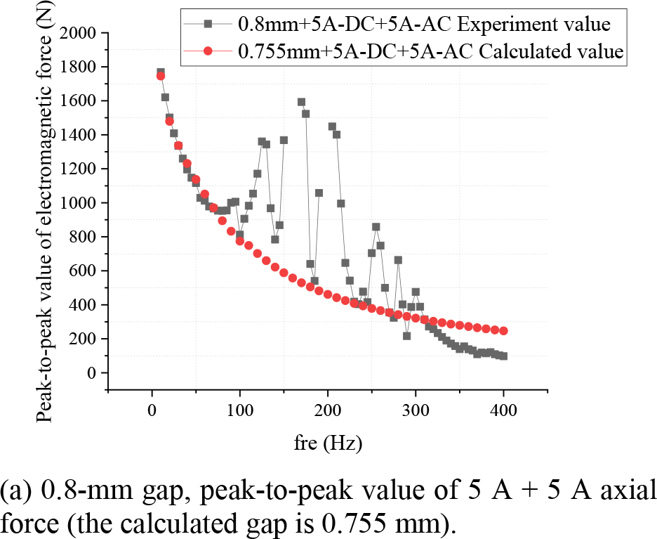
Figure 11: Comparison between the experimental results and simulation results of electromagnetic force peak-to-peak value.
The calculation error of electromagnetic force amplitude within 100 Hz is less than 5%. The amplitude of electromagnetic force within 100–300 Hz is influenced by the resonant frequency of the axial bearing itself, and the experimental results differ greatly from the simulation results. In the calculation range of more than 300 Hz, the experimental results are different from the simulation results due to the measurement error of the test force transducer and the simplification of the simulation model, but the overall trend of the two is the same. The simulation calculation results after certain error elimination are of great significance for the actual experimental measurement.
F. Comparison of experimental measurement and simulation of electromagnetic force mean phase
According to the experimental measurement diagram, the gap between the stator and rotor of the axial bearing has little effect on the average phase of the electromagnetic force. To further investigate the influence of the gap between the stator and rotor of the axial bearing on the average phase of the electromagnetic force, the influence on the average phase of the electromagnetic force at different gaps is calculated by using the software. Figure 13 shows the calculated values of the average phase of the electromagnetic force at different frequencies and gaps.
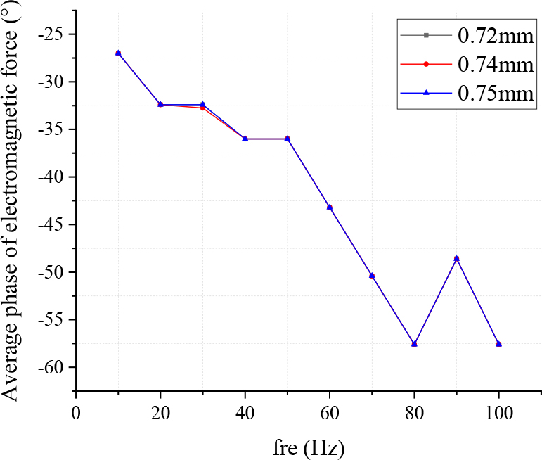
Figure 12: Effect on the average phase of electromagnetic force with different gaps.
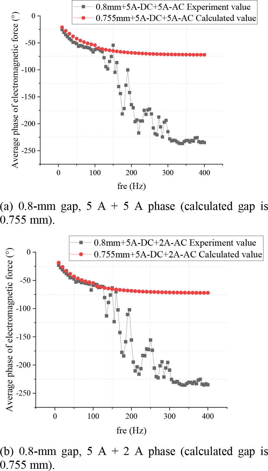
Figure 13: Comparison between the experimental results and simulation results of the electromagnetic force phase.
According to Figure 13, the phase difference between the axial bearing electromagnetic force and the input current is related to the AC frequency and has little relationship with the gap between the stator and the thrust disc. To further investigate the comparison between the simulation calculation results and the experimental results of the average phase of electromagnetic force after the above error analysis, the comparison between the simulation calculation results and the experimental results of the average phase of electromagnetic force at 0.8-mm gap is calculated by using Ansys Maxwell as shown in Figure 13.
The calculation error of the electromagnetic force phase is similar to its amplitude calculation. When the AC frequency is within 100 Hz, the error between the calculated simulation results and the experimental measurement is less than 5%. When the AC frequency in the circuit is greater than 100 Hz, the calculation results of the electromagnetic force phase deviate from the experimental measurement results due to resonance and measurement errors. The phase deviation between the electromagnetic force and the current may be reversed by 180 because of the limitation of the measuring instrument. The measurement error of the phase is not discussed in detail here. If this part of the deviation is considered, the actual measurement results of the phase and the simulation results will also have better compliance in a larger range of AC frequency. It can be seen that the simulation calculation results after eliminating certain errors are of great significance to the actual experimental measurement.
V. CONCLUSION
To accurately evaluate the axial bearing performance at the design stage and accurately calculate the dynamic performance of the bearing, including parameters such as amplitude and phase. This paper compares the differences between the experimental measurement results and the simulation results and finds that the simulation results are of good guidance for the actual measurement of the axial bearing electromagnetic force.
1. When calculating the static electromagnetic force, the software simulation results agree with the experimental measurement results. The larger the amplitude of the input DC in the winding, the larger the static electromagnetic force. Meanwhile, the smaller the gap between the axial bearing stator and rotor, the larger the value of static electromagnetic force.
2. To measure the dynamic electromagnetic force, this paper proposes a method to eliminate the error from the perspective of error sources. The calculation method of “analyzing the dynamic performance of the bearing with the actual gap after the DC component is energized as the calculation gap” is proposed. The calculation error of amplitude and phase within 100 Hz is less than 5%, which greatly reduces the calculation error.
3. For the dynamic electromagnetic force measurement, this paper also proposes other possible factors causing the error: the influence of the overall vibration, natural vibration frequency, measurement error of the test structure, the measurement error of the force transducer, etc.
4. Through experimental measurement and simulation analysis, it is concluded that the gap between the stator and rotor of the axial bearing has little effect on the average phase of the electromagneticforce.
5. When the AC frequency in the circuit is greater than 100 Hz, the factors such as resonance, the influence of the overall vibration, natural vibration frequency, measurement error, and measurement instrument limitation lead to a large deviation between the calculation result and the experimental measurement result of the electromagnetic force phase.
After certain error elimination, the simulation calculation results are of great significance for the actual experimental measurement.
ACKNOWLEDGMENT
This paper is supported by the Young Talent Project of China National Nuclear Corporation(20212009054), the National Key R&D Program of China (2018YFB2000100), and National S&T Major Project of China (ZX069).
REFERENCES
[1] G. Schweizer, H. Bleuler, and A. Traxler (L. Yu and C. J. Yuan. translated), Active magnetic bearings—basics, properties and application of active magnetic bearings, New Time Press, Beijing, 1997.
[2] L. Zhu, C. R. Knospe, and E. H. Maslen, “Analytic model for a nonlaminated cylindrical magnetic actuator including eddy currents,” IEEE Transactions on Magnetics, vol. 41, no. 4, pp. 1248-1258, 2005.
[3] T. Hou and M. Li, “Optimal design of soft magnetic composite thrust magnetic bearing,” Machine tool and hydraulic pressure, (2), 2019.
[4] T. Yoshimoto, “Eddy current effect in a magnetic bearing model,” IEEE Transactions on Magnetics, vol. 19, no. 5, pp. 2097-2099, 1983.
[5] J. J. Feeley, “A simple dynamic model for eddy currents in a magnetic actuator,” IEEE Transactions on Magnetics, vol. 32, no. 2, pp. 453-458, 1996.
[6] S. Yanhua, Y.-S. Ho, and L. Yu, “Dynamic stiffnesses of active magnetic thrust bearing including eddy-current effects,” IEEE Transactions on Magnetics, vol. 45, no. 1, pp. 139-149,2009.
[7] L. Zhu, and C. R. Knospe, “Modeling of nonlaminated electromagnetic suspension systems,” IEEE/ASME Transactions on Mechatronics, vol. 15, no. 1, pp. 59-69, 2010.
[8] T. Yongsheng, Y. Sun, and L. Yu, “Modeling of switching ripple currents (SRCS) for magnetic bearings including eddy current effects,” International Journal of Applied Electromagnetics and Mechanics, vol. 33, no. 1-2, pp. 791-799,2010.
[9] H. Bangcheng, S. Zheng, and X. Hu, “Dynamic factor models of a thrust magnetic bearing with permanent magnet bias and subsidiary air gap,” IEEE Transactions on Magnetics, vol. 49, no. 3, pp. 1221-1230, 2013.
[10] S. Henry, R. Fittro, and C. Knospe, “Optimization of axial magnetic bearing actuators for dynamic performance,” Actuators, vol. 7, no. 4, pp. 66, 2018.
[11] D. C. Meeker, E. H. Maslen, and M. D. Noh, “An augmented circuit model for magnetic bearings including eddy currents, fringing, and leakage,” IEEE Transactions on Magnetics, vol. 32, no. 4, pp. 3219-3227, 1996.
[12] W. K. S. Khoo, K. Kalita, S. D. Garvey, R. J. Hill-Cottingham, D. Rodger, and J. Fred Eastham, “Active axial-magnetomotive force parallel-airgap serial flux magnetic bearings,” IEEE Transactions on Magnetics, vol. 46, no. 7, pp. 2596-2602, 2010.
[13] Y. Sheng-Ming and Y.-H. Tsai, “Design of a thrust actuator for magnetic bearings with low radial attraction force,” IEEE Transactions on Magnetics, vol. 48, no. 11, pp. 3587-3590,2012.
[14] H. Jong-Boo and K.-J. Kim, “Influence of nonlinear characteristics of electromagnet and normal force of a linear induction motor on a magnetically levitated vehicle,” Journal of Mechanical Science and Technology, vol. 30, no. 11, pp. 4893-4900, 2016.
[15] W. Qiuxiao, Z. Wu, D. Wang, and X. Fu, “Study of measurement method for large imbalance evaluation based on dynamic electromagnetic force,” Measurement: Journal of the International Measurement Confederation, vol. 104, pp. 142-150, 2017.
[16] W. Xuping, L. Quan, S. Luan, and X. Xu, “Dynamic and static characteristics of double push rods electromechanical converter,” Chinese Journal of Mechanical Engineering, vol. 32, no. 1, pp. 1-11, 2019.
BIOGRAPHIES

Mingqi Wang got her bachelor’s degree of Energy and Power Engineering in North China Electric Power University (Baoding) in 2019. She is now studying at Institute of Nuclear and New Energy Technology, Tinghua University, Beijing, China. Her research subject is magnetic bearing.

Jingjing Zhao got her master’s degree of Precision Instrument and Machinery in Beihang University in 2005. She is now working in Institute of Nuclear and New Energy Technology, Tsinghua University, Beijing, China. Her main research direction is the measurement and control of electromagnetic bearings.

Xingnan Liu got his PHD of Materials Science and Engineering in Tsinghua University in 2011. He is now working in Institute of Nuclear and New Energy Technology, Tsinghua University, Beijing, China. His researching subject includes novel magnetic bearing, magnetic field analysis, rotor dynamics, auxiliary bearing and insulation of helium gas.

Mo Ni received the PHD degree in electrical engineering from Tsinghua University in 2009. He is currently working with the Institute of Nuclear and New Energy Technology, Tsinghua University, Beijing, China. His research interest is magnetic bearing applications.

Zhengang Shi got his PHD of Nuclear Science and Technology in Tsinghua University in 2003. He is now working in Institute of Nuclear and New Energy Technology, Tsinghua University, Beijing, China. Dr. Shi’s research subject is magnetic bearing.
ACES JOURNAL, Vol. 37, No. 4, 466–477.
doi: 10.13052/2022.ACES.J.370412
© 2021 River Publishers