Study on Wide-angle Scanning Characteristics of Hemispherical Array
Linqian Du, Jianping Zhao, and Juan Xu
School of Cyber Science and Engineering, Qufu Normal University, Qufu 273165, People’s Republic of China
dlq6917@163.com, zjp-wlx@163.com, *xujuan125@163.com
Submitted On: June 29, 2021; Accepted On: March 10, 2022
Abstract
A kind of hemispherical antenna array based on shape conformal is studied in this paper. In order to solve the polarization problem during beam scanning of the array, the method of phase compensation is adopted. The omni-directional scanning of in azimuth direction and wide-angle scanning of in elevation direction are realized. The gain of the array at each scanning angle is about 17 dB. To reduce the occlusion effect of array elements on radiation, the effective elements at different scanning angles are selected for thinned array arrangement. The power loss is reduced and the better scanning performance is achieved by using fewer elements.
Keywords: Conformal array, wide-angle scanning, phase compensation, thinned array.
I. INTRODUCTION
In recent years, there have been a large number of studies on antenna arrays that can be conformal with carrier surfaces, such as cylindrical array [1, 2], spherical array [3, 4], and conical array [5–7]. Compared with the planar array, the conformal array can make full use of the surface of the carrier. Moreover, the conformal array is widely used in aircraft because it does not affect the aerodynamic performance of the carrier and can reduce the radar cross section.
In some occasions, the antenna array is required to carry out beam scanning [8, 9], which is commonly used in military fields such as radar and navigation. The scanning range of linear array and planar array is limited [10], and the gain of the array will decrease sharply with the increase of the scanning angle, which will greatly affect the performance of the array. The hemispherical array studied in this paper is consistent with geometrical surfaces such as aircraft fuselage and missile airframes, which can realize large angle scanning in azimuth and elevation directions while ensuring stable radiation characteristics. However, the polarization problem of the hemispherical array is serious during beam scanning. To solve this problem, Wen-Tao Li rotates the array elements to adjust their polarization in the main beam direction [11]. But the improvement of array polarization characteristics is limited when the number of array elements increases. Xin Li adopts the dual-polarization amplitude weighting method to reduce the cross-polarization [12]. But this method requires designing dual-polarization element, and the feed system and array structure are relatively complex.
In this paper, the method of phase compensation is used to solve the polarization problem. It does not need to design complex element or array structure. The operation is simple and the effect is remarkable. In addition, not all elements in a conformal array contribute to the main radiation and some elements may also have negative effects such as gain reduction and side lobe increase. Therefore, it is necessary to optimize the array and determine different effective elements at different scanning angles to achieve better scanning performance.
II. THEORETICAL METHOD
A. Phase compensation theory
As the common element in conformal arrays, patch antenna’s main polarization direction is its normal direction, and the array elements in the conformal array are not on the same plane; so it is difficult to realize completely parallel polarization direction. As shown in Figure 1, two symmetrical electric fields of the same size seem to superimpose each other in the direction of the Z-axis, but from the center of symmetry, there is a 180 phase difference between them. This leads to the polarization cancelation of the array, which is reflected in beam instability and the sudden drop of gain.

Figure 1: Symmetric spherical elements distribution.
Based on the above analysis, it is considered that 180 phase compensation for one of the symmetrical array elements on the same layer can improve the polarization problem. The phase compensation of the element can change its main polarization direction, so as to strengthen the main radiation of the array.
B. Optimization theory
Not all elements in a uniform conformal array contribute to the main radiation. Therefore, the array needs to be optimized. Thinned array is a kind of sparse array, which refers to the array formed after sparing some elements on the basis of uniform full array. If the hemispherical array is thinly arranged, there are several advantages. First of all, different effective elements at each scanning angle can be selected. Second, thinned arrays do not change the arrangement of the whole array. In addition, it can reduce the power loss of the array with fewer elements and improve the width of main lobe and side lobe level at each scanning angle.
The thinned optimization of array follows certain principles. It is assumed that when the deviation angle is greater than , the contribution of the microstrip antenna to the main beam can be ignored, and the element is invalid. Then is called the maximum effective radiation angle, and the effective lobe width of the element is . The element will be thinned if its main beam direction is not within this range.
It is assumed that the maximum radiation direction of the array is , and the maximum radiation direction of any element in the array is . It can be determined whether the element is located in the effective region by judging whether the included angle of the two main radiation directions is greater than . That is to judge whether eqn (1) is valid:
| (1) |
III. SIMULATION AND OPTIMIZATION
A. Element designing
Conformal arrays are divided into shape conformal and structure conformal. To make the antenna completely fit with the curved carrier, this design adopts shape conformal. The antenna element is a rectangular patch antenna that is easily conformal, placed on a hemispherical substrate with a dielectric constant of 2.2, and the central frequency is 35 GHz. The substrate radius R is set to 2 times the wavelength. In order to simplify the feed network of the array, the antenna element adopts coaxial feed, and its geometry shape is shown in Figure 2.
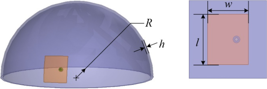
Figure 2: Antenna element structure.
According to the working frequency f of the antenna and the thickness h of the substrate, the width of the patch can be obtained by the following equation:
| (2) |
where c is the speed of light and is the dielectric constant of the substrate. Considering the edge shortening effect, the length of the patch can be obtained from the following equation:
| (3) |
where is the effective dielectric constant and is the extension length:
| (4) |
| (5) |
According to the above formula, the basic parameters of the patch can be obtained. After the patch is conformal to the curved surface carrier, the final size is obtained after adjustment: h = 0.254 mm, w = 2.675 mm, l = 3.24 mm.
B. Array designing and simulation
There are many arrangement methods of hemispherical antenna arrays, such as concentric circle projection method, rectangular projection method, and regular icosahedral spherical division method. The antenna array obtained by the projection method is sparsely distributed in the elevation direction, resulting in a serious waste of space. And the design of the regular icosahedral spherical division method is complicated. Therefore, this paper considers the method of equal spacing distribution, in which the spacing is at least half the wavelength. The arrangement of array elements is shown in Figure 3. The distance between adjacent elements is same whether in azimuth direction or elevation direction.
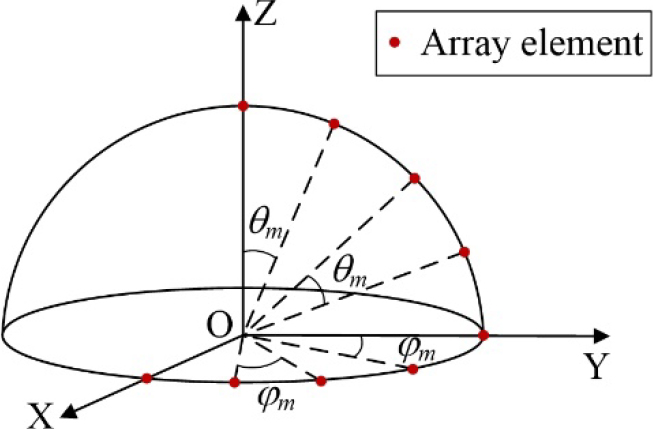
Figure 3: The arrangement of array elements.
Application programming interface (API) script is written in MATLAB and HFSS is called to complete automatic modeling. In this process, in order to achieve complete conformal array, the projection function is written to project the rectangular patch onto the substrate. In addition, the rotary and duplicate operation is used to complete the establishment of the whole model, so as to improve the modeling efficiency.
If the hemisphere is with a radius of , the final uniform antenna array is shown in Figure 4 after considering the influence of array elements mutual coupling. The array consists of layers of rings and elements in total. Each element uses coaxial feed alone. The distance between adjacent elements is .
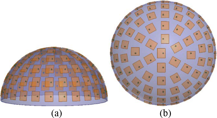
Figure 4: Hemispherical antenna array. (a) Main view. (b) Top view.
The beam scanning characteristics of the hemispherical antenna array are studied. It can be found that in the scanning process of elevation direction, the pattern begins to depress from , and the closer it is to , the more serious the depression is. By phase compensation of the elements, it can be found that the depression disappears and the maximum radiation direction of the pattern is consistent with the expectation. Therefore, the polarization problem of the array has been solved. Figure 5 shows the 2D pattern in elevation direction before and after phase compensation when the beam direction is . It can be seen from Figure 5 that the gain of the array has changed significantly, increasing from 15 to 17 dB. At the same time, it also verifies the correctness of the theory.
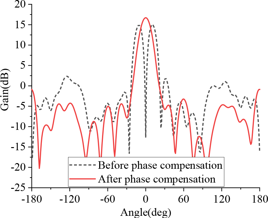
Figure 5: Comparison before and after phase compensation at .
After dealing with the polarization problem, the beam scanning performance of the array is analyzed again. Finally, the array can realize omni-directional scanning of in azimuth direction and wide-angle scanning of in the elevation direction. When the elevation direction is selected to be ,Figure 6(a) shows the 2D scanning pattern in azimuth direction. When the azimuth direction is selected to be , Figure 6 (b) shows the 2D scanning pattern in elevation direction.
It can be seen from Figure 6 that the gain of the hemispherical array is stable at about 17 dB during the beam scanning. With the increase of the scanning angle, the effective caliber of the hemispherical array remains unchanged, which is beneficial to the stable performance of the array during beam scanning. This gives the hemispherical array a very large scanning range.
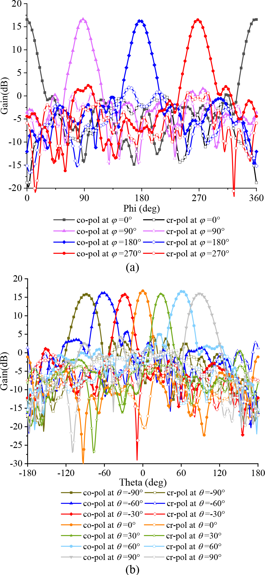
Figure 6: Beam scanning pattern of the hemispherical array. (a) Azimuth direction. (b) Elevation direction.
C. Thinned optimization of the array
In a planar array, the maximum effective radiation angle is generally 60. The performance of the array is compared when is taken as different values by referring to the situation of the planar array. Figure 7 shows the 2D pattern in elevation direction of different when is and .
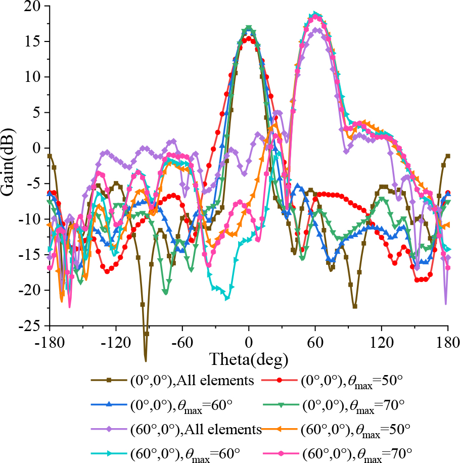
Figure 7: 2D pattern in elevation direction of different .
It can be concluded by comparison that when is different, the patterns at different scanning angles are also different. Generally, the pattern gain under three scanning angles is a little higher than that under full array, and the side lobe level is also slightly lower when . Figure 8 shows the thinned array under three scanning angles, in which the dark-colored selected part is the effective elements, while the light-colored unselected part is the invalid elements. The sparsity rates of the three are 55.4%, 48.2%, and 51.8%, respectively, all around 50%.
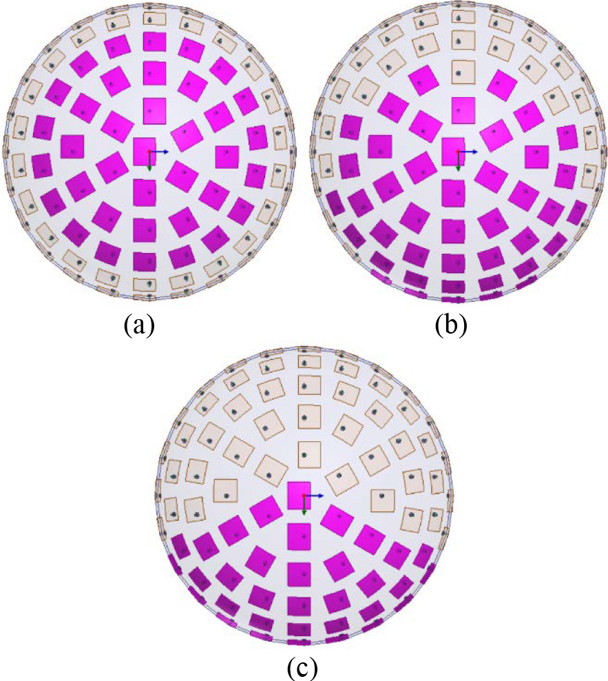
Figure 8: Thinned array at different scanning angles.
(a) . (b) .
(c) .
IV. CONCLUSION
In this paper, a hemispherical antenna array based on shape conformal is designed. The polarization problem during beam scanning of array is solved by the method of phase compensation, and omni-directional scanning in azimuth direction and wide-angle scanning in elevation direction are realized. The thinned array is used to achieve better scanning performance and reduce the power loss of the array.
ACKNOWLEDGMENT
This work was supported in part by the National Natural Science Foundation of China (61701278).
REFERENCES
[1] M. Liu, Z.-R. Feng, and Q. Wu, “A millimeter-wave cylindrical conformal phased microstrip antenna array,” 2008 China-Japan Joint Microwave Conference, pp. 150-153, 2008.
[2] T. K. Vo Dai, T. Nguyen, and O. Kilic, “A non-focal rotman lens design to support cylindrically conformal array antenna,” The Applied Computational Electromagnetics Society (ACES) Journal, vol. 33, no. 2, pp. 240-243, Feb. 2018.
[3] D. Gibbins, M. Klemm, I. Craddock, A. Preece, J. Leendertz, and R. Benjamin, “Design of a UWB wide-slot antenna and a hemispherical array for breast imaging,” 2009 3rd European Conference on Antennas and Propagation, pp. 2967-2970, 2009.
[4] H.-S. Lin, Y.-J. Cheng, Y.-F. Wu, and Y. Fan, “Height reduced concave sector-cut spherical conformal phased array antenna based on distributed aperture synthesis,” in IEEE Transactions on Antennas and Propagation, pp. 1-9, Apr. 2021.
[5] X.-J. Zhang, X.-P. Ma, and Q.-F. Lai, “Two kind of conical conformal GPS antenna arrays on projectile,” 2009 3rd IEEE International Symposium on Microwave, Antenna, Propagation and EMC Technologies for Wireless Communications, pp. 659-662, 2009.
[6] Z.-R. Li, L.-D. Tan, and X.-l. Kang. “A novel wideband end-fire conformal antenna array mounted on a dielectric cone,” The Applied Computational Electromagnetics Society (ACES) Journal, vol. 31, no. 8, pp. 933-942, Aug. 2016.
[7] Y. Li, J. Ouyang, F. Yang, and P. Yang, “Synthesis of conical conformal array antenna using invasive weed optimization method,” The Applied Computational Electromagnetics Society (ACES) Journal, vol. 28, no. 11, pp. 1025-1030, Nov. 2013.
[8] M. Arrebola, E. Carrasco, and J. A. Encinar, “Beam scanning antenna using a reflectarray as sub-reflector,” The Applied Computational Electromagnetics Society (ACES) Journal, vol. 26, no. 6, pp. 473-483, Jun. 2011.
[9] A. Mahmoodi and A. Pirhadi, “Enhancement of scan angle using a rotman lens feeding network for a conformal array antenna configuration,” The Applied Computational Electromagnetics Society (ACES) Journal, vol. 30, no. 9, pp. 959-966, Sep. 2015.
[10] Y.-B. Kim, S. Lim, and H. L. Lee, “Electrically conformal antenna array with planar multipole structure for 2-D wide angle beam steering,” in IEEE Access, vol. 8, pp. 157261-157269, Aug. 2020.
[11] W.-T. Li, X.-W. Shi, Y.-Q. Hei, S.-F. Liu, and J. Zhu, “A hybrid optimization algorithm and its application for conformal array pattern synthesis,” in IEEE Transactions on Antennas and Propagation, vol. 58, no. 10, pp. 3401-3406, Oct. 2010.
[12] X. Li, K. Gao, C. Li, C.-l. Li, and W. Chen, “Design of hemi-spherical conformal array with a wide-angle scanning,” 2016 IEEE International Conference on Microwave and Millimeter Wave Technology (ICMMT), pp. 461-463, 2016.
BIOGRAPHIES

Linqian Du was born in Jinan, Shandong Province, China, in 1996. She received the B.S. degree in engineering from Qufu Normal University, China, in 2019. In the same year, she was admitted to Qufu Normal University and became a graduate student.
Her research interest is the wide-angle scanning of conformal arrays.

Jianping Zhao was born in Heze, Shandong Province, China, in 1964. He received the B.S. degree in physics from Qufu Normal University, Qufu, China, in 1985. In 1988, he studied in Wuhan University for master’s degree in radio and information engineering.
Since 1985, he has worked with Qufu Normal University. He was promoted to Associate Professor in 1997 and Professor in 2002. Since 1992, he has been the Director of the Radio Teaching and Research Section. He has been engaged in application of electronic technology and scientific research in communication and information system of electronic information engineering and communication engineering.

Juan Xu was born in Jining, Shandong Province, China, in 1982. She received the Ph.D. degree in electronic science and technology from the Nanjing University of Science and Technology, Nanjing, China, in 2016.
Since 2016, she has been working with Qufu Normal University. She has been an Associate Professor since 2019. Her research interests include simulation, design, and experimental measurement of new high performance RF, microwave and millimeter wave passive devices, antennas, and antenna arrays.
ACES JOURNAL, Vol. 37, No. 4, 403–407.
doi: 10.13052/2022.ACES.J.370405
© 2021 River Publishers