Analysis of a Sinusoidal Rotor Segments Axial Flux Interior Permanent Magnet Synchronous Motor with 120-degree Phase Belt Toroidal Windings
Yansong Wang, Wenbing Zhang, Rui Nie, Jikai Si, Wenping Cao, and Yingsheng Li
Department of Electrical Engineering, Zhengzhou University, Zhengzhou 450001, China
wys1711@outlook.com, zwenbing@zzu.edu.cn*(corresponding author), ruinie1994@126.com, sijikai@zzu.edu.cn
Department of Electrical Engineering and Automation, Anhui University, Hefei 230601, China
19122@ahu.edu.cn
Zhengzhou Runhua Intelligent Equipment Co., Ltd., Zhengzhou 450004, China
xdlys@vip.sina.com
Submitted On: August 13, 2021; Accepted On: March 21, 2022
Abstract
Axial flux permanent magnet (AFPM) motors are widely applied in many applications due to their performance advantages. A novel AFPM which owns a special winding form (120-degree phase belt toroidal windings) and a distinct rotor structure (sinusoidal rotor segments) is proposed in this paper to further improve the torque density of this kind of machine. First, the structure and working principle of the 120-degree phase belt toroidal windings sinusoidal rotor segments AFPM interior synchronous motor (120D-TWSRSAFPMISM) are clarified. Then, the design formula and crucial parameters of the motor are presented. Subsequently, the cogging torque is optimized by dividing the magnet grouping. Finally, the characteristics of the 120D-TWSRSAFPMISM are analyzed and compared with those of the traditional toroidal windings sinusoidal rotor segments AFPMISM (T-TWSRSAFPMISM) and another T-TW motor without the sinusoidal rotor segments (T-TWAFPMISM) by finite element method (FEM). The results show that the 120D-TW can significantly increase the back electromotive force (EMF) compared with the T-TW, and the sinusoidal rotor segments can increase the air-gap flux density compared with the traditional interior rotor. Therefore, the 120D-TW and sinusoidal rotor segments are combined in the AFPM motor. This combination can further increase the torque density compared with the contrast motors.
Keywords: 120-degree phase belt toroidal windings, axial flux permanent magnet (AFPM) motor, magnet grouping, interior motor, sinusoidal rotor segments, torque density.
I. INTRODUCTION
Axial flux permanent magnet (AFPM) motors are commonly used in various applications, including traction, power generation, and so on due to their flexible structure. Compared with the traditional permanent magnet motors, they have some noticeable benefits, such as higher power/torque densities, torque-to-weight ratios, geometrically higher aspect ratios, and so on. They have several alternative topologies, such as cored or coreless (slotted or slotless) or coreless stators, overlap or nonoverlap concentrated windings, and single or multiple rotors/stator [1–12]. By changing these alternatives to AFPM motors to improve torque density, it has become a hot spot on many researchers.
In the last few years, some topologies of AFPM motors have been proposed. For example, in [12], an AFPM motor with single stator and single rotor is proposed. It has the advantages of compact structure and small cogging torque, but it has the disadvantages of low torque density and insufficient mechanical strength. To solve this problem, the motor structure of single stator and double rotor has attracted many researchers’ attention [13, 14]. In [13], a coreless AFPM motor with double rotors and single stator structure is proposed. Although it can effectively improve the torque density, its small air-gap flux, which needs to be improved to gain higher torque density. In [14], a new coreless axial flux interior permanent magnet synchronous motor with sinusoidal rotor segments is proposed. The sinusoidal rotor segmented structure is proposed to effectively improve the air-gap flux density of the interior motor by changing the rotor form, thus achieving the effect of improving the torque density. However, it has the disadvantages of high copper loss due to its overlap winding structure, and the coreless structure limits further improvement of the torque density. Many researchers proposed the methods to reduce copper loss by varying slot configuration, change winding structure and displacement of conductors [15–17]. Meanwhile, to further improve the torque density by changing the stator core structure and winding form is a convenient and effective method.
The stator core structure is classified into slotted type and slotless type. In order to further improve the torque density, the slotted structure is selected. For the slotted motor, the winding form can be mainly divided into tooth-wound windings and core-wound windings (toroidal windings). In [17], a single stator and double rotor AFPM motor with tooth-wound windings and core-wound windings are compared and analyzed. It is shown that toroidal windings can save more copper, reduce copper loss, and improve efficiency. In order to further develop the advantages of toroidal windings, in [18], 120-degree phase belt toroidal windings (120D-TW) is proposed to increase torque density by increasing the amplitude of the back-EMF. If the sinusoidal rotor segments and 120-degree phase belt toroidal windings structures are combined with single stator and double rotor AFPM motors, it may further improve the torque density. Therefore, a 120-degree phase belt toroidal windings sinusoidal rotor segments AFPM interior synchronous motor (120D-TWSRSAFPMISM) is proposed and analyzed in this paper.
The paper is structured as follows. Section II introduces the motor structure, winding configuration, and operating principle of the proposed motor, the traditional toroidal windings sinusoidal rotor segments AFPMISM (T-TWSRSAFPMISM), and T-TW motor without the sinusoidal rotor segments (T-TWAFPMISM), and analyzes its structural advantages. Section III introduces the design formula and structural parameters of the motor. Section IV introduces an optimization method of permanent magnet grouping to reduce the cogging torque of the proposed motor and establishes a parametric model to obtain better structure parameters. Section V introduces the results of the 3D finite element analysis (3D-FEA). Finally, some conclusions are summarized in Section VI.
II. MOTOR STRUCTURE AND OPERATING PRINCIPLE
A. Motor structure
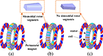
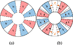
Figure 1 shows the structure of the proposed motors. Figure 1 (a) is the topology of the 120D-TWSRSAFPMISM. The proposed motor is an AFPM motor with single stator and double rotor. The stator is constructed with slotted and all windings are surrounded by toroidal on the stator yoke. The permanent magnet is inserted in two rotors with interior structure, which make the rotor like a wheel spoke. At the same time, the rotor is sinusoidal and divided by permanent magnet. Figures 1 (b) and (c) are proposed contrast motors: one is the T-TWSRSAFPMISM with sinusoidal rotor segment and other one is traditional toroidal windings interior permanent magnet axial flux permanent magnet synchronous motor (T-TWIPMAFPMSM) with no sinusoidal rotor segment.

Figure 1: Topology of the three motors. (a) 120D-TWSRSAFPMISM. (b) T-TWSRSAFPMISM. (c) T-TWAFPMISM.
B. Winding configuration
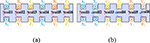
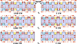
As shown in Figure 2, the winding configurations for the proposed motors are depicted. Figure 2 (a) is the winding configuration of the 120D-TWSRSAFPMSM. As can be seen from Figure 2 (a), the incoming line terminals (A, B, and C) of the 120D-TWSRSAFPMSM are all on the same side of the stator core and have the same winding direction. And its outcoming line terminals (X, Y, and Z) are all on the other side of the stator core. Figure 2 (b) is the winding configuration of contrast motors; its winding configuration is the traditional toroidal windings. And its positive side of coil and return side of coil are on either side of the stator.
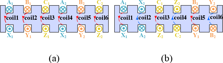
Figure 2: Winding configurations of the two types. (a) 120-degree phase belt toroidal windings. (b) Traditional toroidal windings.
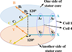
Figure 3 shows the vector diagram of synthetic electromotive force (EMF) of the 1/5 model of 120D-TWSRSAFPMSM. As can be seen, the synthetic EMF of phases A, B, and C are all on the one side of the stator core, and synthetic EMF of phases X, Y, and Z are all on the other side of the stator core due to the special layouts of the novel toroidal windings. It should be noted that there is no space vector misalignment of coil-EMF, which can improve the synthetic EMF. After the three-phase symmetrical current is fed into the novel toroidal windings, both sides of the stator core will generate a rotating magnet field with the identical direction. Then the two rotors will rotate synchronously under the interaction between the armature field and permanent magnets field.
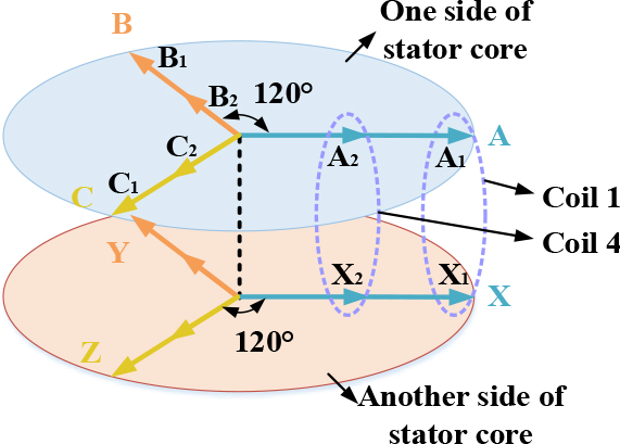
Figure 3: Vector diagram of A-phase synthetic EMF of the 1/5 model of 120D-TWSRSAFPMSM.
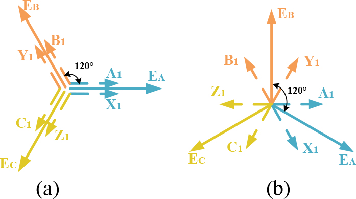
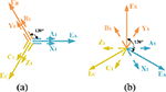
Figure 4: Vector of diagram of EMF. (a) 120D-TW.(b) T-TW.
At the same time, the winding factor of the three winding types needs to be analyzed, which further illustrates the advantages of 120D-TW. First, the formula of winding factor is given by
| (1) |
where K is pitch-shortening factor, K is distribution factor, and K is winding factor.
The K can be expressed as
| (2) |
where z is stator slot number, p is pole pairs, and m is phase number. From the above formula, the distribution factor is related to the number of coils in the unit motor. Both the motor and the comparison motor are concentrated windings; so it is known that the distribution factor K is 1.
The K can be calculated by
| (3) |
where N is the number of synthetic EMF for each phase EMF, and is the electrical degrees between the synthetic EMF. It can be seen from Figure 3 that the advantage of 120D-TW is that the angle between the coil and coil is 0; then EMF of phase A is derived from the formula
| (4) |
According to formula (3), the formula of pitch-shortening factor K of 120D-TW is given by
| (5) |
It shows that the pitch-shortening factor of 120D-TW of K is 1. For the same reason and it can be seen that the angle between the coil and coil is 120 electrical degrees, the A phase EMF of the traditional toroidal winding is derived from the formula
| (6) |
| (7) |
It shows that the pitch-shortening factor of traditional toroidal winding of K is 0.87. According to formula (1), the winding factors of 120D-TW and T-TW are 1 and 0.87, respectively. The winding factor of 120D-TW is 14.94% higher than that of T-TW, which means the 120D-TW has the ability to gain a higher back-EMF.
C. Operating principle
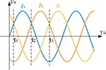
Figure 5 shows three moments of the three-phase current. Because the winding forms of the two contrast motors are the same (T-TW), only the armature magnetic field of one motor can be drawn. At the t, t, t moments, the armature magnetic field of the 120D-TW and the T-TW is shown in Figure 6.
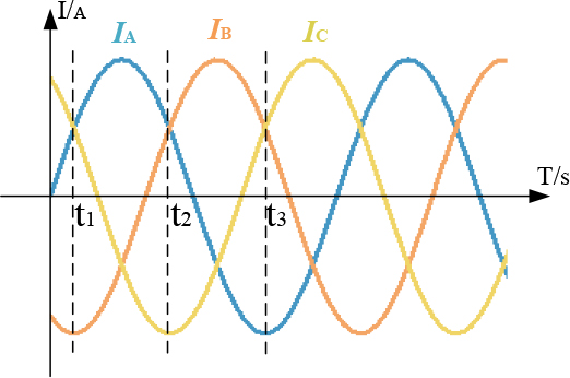
Figure 5: Three-phase current I I, and I.
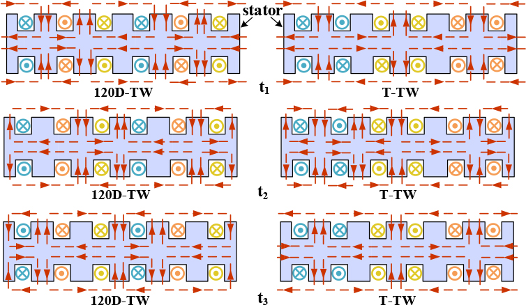
Figure 6: The t, t, and t moments of armature magnetic field.
Figure 7 shows the 1/5 model of the rotor structure of the proposed motor and the contrast motor, respectively. Figure 7 (a) is a sinusoidal rotor segments structure adopted by 120D-TWSRSAFPMSM and T-TWSRSAFPMSM, and Figure 7 (b) is an interior permanent magnet structure by T-TWIPMAFPMSM. It can be seen that the permanent magnets of the two rotors are embedded in the rotor and distributed along the axial direction, and the permanent magnets of the same axial direction have the same polarity. Two strands of flux wire driven by permanent magnets inside the two rotors through the air gap, winding, and stator core. It can be seen that the sinusoidal rotor segment is compared with the interior permanent magnet, and the magnetic lines of the former converge toward the sinusoidal type rotor, while the latter diverges. It is shown that the sinusoidal rotor segments have the function of converging magnetic lines; so it can increase the air-gap flux density.
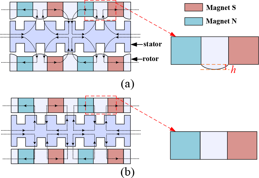
Figure 7: Flux distribution of two rotor types. (a) Sinusoidal rotor segments. (b) Interior permanent magnet.
III. DESIGN OF THE PROPOSED MOTOR
The main design equations of the proposed motor are presented in this section.
The AFPM diameter ratio is defined as
| (8) |
where D is the inner diameter, D is the outer diameter of the motor, is the ratio of D to D, P is the output power, A is the electrical loading, B is the air-gap flux density, and K is a constant incorporating winding factors. However, the winding form of 120D-TW is different from T-TW; the electrical load formula needs to be redefined. As shown in Figure 2, the windings of 120D-TW are winding in the same direction, similar to only out, and T-TW are winding in two directions, similar to in and out, resulting in the change in the number of series turns per phase; so the electric loading calculation formula should be changed accordingly.
The electric loading formula for the 120-degree phase belt toroidal windings is given by
| (9) |
The electrical load formula for the traditional toroidal windings is given by
| (10) |
where N is the number of series turns per phase, and I is current effective value. However, because the number of series turns per phase changes, the peak value of back-EMF formula also needs to change.The EMF for the 120-degree phase belt toroidal windings is given by
| (11) |
The EMF for the traditional toroidal windings is given by
| (12) |
The motor design is completed based on these fundamental sizing equations, and the initial motor design data are obtained. Then, contrast motors design is carried out by the same rotor D and the same amount of magnet volume. To verify the reasonability of the proposed motor, the 120D-TWSRSAFPMSM is compared with the contrast motors. The design of the three motors needs to follow some rules to ensure a fair comparison.
(1) The three motors have the same dimensions, including outer diameter and inner diameter of the stator and rotors, axial length, thickness of permanent magnet, and so on.
(2) The three motors are excited by a same current source and have the same materials.
Based on the principles above, the primary parameters of the 120D-TWSRSAFPMSM and contrast motors are presented in Table 1.
Table 1: Primary parameters of three motors
| Parameters | 120D-TWSRSAF PMSM |
T-TWSRSAF PMSM |
T-TWPMBAF PMSM |
|---|---|---|---|
| Rated speed | 800 r/min | 800 r/min | 800 r/min |
| No. of phase | 3 | 3 | 3 |
| No. of poles | 20 | 20 | 20 |
| No. of winding coils | 30 | 30 | 30 |
| Turns of per coil | 14 | 14 | 14 |
| Outer diameter of stator core | 148.0 mm | 148.0 mm | 148.0 mm |
| Inner diameter of stator core | 100.0 mm | 100.0 mm | 100.0 mm |
IV. OPTIMIZATION ANALYSIS
According to the primary parameters of the three motors presented in Table 1, first, the influence of sinusoidal rotor segments on the cogging torque is determined. Then, because all three motors are slotted, the cogging torque needs to be optimized. In this part, the magnet grouping division is used to reduce the cogging torque and establish a parametric model to obtain and analyze the results.
A. Sinusoidal rotor segments affect about cogging torque
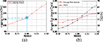
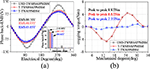
Because both 120D-TWSRSAFPMSM and T-TWSRSAFPMSM adopt the rotor structure of the sinusoidal rotor segments, we need to determine the parameter about h of the rotor segment, then the parametric model can be established, which is shown in Figure 7 (a). Because the sinusoidal rotor parameter h has a great impact on the cogging torque and torque density. The simulation results are shown in Figure 8. Figure 8 (a) shows that when h is in 1 mm, the cogging torque is at turning point. Figure 8 (b) illustrates the influence of h on the fundamental harmonic and total harmonic distortion (THD) of air-gap flux density. It can be seen that with the increase of h, the fundamental harmonic and THD of air-gap flux density also gradually increase. With the increase of the parameter h, the fundamental harmonic of air-gap flux density and the cogging torque will be definitely increased. Accordingly, h is selected as 1 mm for increasing the torque output and reducing the cogging torque as much as possible.
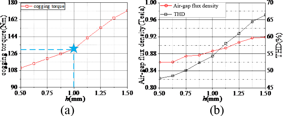
Figure 8: Effect of the parameter h change on the sinusoidal rotor segments. (a) Cogging torque. (b) Fundamental harmonic of air-gap flux density and THD.
B. Cogging torque optimization
Cogging torque is caused by interaction between magnets and stator slots. In other words, cogging torque is caused by the variation of the magnetic energy of the field due to the PM with the mechanical angular position of the rotor. Reducing cogging torque component is vital in PM motor design process especially at low speed and direct-drive applications.
In addition, the proposed motor inevitably has cogging torque due to the slotted structure [19]. The dissatisfactory torque ripple may be obtained due to the cogging torque. Therefore, the torque ripple needs to be optimized. In [20], an optimization method for magnet grouping is proposed to reduce the cogging torque. It shows that by moving the permanent magnet and grouping it, an asymmetric air-gap magnetic density is formed, which can greatly reduce the cogging torque. At the same time, the avoidance of the irregular permanent magnet shape reduces the manufacturing difficulty of the permanent magnet.
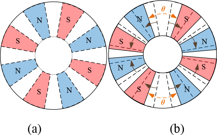
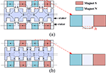
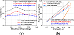
Figure 9: Division of the permanent magnets into two groups. (a) Before the group. (b) After the group.
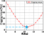
This technique is illustrated in Figure 9 for a grouping method for a multipolar motor. By moving the permanent magnet and grouping it, forming an asymmetric air-gap magnetic density can greatly reduce the cogging torque. At the same time, the avoidance of the irregular permanent magnet shape reduces the manufacturing difficulty of the permanent magnet. The parameterization model of the motor is shown in Figure 10. It can be seen that the grouping angle is 10.5, and the cogging torque ripple is 9.2%, which is the lowest in this data compared with other angles.
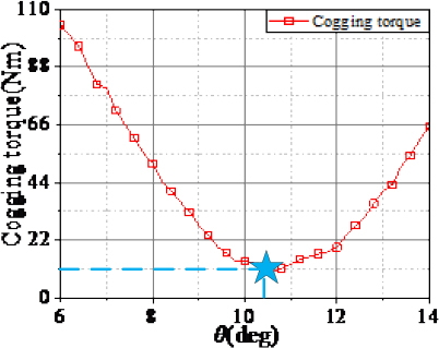
Figure 10: Effect of the parameter change on the cogging torque ripple.
V. CHARACTERISTICS ANALYSIS
According to the primary parameters of the three motors presented in Table 1 and the result of optimization analysis, the 3D model of the three motors are established by 3D FEA software (ANSYS Maxwell). Subsequently, the operating characteristics under no-load and load conditions are analyzed, respectively.
A. No-load characteristics
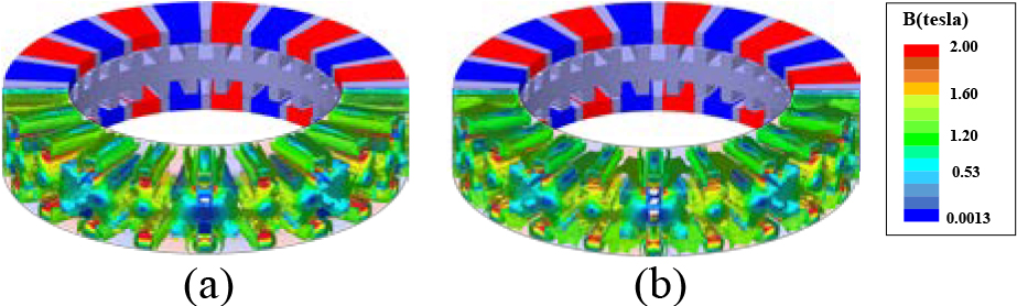
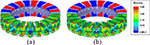
Figure 11: No-load flux graph of motor. (a) Sinusoidal rotor segments. (b) Interior permanent magnet.

Figure 12: Air-gap flux density and its harmonics distribution of the three motors under no-load condition. (a) Air-gap flux density. (b) Harmonics distribution.
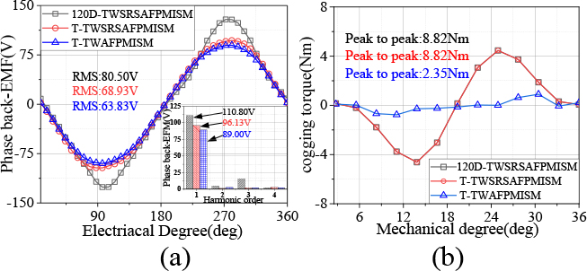
Figure 13: (a) Back-EMF waveforms and its harmonics distribution of the three motors under no-load condition. (b) Cogging torque of the three motors.
Table 2: No-load characteristics of three motors
| Parameters | 120D-TWSRSAF PMSM |
T-TWSRSAF PMSM |
T-TWPMBAF PMSM |
|---|---|---|---|
| RMS of the back-EMF | 80.50 V | 68.93 V | 63.83 V |
| Fundamental harmonic of the back-EMF | 110.80 V | 96.13 V | 89.00 V |
| Total harmonic distribution (THD) | 12.04% | 5.09% | 5.33% |
| Peak-to-peak value | 8.82 Nm | 8.82 Nm | 2.35 Nm |
| No-load flux graph of the stator core | 1.40 T | 1.40 T | 1.40 T |
Figure 11 shows the no-load flux graph of the two structures. It can be seen that the stator of two structures both have higher flux density in their teeth. However, the flux density of the stator core of the two structures is 1.41 T, and no magnetic saturation occurs in the stator core. The air-gap flux density and its harmonics distribution of the three motors under no-load condition are presented in Figure 12. It can be seen from Figure 12 (a) that the air-gap flux density curve in the 120D-TWSRSAFPMISM is basically the same as that in the T-TWSRSAFPMISM, which is higher than T-TWAFPMISM. As shown in Figure 12 (b), the amplitudes of the fundamental harmonic of the air-gap flux density in the 120D-TWSRSAFPMISM and T-TWSRSAFPMISM are both 0.85 T, and the T-TWAFPMISM is 0.76 T. It can be seen that the first two increased by 11.84% compared with the latter, which can be seen that sinusoidal rotor segments can effectively increase flux density.
The no-load back-EMF, harmonics distribution, and cogging torque of the three motors are presented in Figures 13 (a) and (b), respectively. Comparative analysis results of the three motors are shown in Table 2. As shown in Table 2, it can be seen that the amplitudes of the fundamental harmonic of the back-EMF of the 120D-TWSRSAFPMISM are increased by 15.26% and 24.49% compared with the T-TWSRSAFPMISM andT-TWAFPMISM. In formula (8), it can be seen that the back-EMF is related to the winding coefficient K and the air-gap flux density B. Because the sinusoidal rotor segments can effectively improve the air-gap flux density, and combined with the advantages of high winding coefficient of 120D-TW, the fundamental harmonic of the back-EMF of 120D-TWSRSAFPMISM is greatly increased. And it is consistent with the analysis of the vector diagram of A-phase synthetic EMF of the three motors.
As shown in Table 2, the cogging torque of 120D-TWSRSAFPMISM and T-TWSRSAFPMISM are nearly the same, and the peak-to-peak values of both are 8.82 Nm. The cogging torque of T-TWAFPMISM is the smallest, and its peak-to-peak value is only 2.35 Nm. Compared with T-TWAFPMISM, the cogging torques of 120D-TWSRSAFPMISM and T-TWSRSAFPMISM both increased. Because the sinusoidal rotor segments structure increases the air-gap flux density, which also affects the cogging torque.
B. On-load characteristics
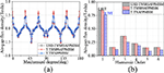
The torque curve and torque-current characteristic of the three motors are presented in Figures 14 (a) and (b), respectively. Comparative analysis results of the three motors are shown in Table 3.
Table 3: On-load characteristics of three motors
| Parameters | 120D-TWSRSAF PMSM |
T-TWSRSAF PMSM |
T-TWPMBAF PMSM |
|---|---|---|---|
| Average torque | 113.67 Nm | 98.38 Nm | 91.67 Nm |
| Torque per ampere | 2.84 Nm/A | 2.46 Nm/A | 2.29 Nm/A |
| Average torque density | 25.43 kNm/m | 22.01 kNm/m | 20.51 kNm/m |
| Torque ripple | 14.71% | 17.10% | 7.33% |
| Output power | 9.52 kW | 8.24 kW | 7.68 kW |
As shown in Table 3, compared with the T-TWSRSAFPMISM and T-TWAFPMISM, the torque density of the 120D-TWSRSAFPMISM has increased by 15.54% and 24.0%, which can be seen that combining 120D-TW with sinusoidal rotor segments in the proposed motor can further improve torque density. And in Figure 14 (b), it shows the torque-current characteristic of three motors. As can be seen, within the whole current range, the 120D-TWSRSAFPMISM always has much higher average torque than the T-TWSRSAFPMISM and T-TWAFPMISM.
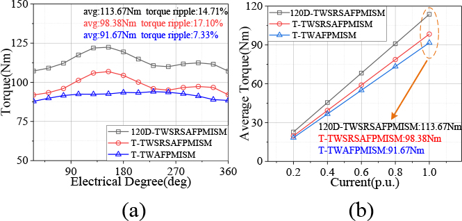
Figure 14: (a) Torque curve of three motors at the same current. (b) Torque-current characteristic of three motors.
VI. CONCLUSION
In this paper, a 120D-TWSRSAFPMISM is proposed and presented. The structure and working principle of the proposed motor are defined. The cogging torque of the motor is reduced by dividing the permanent magnets into two groups and the 3D finite element model of 120D-TWSRSAFPMISM and contrast motors are established. The no-load and load characteristics of the 120D-TWSRSAFPMISM are compared with contrast motors, which are designed with the same effective size.
In 120D-TWSRSAFPMISM, 120D-TW is combined with sinusoidal rotor segments. The difference between 120D-TW and T-TW lies in that the coil-EMF of 120D-TW has no space vector misalignment; so 120D-TW makes the amplitude of back-EMF increase by 14.94% compared with T-TW. The difference between sinusoidal rotor segments and traditional interior rotor is that the structure of sinusoidal rotor segments is sinusoidal, so that the flux field converges to the same place, making the air-gap flux density of structure sinusoidal rotor segments increase by 11.84% compared with the structure of traditional interior rotors. The simulation results show that the torque density of 120D-TWSRSAFPMISM increases by 15.54% and 24% compared with T-TWSRSAFPMISM and T-TWAFPMISM. Thus, the combination of the two structures in the proposed motor makes the torque density of the motor further improve compared with that of one structure.
ACKNOWLEDGMENT
This work is partially supported by Natural Science Foundation of China under Grant 51777060 and the China Postdoctoral Science Foundation under Grant 2020M682342, and in part by the Major Special Project for Collaborative Innovation in Zhengzhou under Grant 20XTZX12023.
REFERENCES
[1] F. Zhao, T. A. Lipo, and B. Kwon, “A novel dual-stator axial-flux spoke-type permanent magnet vernier machine for direct-drive applications,” IEEE Transactions on Magnetics, vol. 50, no. 11, pp. Art ID. 8104304, Nov. 2014.
[2] V. Rallabandi, N. Taran, D. M. Ionel, and J. F. Eastham, “Coreless multidisc axial flux pm machine with carbon nanotube windings,” IEEE Transactions on Magnetics, vol. 53, no. 6, pp. Art ID. 8102904, Jun. 2017.
[3] X. Luo, S. Niu, and W. N. Fu, “Design and sensorless control of a novel axial-flux permanent magnet machine for in-wheel applications,” IEEE Transactions on Applied Superconductivity, vol. 26, no. 7, pp. Art ID. 0608105, Oct. 2016.
[4] T. Rodrigo, D. S. Daniel, R. Oscar, and P. Rodrigo, “Dynamic modeling and parametric analysis of the magnetic stiffness on a radial heteropolar rotor magnetic bearing (RMB),” Journal of Electrical and Computer Engineering Research, vol. 1, no. 1, pp. 9-14, Jun. 2021.
[5] B. Rezaeealam and F. Rezaeealam, “Optimization of permanent magnet synchronous motors using conformal mappings,” Applied Computational Electromagnetic Society (ACES) Journal, vol. 32, no. 10, pp. 915-923, Oct. 2017.
[6] G. D. Liu, Y. Z. Wang, X. P. Xu, W. Y. Ming, and X. Zhang,“The optimal design of real time control precision of planar motor,” Applied Computational Electromagnetic Society (ACES) Journal, vol. 32, no. 10, pp. 948-954, Oct. 2017.
[7] J. L. Zhao, X. W. Quan, X. D. Sun, J. Li, and M. Y. Lin, “Design of a novel axial flux rotor consequent-pole permanent magnet machine,” IEEE Transactions on Applied Superconductivity, vol. 30, no. 4, pp. Art ID. 5205506, Jun. 2020.
[8] J. Wang, X. Yuan, and K. Atallah, “Design optimization of a surface-mounted permanent-magnet motor with concentrated windings for electric vehicle applications,” IEEE Transactions on Vehicular Technology, vol. 62, no. 3, pp. 1053-1064, Mar. 2013.
[9] H. Li, Z. Q. Zhu, and H. Hua, “Comparative analysis of flux reversal permanent magnet machines with toroidal and concentrated windings,” IEEE Transactions on Industrial Electronics, vol. 67, no. 7, pp. 5278-5290, Jul. 2020.
[10] N. Taran, G. Heins, and D. M. Ionel, “Coreless and conventional axial flux permanent magnet motors for solar cars,” IEEE Transactions on Industry Applications, vol. 54, no. 6, pp. 5907-5917, May 2018.
[11] B. Zhang, T. Seidler, R. Dierken, and M. Doppelbauer, “Development of a yokeless and segmented armature axial flux machine,” IEEE Transactions on Industrial Electronics, vol. 63, no. 4, pp. 2062-2071, Apr. 2016.
[12] J. H. Choi, J. H. Kim, D. H. Kim, and Y. S. Bake, “Design and parametric analysis of axial flux PM motors with minimized cogging torque,” IEEE Transactions on Magnetics, vol. 45, no. 6, pp. 2855-2858, Jun. 2009.
[13] Y. Zhang, N. Liu, S. Guo, J. Tong, and Q. Zhou, “Analysis and design of ironless axial flux permanent magnet synchronous motor,” IEEE 2018 10th International Conference on Intelligent Human-Machine Systems and Cybernetics., Hangzhou, China, pp. 170-173, Aug. 2018.
[14] M. Aydin and M. Gulec, “A new coreless axial flux interior permanent magnet synchronous motor with sinusoidal rotor segments,” IEEE Transactions on Magnetics, vol. 52, no. 7, pp. Art ID. 8105204, Jul. 2016.
[15] M. Popescu and D. G. Dorrell, “Skin effect and proximity losses in high speed brushless permanent magnet motors,” IEEE Energy Conversion Congress and Exposition, Denver, CO, USA, pp. 3520-3527, Sep. 2013.
[16] A. S. Thomas, Z. Q. Zhu, and G. W. Jewell, “Proximity loss study in high speed flux-switching permanent magnet machine,” IEEE Transactions on Magnetics, vol. 45, no. 10, pp. 4748-4751, Oct. 2009.
[17] G. D. Donato, F. G. Capponi, and F. Caricchi, “Fractional-slot concentrated-winding axial-flux permanent-magnet machine with core-wound coils,” IEEE Transactions on Industry Applications, vol. 48, no. 2, pp. 630-641, Apr. 2012.
[18] C. X. Gao, M. Z. Gao, J. K. Si, Y. H. Hu, and C. Gan, “A novel direct-drive permanent magnet synchronous motor with toroidal windings,” Energies, vol. 12, no. 3, pp. Art ID. 432, Feb. 2019.
[19] W. Cheng, G. Gao, Z. Deng, L. Xiao, and M. Li, “Torque comparison between slotless and slotted ultra-high speed AFPM motors using analytical method,” IEEE Transactions on Magnetics, vol. 58, no. 2, pp. Art ID. 8101805, May 2021.
[20] M. Gulec and M. Aydin, “Influence of magnet grouping in reduction of cogging torque for a slotted double-rotor axial-flux PM motor,” IEEE International Symposium on Power Electronics Power Electronics, Electrical Drives, Automation and Motion, Sorrento, Italy, pp. 812-817,Aug. 2012.
BIOGRAPHIES

Yansong Wang received the B.S. degree in automation from the Harbin University of Science and Technology in 2019. He is currently working toward the M.S. degree with the School of Electrical Engineering of Zhengzhou University, Zhengzhou, Henan.
His research interests include design, analysis, and control of axial-flux permanent magnet motors.

Wenbing Zhang (Non-member) majored in computer application from Nanjing Power Higher Specialized School, Nanjing, China, in 1994, and received the B.S. degree in computer science and technology from Zhengzhou University, Zhengzhou, China, in 2000.
His main research interests include numerical simulation and computation.

Rui Nie received the B.S. degree in electrical engineering from Henan Polytechnic University, Jiaozuo, China, in 2015, and the Ph.D. degree in electrical engineering from the China University of Mining and Technology, Xuzhou, China, in 2020. She is currently doing post-doctoral research at Zhenzhou University.
Her current research interests include linear motor design and control and renewable energy generation technology.

Jikai Si (Member, IEEE) received the Ph.D. degree in 2008 from the School of Information and Electrical Engineering, China University of Mining and Technology, Xuzhou, China, in 2008.
He is currently a Distinguished Professor with Zhengzhou University. His main research interests include the theory, application, and control of special motor. He has authored and co-authored over 160 technical papers in these areas. Prof. Si is a Member of the Green Motor System Professional Committee, China.

Wenping Cao (Senior Member, IEEE) received the B.Eng. degree in electrical engineering from Beijing Jiaotong University, Beijing, China, in 1991, and the Ph.D. degree in electrical machines and drives from the University of Nottingham, Nottingham, U.K., in 2004.
He was a Chair Professor of electrical power engineering and the Head of the Power Electronics, Machines, and Power System Group, Aston University, Birmingham, U.K. He is currently a Distinguished Professor with Anhui University, Hefei, China.

Yingsheng Li currently works in Zhengzhou Runhua Intelligent Equipment Co., Ltd, and is the legal representative of Zhengzhou Runhua Intelligent Equipment Co., Ltd. His research interests include the application, control of motor, and power electronics converters and control, and electrical motor drives.
ACES JOURNAL, Vol. 37, No. 4, 507–515.
doi: 10.13052/2022.ACES.J.370416
© 2021 River Publishers