A Novel Double-layer Low-profile Multiband Frequency Selective Surface for 4G Mobile Communication System
Şakir Balta and Mesut Kartal
Department of Electronics and Communication Engineering, Faculty of Electrical and Electronics, Istanbul Technical University, Istanbul, Turkey
sakirbalta@itu.edu.tr
Department of Electronics and Communication Engineering, Faculty of Electrical and Electronics, Istanbul Technical University, Istanbul, Turkey
kartalme@itu.edu.tr
Submitted On: August 18, 2021; Accepted On: April 4, 2022
Abstract
A novel double-layer multiband, low-profile frequency selective surface (FSS) for IMT-Advanced (4G) mobile communication system is presented in this article. On aspired to a minimum transmission coefficient of 10 dB for surface materials when the frequency bands targeted for blocking are stopped. For this project, we chose the dielectric substrate FR4 (loss-tangent = 0.02; dielectric constant = 4.54) and a thickness of 1 mm. Dodecagonal rings, upright bars, and square frame make up the FSS unit cell. The desired frequency responses of the FSS were intended to avoid being changed according to the angle of incidence of the electromagnetic waves. The FSS design is proposed as a symmetrical structure to make it polarization-independent and is aimed to stop 800, 900, 1800, 2100, and 2600 MHz frequencies to prevent harmful effects to human health and interference effects at these frequencies. With a cell size of 0.17, the planned FSS is quite small and, thus, has a low sensitivity at the angle of the incident wave. In addition, FSS geometry was manufactured by a printed circuit board (PCB) and measured in a non-reflective environment after being studied in Ansys high-frequency structure simulator (HFSS) software. By comparing the analysis and measurement results of the design, the success of the FSS to the frequencies to be stopped has been verified. The effect of each patch on different frequencies has been examined by drawing the surface current density graphs of the design.
Keywords: Ansys HFSS, frequency selective surface (FSS), FR4, GSM, 4G IMT-Advanced, PCB.
I. INTRODUCTION
Communication systems are constantly diversifying to meet our needs and finding solutions to our problems with the use of different frequencies. The IMT-Advanced 4G GSM mobile communication system, which iscurrently widely used in mobile communication, also provides high-speed communication by using frequency bands of 800, 900, 1800, 2100, and 2600 MHz. The widespread usage of these new frequency bands gives rise to information security and interference problems between neighboring wireless networks. In addition, the use of each different frequency is a threat to human health. Advanced signal processing techniques and antenna designs attempt to solve these problems. At any time in a daily struggle whereas at home or at the office, exposure to these frequencies is inevitable by reason of not having a prevention system [1]. On the other hand, penetration of a radio frequency (RF) signal to inside of a building can result in interference problems and reduction on communication speed and quality [2].
An important approach to solving all these problems is to isolate the frequency bands used by wireless networks from each other [3]. Periodic arrays of conductive patches or apertures placed on a dielectric medium exhibit reflection and transmission properties that vary with frequency [4]. Antenna and microwave fields have so many applications such as multiband microwave antennas, artificial magnetic conductors, polarizers, radomes, beam splitters, absorber surface designs, etc. Frequency-selective surfaces at various wireless communication systems have begun to be investigated because of finding solutions to problems such as interference, security, signal strength weakening [5], etc. Latest researches on FSS focus on areas with the substrate-integrated waveguide [6], miniaturized frequency selective surfaces (MEFSS) [7], multiband [8], and active [9].
FSS expands a wide range of resonance frequencies. Therefore, many other currently using frequencies are included unintentionally. This leads to importance of minimizing the interference of incoming radio frequency waves, which needs to be prevented on these convergent frequency bands. Hence, designing a structural surface material at other frequencies with decent transmission characteristics is crucial [10, 11]. On the other side, there is not enough research on multi-resonant FSS structures that prevent frequency bands of 800, 900, 1800, 2100, and 2600 MHz. In this work, a design is proposed with the goal of achieving a transmission coefficient () of the material in the extinguishing band of at least 10 dB. This design also targets a transmission coefficient () of the transmission band that is near to 0 dB. Another goal for this design is to be very compact, and low sensitivity to incoming wave angle is also a key characteristic.
Two different types of surface waves occur in FSSs. The first type of surface wave, in the condition that the distance between periodic geometries is greater than half of the resonance wavelength, undesired emissions occur in the dielectric layer, called surface waves [12]. The surface waves tend to propagate at frequencies where undesired radiation occurs when they come to the dielectric surface at an angle less than the critical angle and they cause radiation. The second type of surface waves occurs at frequencies that contain a limited number of periodic elements and where the distance between periodic elements is less than half of the resonance wavelength, 20%-30% lower than the resonance frequency [13]. FSS geometries should be placed quite frequently and periodically in order to prevent scattering in the surface waves and to increase the performance at the targeted frequencies.
Generally, wave equation solutions for FSS geometries are done by methods with numerical solutions, whereas solving basic FSS geometries are possible by using Floquet’s theory and periodic boundary conditions analytically [10]. Computer technology is developing swiftly. Therefore, applications for numerical analysis methods are now available in this area. Finite-difference time-domain (FDTD) method [14], finite element method (FEM) [15], and method of moments (MoM) are used [16] for obtaining numerical solution methods in FSS geometry analyses.
The design phase is the crucial part for determining the analysis of the FSSs which is finalized with “finite element method” throughout the numerical analysis procedure. Moreover, calculation of transmission and reflection coefficients is done in the preferred frequency range. Such structures with the “FEM” [15] can be analyzed by using Ansys high-frequency structure simulator (HFSS) program.
If we compare our work with similar studies in the literature, the innovations we have brought to the literature are clearly seen. As seen in previous designs, FSS cells are generally designed to block a single frequency [17, 18]. However, in this study, we applied a unique design that blocks these five different frequency bands for the first time in the literature. When we look at the graph plotted in the sample article [19], based on the response of the design only to relatively distant frequencies such as 2.4 and 5.8 GHz, it is seen that FSS has a much wider band than ours and affects other frequency regions as well. Our study gives much narrower band responses to the five different frequencies, without affecting frequencies outside of the operating frequencies. If the simulation results and measurement results are compared, it is seen that, unlike other studies [20], simulation results and measurement results are extremely similar and there is no frequency shift in our study.
II. DESIGN OF THE FSS
A. The decision of the structure
The desired frequency responses of the FSS to be designed have been wanted not to be changed depending on the angle of incidence of electromagnetic wave. IMT-Advanced 4G GSM frequencies are 800, 900, 1800, 2100, and 2600 MHz [21]. Because the 4G frequency bands are in close proximity to one another, it has been particularly challenging to design without affecting transmission characteristics at the transmission bands as much as possible, which is why the FSS is designed to be multi-resonant. In this study, simple FSS geometries are curved, whose periods are much smaller relative to the wavelength, and miniature FSS geometries were obtained; thus, the stability of the surfaces has been increased. The sensitivity of this relatively tiny design to the incident wave angle is quite low. The period of the geometry was obtained as 0.17 times the smallest resonance wavelength ( at 800 MHz). Thus, the stability of the FSS for different angles of incidence of the electromagnetic wave is increased and unwanted emission is provided at much higher frequencies [6]. It has been observed that the obtained FSS exhibits a stable frequency characteristic behavior to the electromagnetic wave which is up to an angle of incidence of 60 to surface normal. For the FSS that has more than one stop band, the resonant geometries of the FSS are placed into the unit cell as hybrid or nested or in different layers.
The interference between resonant geometries is particularly the most important problem encountered at this stage. In this study, new design techniques have been introduced for the solution of the issue. As suggested from the knowledge from the first technique, the interference effect decreases proportionally with the square of the distance. To control the distance between resonant geometries, nested geometries were used in the design. The interference effect can be avoided by keeping the interior geometry distance between interlocking geometries with a high degree of miniaturization as large as possible. Patch-type FSS is selected because it provides a stop band response, which is in line with the design’s goal.
A double-layer FSS unit cell is shown in Figure 1. Square patches are used on the top layer to prevent the 800 MHz frequency, “L” bars are integrated on the bottom layer to be effective at 900 and 1800 MHz frequencies, cross is integrated to stop the 2100 MHz frequency, and dodecagons are used to support the stopping characteristics at 2600 MHz and other frequencies in this FSS unit cell.
B. Dimension of the proposed structure
Electrical properties and thicknesses of dielectric substrates change the frequency characteristics of FSSs. For the dielectric layers to have a minimum effect on the frequency response of the FSS, these layers’ electrical properties must be stable and their dependence on ambient temperature is not desired to be high. The costs and difficulties in obtaining these substrates are other important issues to consider. All of this information led to the selection of FR4 as the dielectric material in the design. A 1-mm dielectric with a dielectric constant of 4.54 and a loss tangent of 0.02 has been developed. Different FSS/dielectric arrangements will influence the frequency selective response to a different extent and improve the stability of FSS performance over a range of incident angles. In order to make the FSS less sensitive to different angles of incidence, the dielectric layer thickness, the dielectric constant, and the loss tangent values were selected at their optimal levels.
There are two layers in the proposed FSS: a top layer and a bottom layer. Figure 1 and Tables 1 and 2 show the dimensions of the patch elements.
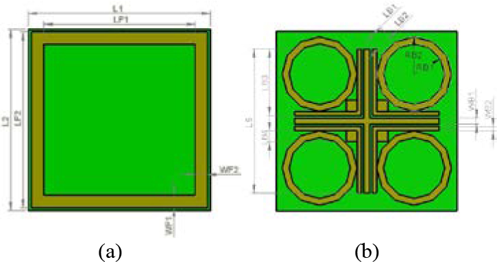
Figure 1: FSS unit dimensions: (a) the top layer of FSS with dimensions; (b) the bottom layer of FSS with dimensions.
Table 1: Dimensions of the top layer’s structures
| Dimensional names | Symbol | Value in |
| (mm) | ||
| A single substrate length | L1 | 65 |
| Other substrate lengths | L2 | 65 |
| Small square’s length | LF1 | 52 |
| Length of big square | LF2 | 63 |
| Big square’s length | WF1 | 5.5 |
| Width of lower edge | WF2 | 5.5 |
Table 2: Dimensions of the bottom layer’s structures
| Dimensional names | Symbol | Value in |
| (mm) | ||
| Outer dodecagon radius | RB2 | 13.46 |
| Inner dodecagon radius | RB1 | 11 |
| Outer dodecagon length | LB1 | 6.98 |
| Inner dodecagon length | LB2 | 5.70 |
| Outer rectangle length | LB3 | 24 |
| Small square length | LB4 | 4 |
| Cross length | LB5 | 52 |
| Cross width | WB1 | 2.2 |
| Outer rectangle width | WB2 | 1.5 |
III. RESULTS AND DISCUSSION
The simulation results in this study were repeated in the ANSYS Electronic Desktop 2020 R2 program for 631 points between 0.5 and 3 GHz. Here, it is aimed to make a one-to-one comparison with the measurement results. HFSS simulates an infinitely periodic unit cell using the Floquet ports and periodic boundaries defined in the software, by making use of the real-life adaptation of Floquet’s theorem. Once a Floquet port is defined, a set of modes known as Floquet modes represent areas on the port boundary. Floquet modes are plane waves with a propagation direction determined by the phase, frequency, and geometry of the periodic structure. The design presented a multiband behavior. At each desired frequency band, simulations are run for both TE and TM polarizations, while the incident wave’s angle ranges from 0 to 60. Because the frequency bands of 800 and 900 MHz are adjacent, these two frequency bands were both suppressed by the same structure. Attenuation of at least 10 dB for wide oblique incidence angles was achieved in all frequency bands using multilayer geometries.
On the basis of simulation results for different incidence angles and each desired frequency band, the parameters of the proposed FSS in TE polarization are shown in Figure 2.
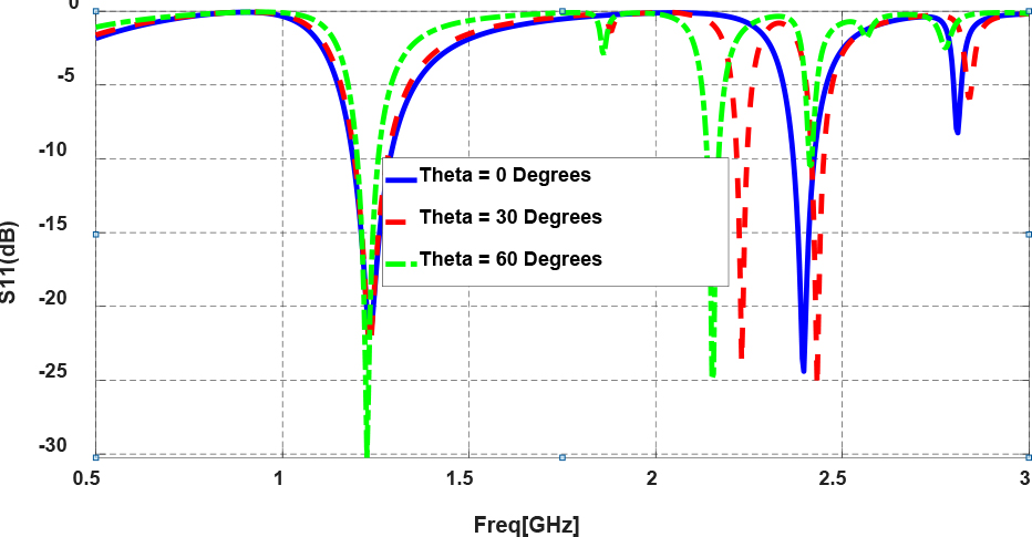
Figure 2: Simulated reflection coefficient () for TE polarization at various incidence angles.
Based on simulation findings at different incidence angles and in each required frequency band, parameters of the proposed FSS in TE polarization are shown in Figure 3 and Table 3.
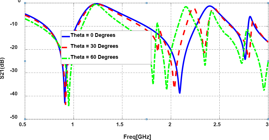
Figure 3: Simulated transmission coefficient () for TE polarization at various incidence angles.
Table 3: Transmission coefficient at different frequencies and incidence angles for TE polarization
| Frequencies (MHz) | |||||
|---|---|---|---|---|---|
| Angle (degrees) |
800 MHz | 900 MHz | 1800 MHz | 2100 MHz | 2600 MHz |
| 0 | 15 | 41 | 13 | 38 | 11 |
| 30 | 15 | 44 | 14 | 18 | 11 |
| 60 | 16 | 26 | 32 | 10 | 14 |
Based on simulation results at varied incidence angles and each target frequency band, parameters of the proposed FSS in TM polarization have been illustrated in Figure 4. parameters of the proposed FSS in TM polarization are shown in Figure 5 and Table 4 based on the simulation results at different incidence angles and in each desired frequency band. When the simulation results for both incidence wave angles varies from 0 to 60, whereas the FSS has a consistent frequency behavior, with attenuation of up to 44 dB in the IMT-Advanced frequency bands.
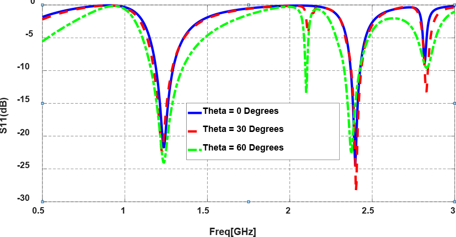
Figure 4: Simulated reflection coefficient () at different incidence angles for TM polarization.

Figure 5: Simulated transmission coefficient () at different incidence angles for TM polarization.
Table 4: Transmission coefficient at different frequencies and incidence angles for TM polarization
| Frequencies (MHz) | |||||
|---|---|---|---|---|---|
| Angle (degrees) | 800 MHz | 900 MHz | 1800 MHz | 2100 MHz | 2600 MHz |
| 0 | 15 | 43 | 13 | 39 | 10 |
| 30 | 15 | 44 | 12 | 15 | 11 |
| 60 | 8 | 20 | 9 | 10 | 10 |
After simulations, the FSS was fabricated by using 65 mm 65 mm FR4 dielectric, with a thickness of 1 mm, a relative dielectric constant of 4.54, and a loss tangent of 0.02. The top layer and the bottom layer of the produced FSS are shown in Figures 6 and 7. After the FSS was produced, the measurement setup is shown in Figure 8, and Figure 9 was prepared in order to make measurements. The Vivaldi antenna capable of radiating in the frequency ranges of 600 MHz and 3 GHz was positioned as a transmitter at a distance of about 1.5 m from the FSS surface, and an identical Vivaldi antenna at the same distance on the receiver side and the measurement results of the E8362C model belonging to Agilent Technologies company, shown in Figure 8, were collected with a Network Analyzer that can operate in the frequency range of 10 MHz to 20 GHz.
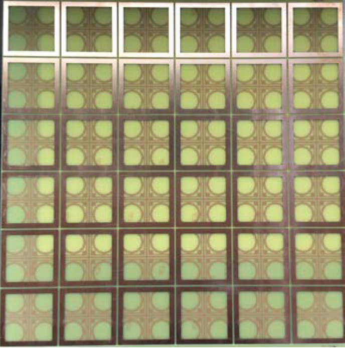
Figure 6: Top layer of the fabricated FSS.
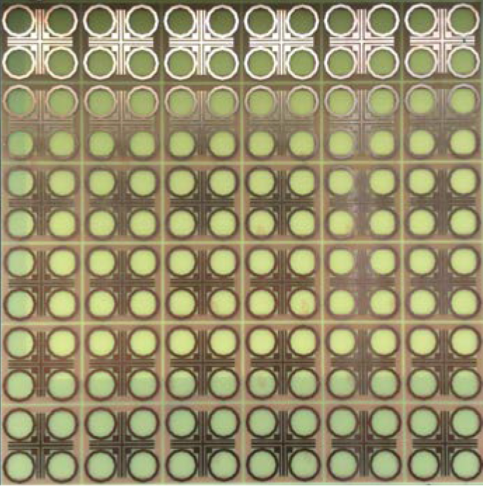
Figure 7: Bottom layer of the fabricated FSS.
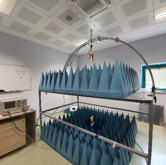
Figure 8: The measurement room and measurement setup.
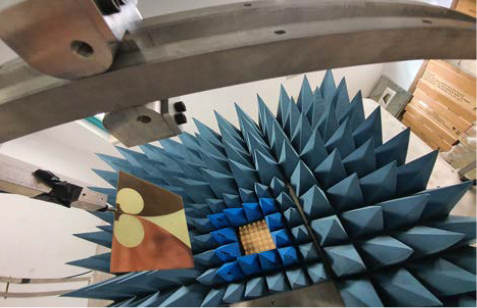
Figure 9: The measurement setup.

Figure 10: Measured transmission coefficient ( ) at different incidence angles for TE polarization.
On the basis of the measurement results at different incidence angles and in each desired frequency band, the parameters of the proposed FSS in TE polarization are shown in Figure 10. Measurement and simulation results for different incidence angles at each desired band are also presented in Figure 11. Figure 12 shows the parameters of the proposed FSS in TM polarization. For each desired band, Figure 13 shows the comparison of the measurement and simulation results in TM polarization for different incidence angles.
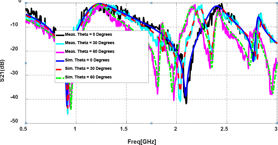
Figure 11: Measured and simulated transmission coefficient ( ) at different incidence angles for TE polarization.
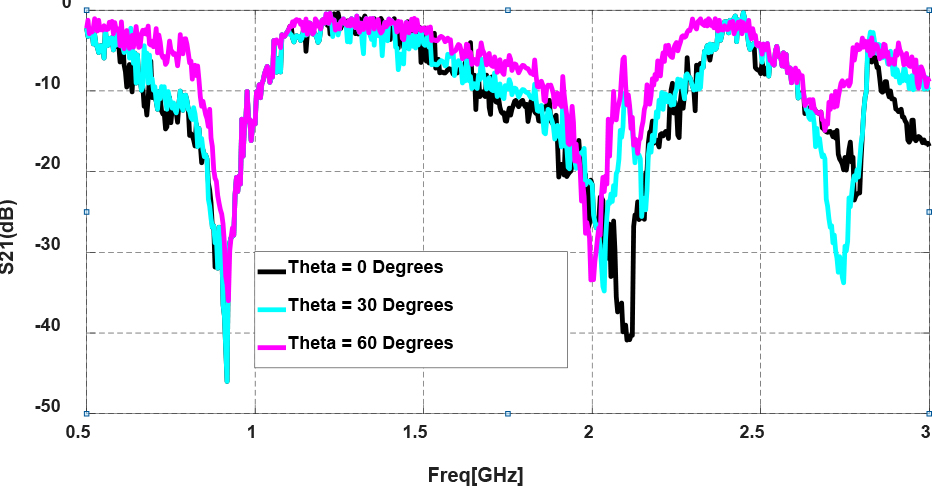
Figure 12: Measured transmission coefficient ( ) at different incidence angles for TM polarization.
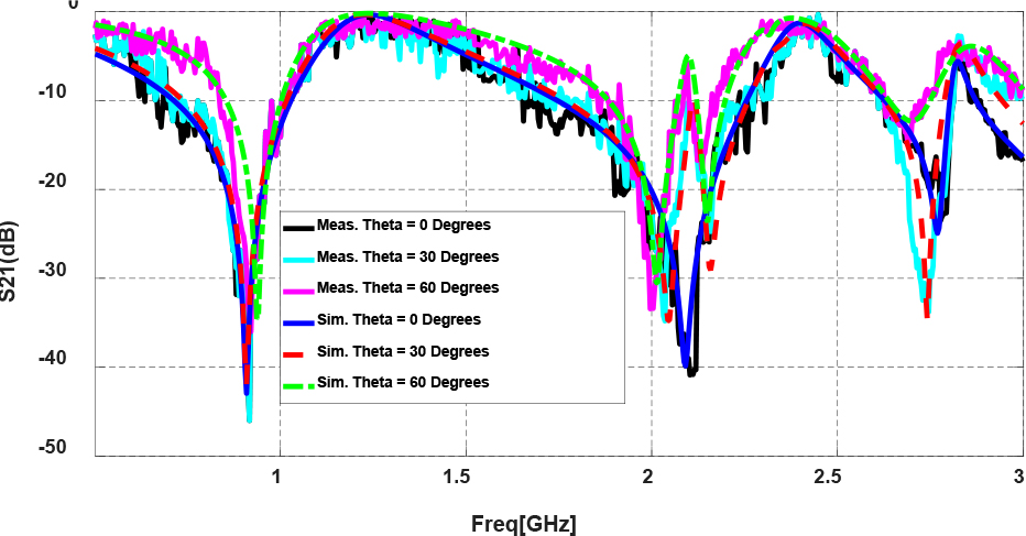
Figure 13: Measured and simulated transmission coefficient ( ) at different incidence angles for TM polarization.
On comparing measurement and simulation results, it can be seen that for both TE and TM polarizations, measurements and simulations yield similar results, i.e., the FSS has a stable frequency behavior while the incident wave’s angle ranges from 0 to 60, and more than 20 dB of attenuation is observed in the IMT-Advanced bands.
Figure 14 shows surface currents for IMT-Advanced mobile communication system resonant frequencies of 800, 900, 1800, 2100, and 2600 MHz. In the figure, we can see that for each different resonant frequency, surface currents of varying magnitudes occur on different surface elements.
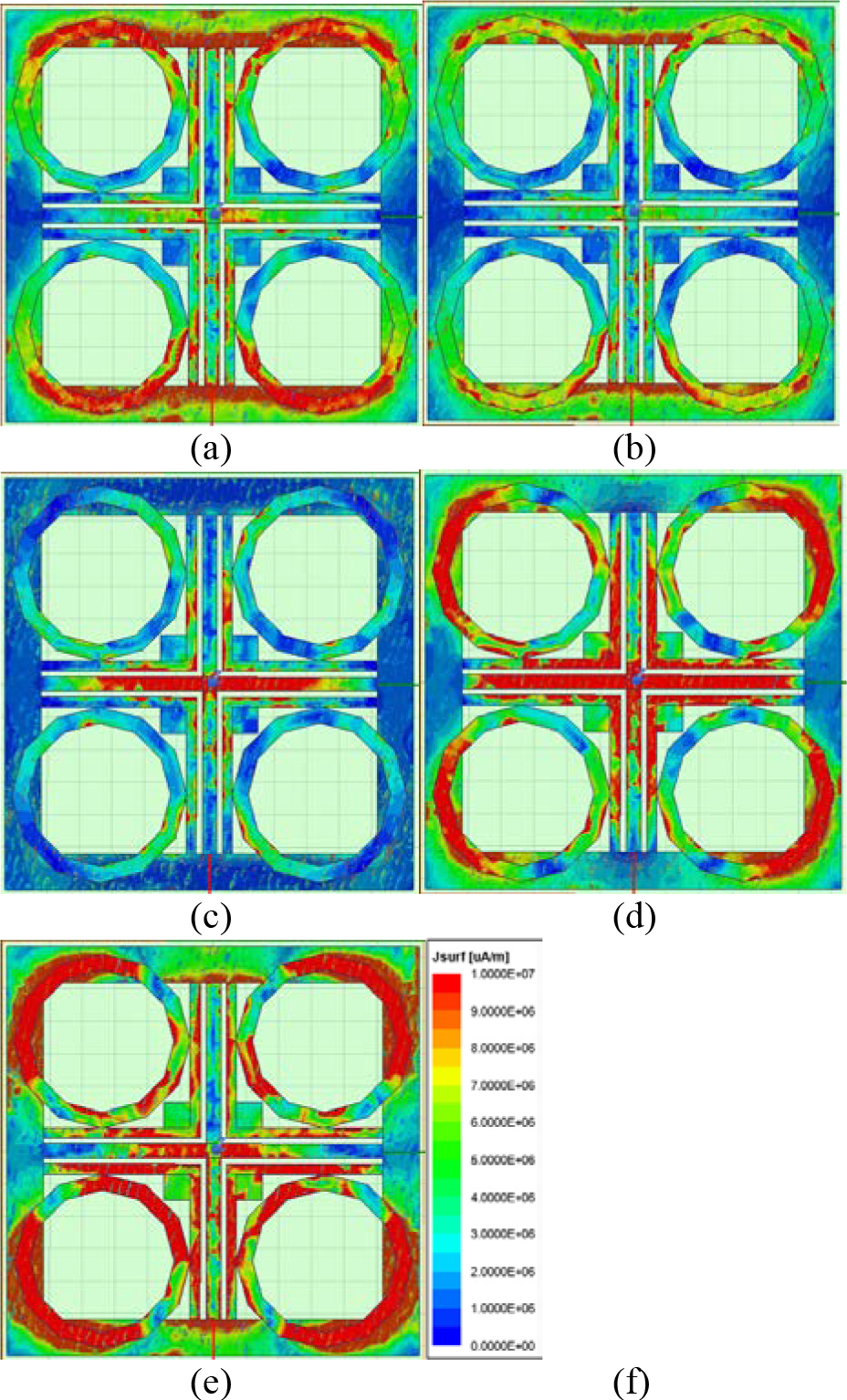
Figure 14: FSS surface currents. Notice how resonance peaks differ for patches at each 4G frequencies: (a) surface current at 800 MHz; (b) surface current at 900 MHz; (c) surface current at 1800 MHz; (d) surface current at 2100 MHz; (e) surface current at 2600 MHz; (f) scale.
IV. CONCLUSION
A novel double-layer low-profile multiband frequency selective surface (FSS) for a 4G IMT-Advanced mobile communication system has been designed in this research. The suggested FSS performed admirably as a band-stop filter, resonating at frequencies of 800, 900, 1800, 2100, and 2600 MHz. For TE and TM polarizations at each target frequency band, simulations and experiments were carried out while the incoming wave angle varied from 0 to 60. A double layer FSS was used to achieve the requisite minimum attenuation of 10 dB for large oblique incidence angles throughout all frequency bands. By reducing the thickness of the FSS and using sub-wavelength periodic structures, the design became low-profile and reacted as a higher order band-stop response with minimal sensitivity to incident wave angles.
REFERENCES
[1] B. Döken and M. Kartal, “Triple band frequency selective surface design for global system for mobile communication systems,” IET Microw. Antennas Propag., vol. 10, no. 11, pp. 1154-1158, Apr. 2016.
[2] R. Ma, Q. Guo, C. Hu, and J. Xue, “An improved WiFi indoor positioning algorithm by weighted fusion,” Sensors, vol. 15, pp. 21824-21843, 2015.
[3] F. C. G. da Silva Segundo and A. L. P. S. Campos, “Compact frequency selective surface with dual band response for WLAN applications,” Microwave and Optical Technology Letters, vol. 57, no. 2, pp. 265-268, 2015.
[4] G. H. Sung, K. W. Sowerby, M. J. Neve, and A. G. Williamson, “A frequency-selective wall for interference reduction in wireless indoor environments,” IEEE Antennas and Propag. Mag., vol. 48, no. 5, pp. 29-37, Oct. 2006.
[5] S. Armour, A. Doufexi, B. S. Lee, A. Nix, and D. Bull, “The impact of power limitations and adjacent residence interference on the performance of WLANs for home networking applications,” IEEE Trans. Consumer Electron., vol. 47, no. 3, pp. 502-511, 2001.
[6] S. M. A. M. H. Abadi, M. Li, and N. Behdad, “Harmonic-suppressed miniaturized-element frequency selective surfaces with higher order bandpass responses,” IEEE Trans. on Antennas Propag., vol. 62, no. 5, pp. 2562-2571, May 2014.
[7] G. Meng and N. Behdad, “A dual-band, inductively coupled miniaturized-element frequency selective surface with higher order bandpass response,” IEEE Trans. on Antennas Propag., vol. 64, no. 8, pp. 3729-3734, August 2016.
[8] G. Schennum, “Frequency-selective surfaces for multiple-frequency antennas.,” Microwave Journal, vol. 16, no. 5, pp. 55-57, 76, 1973.
[9] C. Gu, B. S. Izquierdo, S. Gao, J. C. Batchelor, E. A. Parker, and F. Qin, “Dual-band electronically beam-switched antenna using slot active frequency selective surface,” IEEE Trans. on Antennas Propag., vol. 65, no. 3, pp. 1393-1398, Mar. 2007.
[10] B. A. Munk, Frequency Selective Surfaces: Theory and Design, John Wiley & Sons, New York, 2000.
[11] C. J. Davenport, J. M. Rigelsford, J. Zhang, and H. Altan, “Periodic comb reflection frequency selective surface for interference reduction,” Loughborough Antennas & Propagation Conference (LAPC), pp. 615-618, 2013.
[12] E. F. Kent, B. Doken, and M. Kartal, “A new equivalent circuit based fss design method by using genetic algorithm,” 2nd International Conference on Engineering Optimization, 2010.
[13] M. Philippakis, C. Martel, D. Kemp, R. Allan, M. Clift, S. Massey, S. Appleton, W. Damerell, C. Burton, and E. Parker, “Application of FSS structures to selectively control the propagation of signals into and out of buildings,” Ofcom ref. AY4464A,2004.
[14] C. Mias, C. Tsakonas, and C. Oswald, “An investigation into the feasibility of designing frequency selective windows employing periodic structures, (Ref. AY3922),” Final Report for the Radio Communications Agency, Nottingham Trent University, 2001.
[15] I. Bardi, R. Remski, D. Perry, and Z. Cendes, “Plane wave scattering from frequency-selective surfaces by the finite-element method,” IEEE Transactions on Magnetics., vol. 38, no. 2, 641-644, 2002.
[16] M. Kominami, H. Wakabayashi, S. Sawa, and H. Nakashima, “Scattering from a periodic array of arbitrary shaped elements on a semi infinite substrate,” Electronics and Communications in Japan (Part I: Communications), vol. 77, no. 1, 85-94, 1994.
[17] M. Idrees, S. Buzdar, S. Khalid, M. A. Khalid, “A miniaturized polarization independent frequency selective surface with stepped profile for shielding applications,” Applied Computational Electromagnetics Society (ACES) Journal, vol. 31, no. 5, pp. 531-536, 2016.
[18] H. Ahmad, M. Rahman, S. Bashir, W. Zaman, and F. C. Seman, “Miniaturized frequency selective radome operating in the X-Band with wideband absorption,” Applied Computational Electromagnetics Society (ACES) Journal, vol. 34, no. 12, pp. 1915-1921, Dec. 2019.
[19] B. Döken and M. Kartal, “Dual layer convoluted frequency selective surface design in the 2.4 GHz and 5.8 GHz ISM bands,” Applied Computational Electromagnetics Society (ACES) Journal, vol. 33, no. 4, pp. 413-418, 2021.
[20] Z. Yu and W. Tang, “A third-order bandpass three-dimensional frequency selective surface with multiple transmission zeros,” Applied Computational Electromagnetics Society (ACES) Journal, vol. 35, no. 12, pp. 1548-1555, 2020.
[21] Ş. Balta and M. Kartal, “A novel multilayer multiband frequency selective surface for IMT advanced 4G mobile phone service and airborne radar systems,” 9th International Conference on Recent Advances in Space Technologies (RAST), pp. 527-531, 2019.
BIOGRAPHIES

Şakir Balta was born in 1986. He received the B.S. degree in electronics and communication engineering in 2009 and the M.S. degree in 2013. He is currently working toward the Ph.D. degree in electronics and communication engineering with Istanbul Technical University, Istanbul, Turkey.
He is still a Chief Researcher with TÜBİTAK (The Scientific and Technological Research Council of Turkey), Kocaeli, Turkey. His research interest includes antenna and FSS design, RF and microwave design engineering, circuit design, logic design, FPGAs (Field Programmable Gate Arrays), as well as modeling, design, simulations, and analysis, and CAD techniques in high frequency region.

Mesut Kartal received the M.S. degree in 1993 and the Ph.D. degree in 2000.
He is still a Professor with Istanbul Technical University, Department of Electronics and Communication Engineering. His research interest includes remote sensing, antenna and FSS design, inverse problems, RF and microwave design engineering, as well as modeling, design, simulations, and analysis, and CAD techniques in high frequency region.
ACES JOURNAL, Vol. 37, No. 4, 420–427.
doi: 10.13052/2022.ACES.J.370407
© 2021 River Publishers