Analysis of Symmetric Two and Four-coil Magnetic Resonant Coupling Wireless Power Transfer
Azuwa Ali, Mohd Najib Mohd Yasin, Ali Hanafiah Rambe, Ismahayati Adam, Nurulazlina Ramli, Hasliza A. Rahim, Thennarasan Sabapathy, Mohd Natashah Norizan, and Sharizal A. Sobri
Faculty of Electrical Engineering Technology, Universiti Malaysia Perlis, Pauh Putra Campus, 02600 Arau, Perlis, Malaysia
azuwa@unimap.edu.my
Faculty of Electronic Engineering Technology, Universiti Malaysia Perlis (UniMAP), Pauh Putra Campus, 02600 Arau, Perlis, Malaysia
najibyasin@unimap.edu.my, ismahayati@unimap.edu.my, haslizarahim@unimap.edu.my, thennarasan@unimap.edu.my mohdnatashah@unimap.edu.my
Department of Electrical Engineering, Universitas Sumatera Utara, Medan, Indonesia
ali3@usu.ac.id
Faculty of Engineering and the Built Environment (FoEBE), SEGI University, Kota Damansara, 47810 Petaling Jaya, Selangor, Malaysia
azlinaramli@segi.edu.my
Advanced Material Research Cluster, Faculty of Bioengineering and Technology, Universiti Malaysia Kelantan, Jeli Campus, 17600 Jeli, Kelantan, Malaysia
sharizal.s@umk.edu.my
Submitted On: August 31, 2021; Accepted On: April 18, 2022
Abstract
This study examined the efficiency of power transfer for two-coil and four-coil spiral magnetic resonant coupling wireless power transfer (WPT) using distance to coil diameter (D/d) ratio and reflection coefficient, S value. Adding resonators reduced the total resistance in the two-coil WPT system while increasing the S values of the whole system. A same-size spiral coil was proposed for the system and simulated using computer simulation technology (CST). A prototype with similar specifications for a four-coil design was implemented for verification. The proposed method yielded an optimal efficiency of 76.3% in the four-coil system, while the two-coil WPT yielded a 23.2% efficiency with a 1.33 D/d ratio.
Keywords: Two-coil, four-coil, resonator, wireless power transfer.
I. INTRODUCTION
The wireless power transfer (WPT) technology uses a physical electromagnetic field to transmit energy. WPT was initiated by Nikola Tesla between 1891 and 1904. Tesla’s WPT generated high alternating current using inductive coupling. In his experiment, Tesla lit three lamps at a 100-ft transfer distance using “Tesla Tower” [1]. Today, WPT is highly sought after for charging small electronic devices.
In 2007, the Massachusetts Institute of Technology (MIT) powered a 60-W light bulb ata 2-m distance from a transmitting coil via WPT [2]. This technology continued to expand in 2012 as the US Transportation Department used WPT to charge vehicles on railways and highways [4]. Studies on WPT are undertaken across many countries, particularly in the US, South Korea, China, and Japan [3, 4]. The ever-increasing demand for modern electronic devices (e.g., electric vehicles, mobile phones, and smart watches) becomes a driver for WPT, especially after its adoption for multiple applications.
Despite its high demand, WPT cannot transfer power over a long distance. Deterioration of power transfer efficiency (PTE) when distances exceed the coil diameter [21, 23]. This drawback may be resolved by incorporating an impedance matching network or inserting more loops except for a bulky outlook [2].
This study assessed the PTE of magnetic resonant coupling (MRC) WPT using two-coil and four-coil systems of the same size but without variable impedance matching. This MRC system consisted of two independent coils,i.e., receiver and transmitter resonating together. Both coils were wirelessly separated by air. Identifying the attributes of the magnetic field was essential since MRC depended on the magnetic coupling. Specifically, the magnetic field would substantially affect the coupling coefficient, mutual inductance, and, eventually, the overall MRC performance.
Apart from the design and shape, adding a resonator to each of the two coils was essential to enhance the system’s efficiency [22, 24]. Adding two or multiple resonators generated a magnetic field and flux distribution of higher values, thus affecting system efficiency. A circular spiral coil shape was selected [7, 11, 13, 14, 20] in this study due to its exceptional performance. With less resistance,this spiral coil improved the mutual inductance value. Adding a resonator to the transmitter and receiver would increase the intensity of the magnetic field MRC, improving the power transfer capability. Enhancing the power transfer capability would increase the coverage of effective distance. Recognizing the importance of embedding a resonator to MRC, this study incorporated two and four spiral coils to assess their effects on MRC performance based on S values using via computer simulation and experimental validation.
II. MUTUAL INDUCTANCE, REFLECTION, AND TRANSMISSION COEFFICIENT
Mutual inductances happen when the magnetic flux from a transmitter coil cuts across the receiver coil to induce the voltage and current in the receiver coil. In some cases, the leakage inductance exceeds the mutual inductance in a loosely coupled system, reducing the magnetizing flux [1, 3].
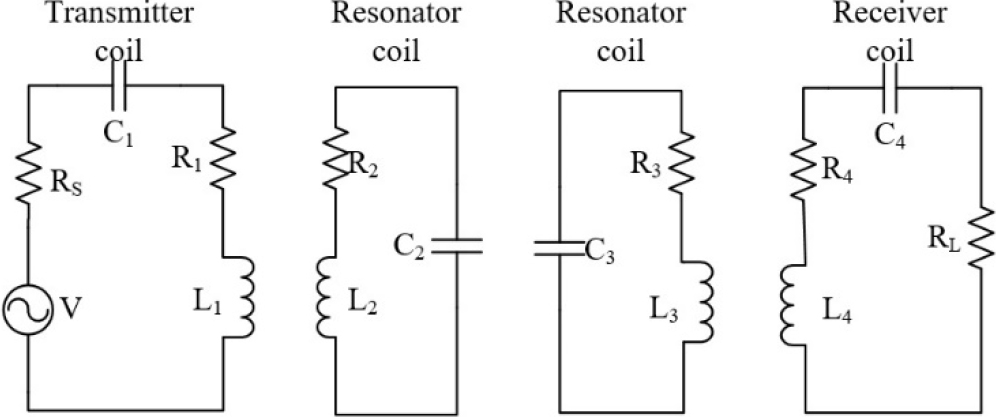
Figure 1: The equivalent circuit model of a four-coil system.
Figure 1 shows the resonant coupled four-coil system as an analogous circuit model using lumped parameters (L, C, and R). The interactions of the transmitter and receiver coils are the most crucial for power transfer, and the efficiency is virtually determined by the distance between them. When all four coils resonate together, their inductive and capacitive reactance become equal, allowing the receiver coil to cut the oscillating field created in the transmitter coil sufficiently to transmit the power to the load. Therefore, the mutual inductance, M, and the coupling coefficient, k, are related by following equation:
| (1) |
where L is the inductance of the receiver coil and L is the inductance of the transmitter coil. Higher M means higher efficiency of the MRC. Meanwhile, the reflection coefficient, S, denotes the amount of power reflected from the receiver to the transmitter, whereas the transmission coefficient, S, signifies the amount of power transmitted to the receiver from the transmitter. Therefore, a lower return loss generates a higher S and promotes more power transfer.
The S parameter [eqn(2)] below is used to compute PTE
| (2) |
| (3) |
Eqn (2) denotes S in dB value but converted to percentage in eqn (3) to compare performance. Therefore, this study measured S, inductance, and k of the system for investigating the performance of MRC with two-coil and four-coil WPTs. Several methods are used to determine inductance. They include Maxwell formula, Grover’s method, Neumann’s integrals, and finite element analysis (FEA) [1].
Several authors [3] attempted to derive accurate equations fork, yielding complicated formulas due to the complexity of the coupling mechanism in multi-turn structure [1, 3]. In general, knowing the frequency range of the application is crucial. At very low frequencies, the capacitive (electric) coupling also affects k [2]. Thus, a full-wave simulation remains essential for predicting the whole system’s performance even thoughM and kcould be computed [using eqn(1)–(3)].
In this study, two software packages were used. The first was the FEA software known as An soft Maxwell (version x, name of developer, country). It determined k and M. The second one was the computer simulation technology (CST) software (version x, name of developer, country). It determined the S value. These software packages were used to model the MRC for the two-coil and four-coil in simulation in a three-dimensional (3D) environment. The FEA software was chosen because this technique did not require complex manual calculation while yielding consistent and reliable outputs for different types of systems.
III. METHODOLOGY
The comparative study impact of resonator on the performance of WPT was compared using An soft Maxwell. This software assessed the coupling factor effect on the WPT system. Figure 2 shows the plane view of the coil design for the two-coil and four-coil systems.
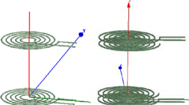
Figure 2: The simulation of two-coil and four-coil systems using Ansoft Maxwell.

Figure 3: The proposed geometry of the spiral coil.
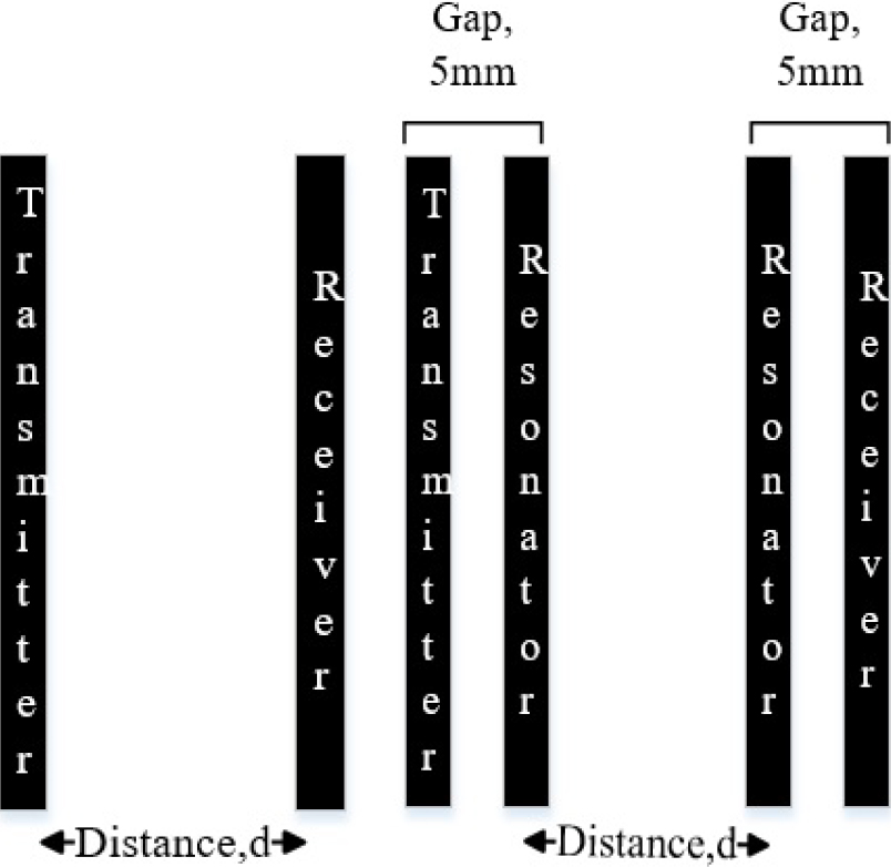
Figure 4: The distance measurement for the two-coil and four-coil systems.
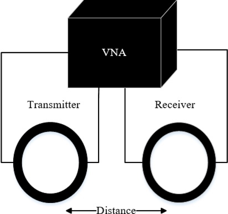
Figure 5: The measurement setup.
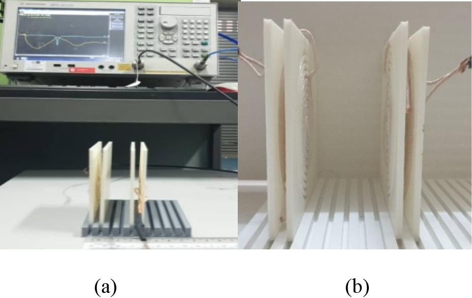
Figure 6: The measurement setup for the four-coil MRC.
Table 1 gives the specifications upon which coils were designed.
Table 1: The proposed coil parameters for the simulation
| Coil parameter (cm) | |
|---|---|
| Wire diameter, d | 0.1 |
| Coil progress/gap, g | 0.4 |
| Inner radius, R | 0.5 |
| Number of turns, n | 5 |
The radius of the wire and the coil thickness followed the exact Litz wire for small applications. Following the study of [11], no additional capacitor was added to tune the frequency of these coils for simultaneous resonance. PTE was compared with the CST software to assess the resonators’ performance.
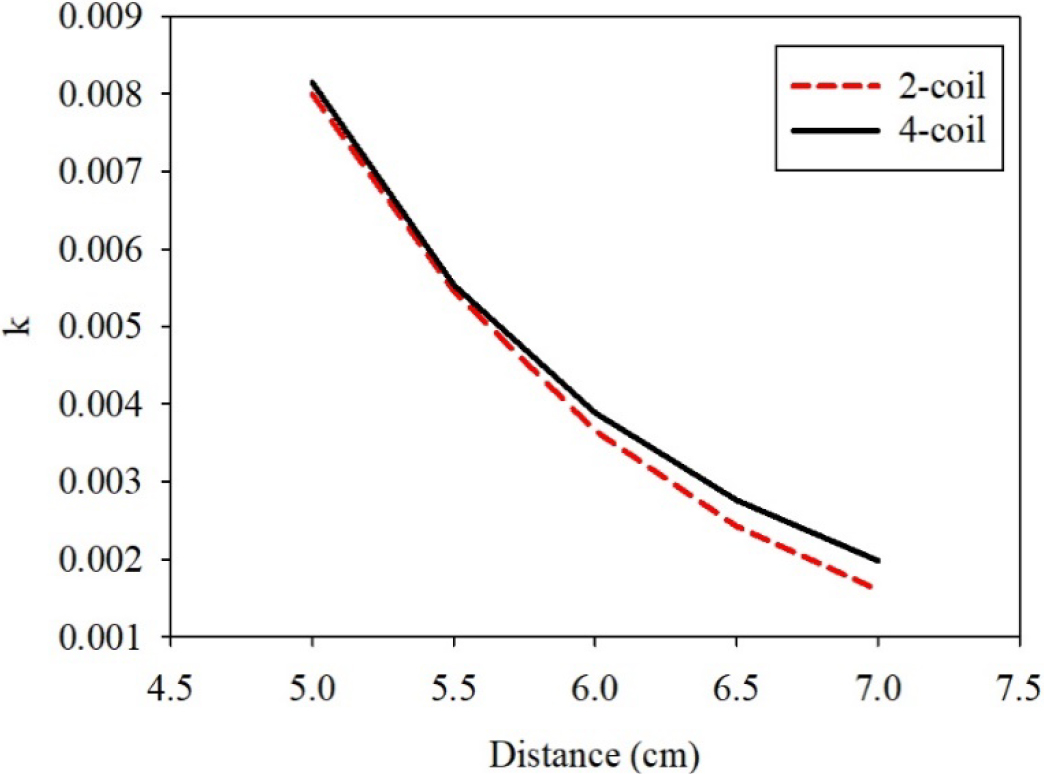
Figure 7: Comparison of the coupling coefficient (k) for the two-coil and four-coil WPTs.
Figure 3 shows the geometry of the spiral coil geometry based on the parameters of Table 1 parameter use Litz wire as the coil prototype. Figure 4 shows the distance measurements for the two- and four-coil systems for simulations and experiments. For the four-coil system, the distance was measured from the transmitter’s resonator to the receiver’s resonator. The distance between the coils and the resonator for the transmitter and receiver was set at a maximum of 5 mm, and the distance varied from 5 to 7cm.
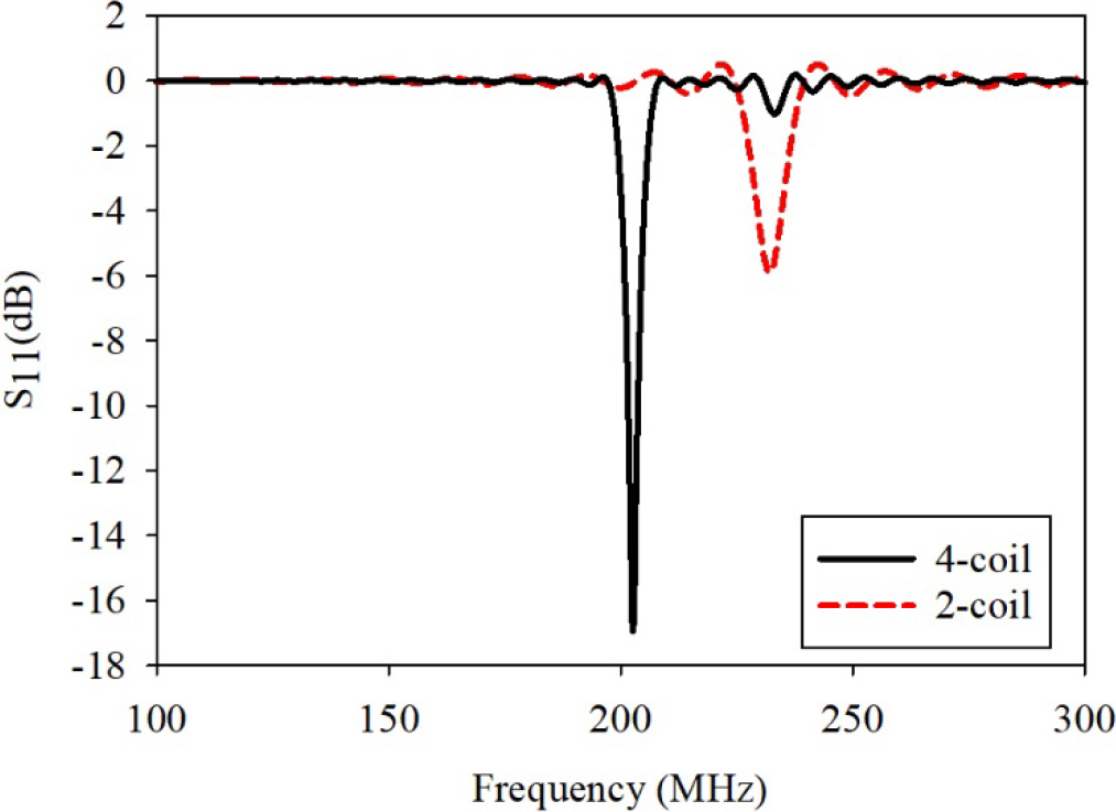
Figure 8: The S parameter.
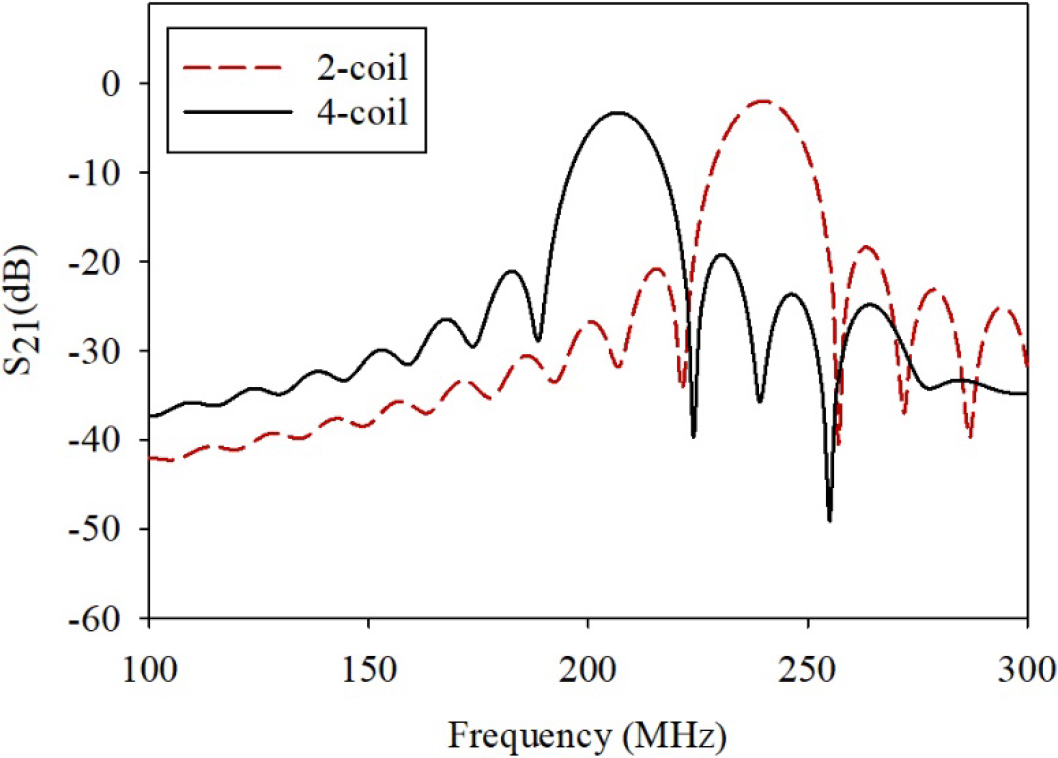
Figure 9: S parameter.
Figure 5 shows the measurement setup for the experiments. The vector network analyzer (VNA) was connected to the transmitter and receiver for measuring S and S.
The distance from the receiving to the transmitting coils was altered manually. Values of S were recorded based on the distance variation. The performance of each system was experimentally evaluated using the setup of Figure 6.
IV. RESULTS AND DISCUSSION
Figure 7 shows the simulation of k for the two- and four-coil WPTs based on eqn (1). The values of k decreased exponentially when the distance increased. In general, the four-coil WPT performed better than the two-coil WPT.
The two-coil system results served as reference values to compare the improvement before and after incorporating the resonator. The CST material was composed of pure copper. The distance varied from 5 to 7 cm with a 0.5-cm increment.
Figures 8 and 9 show the simulation values of S and S for the two- and four-coil systems, respectively. In general, the four-coil WPT performed better than the two-coil system.
Figure 10 shows the simulation outcomes for both systems,yielding a 25.8% efficiency for the four-coil and a 16.0% efficiency for the two-coil system at a 7-cm distance. The four-coil system’s efficiency increased by 9.8%, indicating that the resonator coil had enhanced the performance of the MRC system.
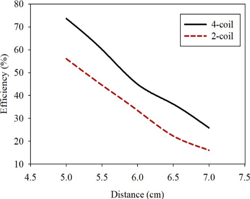
Figure 10: Simulation results of the two-coil and four-coil systems.
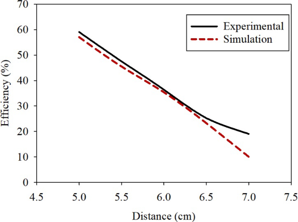
Figure 11: Simulation and experimental results for the two-coil system.
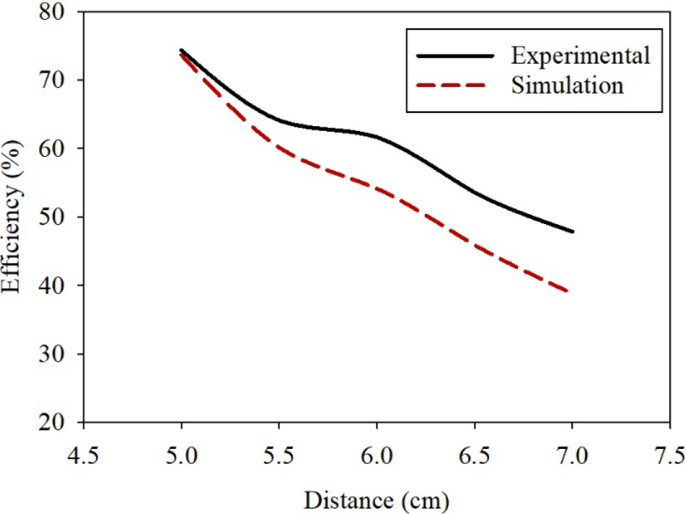
Figure 12: Simulation and experimental results for the four-coil system.
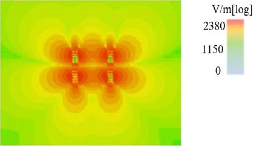
Figure 13: The cross-sectional distribution of the electric field (E-field) at a 5-cm distance.
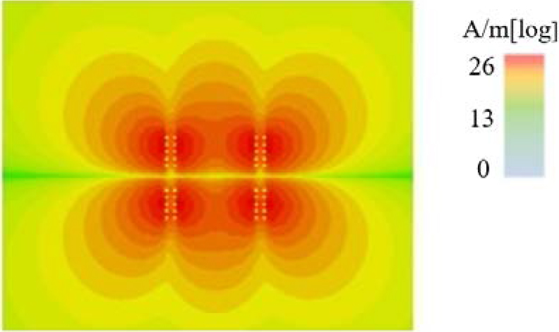
Figure 14: The cross-sectional distribution of the magnetic field (H-field) at a 5-cm distance.
An experimental model was built to verify the accuracy of modeling. The coil was measured using VNA, and the S value was recorded. The efficiency performance plotted against distance is illustrated in Figures 11 and 12 which show the efficiency performance versus the distance for the two- and four-coil systems, respectively. The system’s efficiency improved by 24% when the four-coil WPT was used. The efficiency exceeded 50% at a 6.5-cm distance, indicating that this design performed better even when the distance exceeded the coil size. This design performed better than several other systems (Table 2). In general, the efficiency deteriorates rapidly, not exceeding 0% if the ratio of distance (D) to coils is higher than the coil diameter, d [13]. Thus, PTE decreased substantially when Dd.
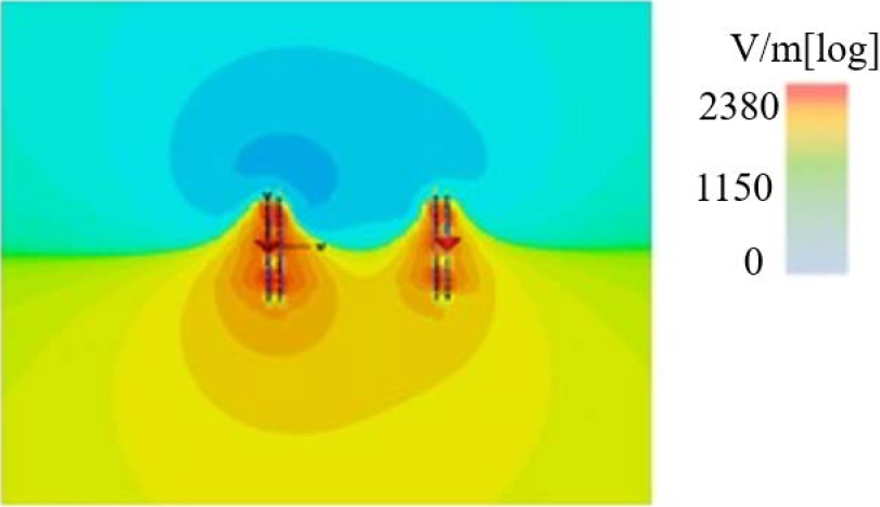
Figure 15: The cross-sectional distribution of the electric field (E-field) view at a 7-cm distance.
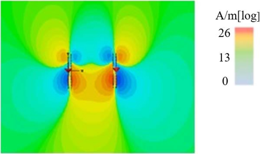
Figure 16: The cross-sectional distribution of the magnetic field (H-field) view at a 7-cm distance.
The coil used in the simulation consisted of copper, while the Litz wire was used in the experimental validation. Consequently, the simulation and the actual measurements varied slightly. A higher PTE for a longer distance was probably because the Litz wire could reduce the skin effect [11, 13], increasing the magnetic field.
Figures 13 and 14 show the cross-sectional distribution of the electric field (E-field) and magnetic field (H-field) of the four-coil system, respectively, based on the CST simulation at a 5-cm distance. Strong E-field and H-field were distributed and concentrated near the transmitter and receiver coils with the resonator.
Figures 15 and 16 show the cross-sectional distribution of the E-field and H-field of the four-coil system, respectively, based on the CST simulation at a 7-cm distance. A lower distribution of E-field and H-field indicated weak or low PTE.
Table 2: Comparison of the proposed design with related previous works
| No | Efficiency and distance, D(cm) | Coil type and size, (cm) | Resonator type and size, (cm) | Advantages/ Shortcoming | |
| 1. (J. Zhang & Cheng, 2016) | 30 cm distance with 55% PTE | Helical, 11 turns, 31.5 |
Helical, 11 turns, 31.5 |
D/d = 0.95 | Big, bulky design |
| 2. (Chung, Lee, Kang, & Park, 2016) | 25cm distance with 80% PTE | Helical, 30 |
Helical, 30 |
D/d = 0.833 | Resonator position varies to 15cm and 25cm from the transmitter PTE value not mentioned |
| 3. (Dang & Qahouq, 2015) | 50 cm distance with 85% PTE | Spiral, 10 turns, 40 |
Spiral, 10 turns, 40 |
D/d = 1.25 | Big design |
| 4. (Moghadam & Zhang, 2016) | 100cm distance with 60% PTE | Planarized, 14 |
Planarized, 60 |
D/d = 1.67 | Big design |
| 5. (Jonah, Member, Georgakopoulos, & Member, 2013) | 10 cm distance with 56.4% PTE | Circular copper, 10 |
Circular copper, 10 |
D/d = 1 | Vary the position of resonator |
| 6. (C. Zhang, Zhong, Liu, & Hui, 2014) | 60cm distance with resonator in the middle 53.1% PTE, closer to receiver coil 69.3% PTE | Helical, 11 turns, 30 |
Helical, 11 turns, 30. |
D/d = 2 | Big, bulky design Resonator position 0.38 cm near to receiver coil |
| 7. (Jolani, Chen, & Yu, 2015) | 10cm distance with 83% PTE | Planar rectangular spiral, 2 turns, 5.9 |
Planar rectangular spiral, 5.9 |
D/d=1.67 | 3-layer planar resonator and loaded with capacitor |
| 8. (Liu & Wang, 2016) | 45 cm distance with 51.3% PTE | Helical, 11 turns, 11 |
Helical, 11 turns, 11 |
D/d = 4 | Resonator position in the middle of transmitter and receiver. Big, bulky design with wire height 5.8cm |
| 9. (Chin, Chung, Shuenn, Soon, &Lih, 2017) | 1 cm distance with 19.1% PTE | Printed spiral coil, 3 turns, 0.5 |
Helical, 3 turns,0.5 |
D/d = 2 | Efficiency is very low Bulky design Wireless implantable application |
| 10. (Chen & Zhang, 2015) | 15.2 cm distance with 70% PTE | Spiral, 10 turns, 5.5 |
Spiral, 10 turns, 12.5 |
D/d=1.22 | Big design |
| 11. This work | 7 cm distance with 76.34% PTE | Spiral, 5 turns Transmitter= Receiver= 5 |
Spiral, 5 turns Resonator= 5 |
D/d=1.4 | Same size of transmitter, receiver and resonator Resonator position is close to transmitter and receiver |
The distance as a ratio of the coil diameter using the proposed design was 1.33 higher than the experimental result in the ratio (Table 2). The studies of [8] and [10] also yielded a higher ratio, but their bulky design was unsuitable for WPT applications. Likewise, the study of [11] yielded a higher ratio,but the system was optimized with a capacitor-loaded WPT with the resonator placed between the transmitter and receiver coils in [6]. Such an implementation is impractical for the actual application. By contrast, in this study, no capacitor was added to reduce the complexity in hardware implementation, thus yielding a small and compact design. Besides, both resonator coils in this study were similar in size, with the transmitter and receiver coils positioned close to both receiver and transmitter coils. The results appeared promising,with a consistent resonant frequency recorded despite the varied distance, along with improved PTE.
V. CONCLUSION
The design proposed in this study suits the MRC WPT concept with additional benefits in size and simplicity. This study recorded MRC WPT with a high PTE of 76.3% at a transfer distance exceeding 1.33 times the coil diameter. Overall,incorporating a resonator increased the PTE efficiency,enhancing the distance beyond the coil diameter, particularly when compared with the two-coil system.
ACKNOWLEDGMENT
This study was supported by Universiti Malaysia Perlis (UniMAP) and the Ministry of Higher Education (MoHe) under a Grant Number FRGS 9003-00850 (FRGS/1/2020/ICT09/UNIMAP/02/3).
REFERENCES
[1] N. Tesla, “The transmission of electrical energy without wires as a means for furthering peace,” Electrical World and Engineer, pp. 21, 2005.
[2] L. Sun, D. Ma, and H. Tang, “A review of recent trends in wireless power transfer technology and its applications in electric vehicle wireless charging,” Renewable and Sustainable Energy Reviews, vol. 91, pp. 490-503, 2018.
[3] H. Wang and X. Li, “Review and research progress of wireless power transfer for railway transportation,” Transactions on Electrical and Electronic Engineering (IEEJ), vol. 4, no. 14, pp. 475-484, 2019.
[4] A. B. D. Arthur, “Review and evaluation of wireless power transfer (WPT) for electric transit applications,” FTA Report No. 0060; FTA-0060,2018.
[5] X. Chen and G. X. Zhang, “Middle range wireless power transfer systems with multiple resonators,” Journal of Central South University, vol. 22, no. 6, pp. 2127-2136, 2015.
[6] C. Y. Do, C. Y. Lee, H. Kang, and Y. G. Park, “Design considerations of superconducting wireless power transfer for electric vehicle at different inserted resonators,” IEEE Transactions on Applied Superconductivity, vol. 26, no. 4, pp. 1-5, Jun. 2016.
[7] Z. Dang and J. A. A. Qahouq, “Range and misalignment tolerance comparisons between two-coil and four-coil wireless power transfer systems,” Applied Power Electronics Conference and Exposition (APEC)IEEE, pp. 1234-1240, 2015.
[8] M. R. V. Moghadam and R. Zhang, “Multiuser wireless power transfer via magnetic resonant coupling: performance analysis, charging control, and power region characterization,” IEEE Transactions on Signal and Information Processing over Networks, vol. 2, no. 1, pp. 72-83, 2016.
[9] O. Jonah, S. Member, S. V. Georgakopoulos, and S. Member, “Wireless power transfer in concrete via strongly coupled magnetic resonance,” IEEE Transactions on Antennas and Propagation, vol. 61, no. 3, pp. 1378-1384, 2013.
[10] C. Zhang, W. Zhong, X. Liu, and S. Y. R. Hui,, “A fast method for generating time-varying magnetic field patterns of mid-range wireless power transfer systems,” IEEE Transactions on Power Electronics, vol. 30, no. 3, pp. 1513-1520, 2015.
[11] F. Jolani, Z. Chen, and Y. Yu, “Enhanced planar wireless power transfer using strongly coupled magnetic resonance,” Electronics Letters, 51(2), vol. 13, pp. 1648-1651, 2014.
[12] X. Liu and G. Wang, Senior Member, IEEE, “A novel wireless power transfer system with double intermediate resonant coils,” IEEE Transactions on Industrial Electronics, vol. 63, no. 4, pp. 2174-2180, 2016.
[13] C. Yang, C. Chang, S.-Y. S. Chang, and L. Chiou, “Efficient four-coil wireless power transfer for deep brain stimulation,” IEEE Transactions on Microwave Theory and Techniques, vol. 65, no. 7, 2017.
[14] X. Chen and G. X. Zhang, “Middle range wireless power transfer systems with multiple resonators,” Journal of Central South University, vol. 22, pp. 2127-2136, 2015.
[15] N. J. Grabham, Y. Li, L. R. Clare, B. H. Stark, and S. P. Beeby, “Fabrication techniques for manufacturing flexible coils on textiles for inductive power transfer,” IEEE Sensors Journal, vol. 18, no. 6, pp. 2599-2606, 2018.
[16] D. Kim, J. Kim, and Y. Park, “Optimization and design of small circular coils in a magnetically coupled wireless power transfer system in the megahertz frequency,” IEEE Transactions on Microwave Theory and Techniques, vol. 64, no. 8, pp. 2652-2663, 2016.
[17] T. Mizuno, T. Ueda, S. Yachi, R. Ohtomo, and Y. Goto’, “Dependence of efficiency on wire type and number of strands of litz wire for wireless power transfer of magnetic resonant coupling,” IEEJ Journal of Industry applications, vol. 3, pp. 35-40, 2014.
[18] B. H. Waters, B. J. Mahoney, G. Lee, and J. R. Smith, “Optimal coil size ratios for wireless power transfer applications,” IEEE International Symposium on Circuits and Systems (ISCAS), pp. 2045-2048, 2014.
[19] J. P. K. Sampath and A. Alphonesand Hitoshi Shimasaki, “Coil design guidelines for high efficiency of wireless power transfer (WPT),” IEEE Region 10 International Conference TENCON, pp. 726-729, 2016.
[20] M. A. Houran, X. Yang, and W. Chen, “Magnetically coupled resonance WPT?: Review of compensation topologies, resonator structures with misalignment, and EMI diagnostics,” Electronics vol. 7, no. 11, pp. 296, 2018.
[21] S. Y. R. Hui, W. Zhong, and C. K. Lee, “A critical review of recent progress in mid-range wireless power transfer,” IEEE Trans. Power Electron., vol. 29, no. 9, pp. 4500-4511, 2013.
[22] A. Kurs, A. Karalis, R. Moffatt, J. D. Joannopoulos, P. Fisher, and M. Solja, “Wireless power transfer via strongly coupled magnetic resonances,” Science, vol. 317, pp. 83-86, 2017.
[23] D. Seo, “Comparative analysis of two- and three-coil WPT systems based on transmission efficiency,” IEEE Access, vol. 7, pp. 151962-151970, 2019.
[24] X. Zhang, S. L. Ho, and W. N. Fu, “Quantitative design and analysis of relay resonators in wireless power transfer system,” IEEE Transactions on Magnetics, vol. 48, no. 11, pp. 4026-4029, 2012.
BIOGRAPHIES

Azuwa Ali received B.Eng. degree in electrical and electronic engineering (Computer System) in 2004 from Universiti Teknologi Petronas (UTP) and the master’s degree in electrical electronic engineering (communication & computer) in 2007 from Universiti Kebangsaan Malaysia (UKM).
She is a Lecturer with the Faculty of Electrical Engineering Technology, Universiti Malaysia Perlis (UniMAP). Her current research work includes the development of renewable harvesting system and wireless communication.

Mohd Najib Mohd Yasin United Kingdom, and the Ph.D. degree from the University of Sheffield, Sheffield, U.K., in 2007 and 2013, respectively.
Since 2013, he has been a Lecturer withthe Faculty of Electronic Engineering Technology, Universiti Malaysia Perlis (UniMAP). His research interests include computational electromagnetics, conformal antennas, mutual coupling, wireless power transfer, array design, and dielectric resonator antennas.

Ali Hanafiah Rambe (Member, IEEE) was born in Medan, Sumatera Utara, Indonesia, in 1978. He received the bachelor’s degree in telecommunication engineering from Universitas Sumatera Utara (USU), in 2003, the master’s degree from the University of Indonesia, in 2008, and the Ph.D. degree from USU, in 2014.
He is currently a Lecturer and a Researcher with the Department of Electrical Engineering, Faculty of Engineering, USU. His research interests include microstrip antennas, electronic telecommunication, and radar.

Ismahayati Adam received the bachelor’s degree in electrical-electronic and telecommunication engineering in 2006 and the M.Eng. degree in electronic telecommunication engineering in 2008 from Universiti Teknologi Malaysia (UTM). She received the Ph.D. degree in communication engineering from Universiti Malaysia Perlis, Malaysia, in 2018.
Since 2008, she has been with the Faculty of Electronic Engineering Technology, Universiti Malaysia Perlis (UniMAP) as a Lecturer. Her research interest includes antenna design, RF energy harvesting, mutual coupling, and wireless propagation.

Nurulazlina Ramli was born in Sri Aman, Sarawak, Malaysia, in 1984. She received theB.Eng. degree in electrical engineering (telecommunications) from the Universiti Teknologi Malaysia (UTM), Malaysia, in 2008. She pursued the M.Sc.degree in telecommunications and information engineering in 2011, and the Doctor of Philosophy degree in electrical engineering from Universiti Teknologi Mara (UiTM), Shah Alam, Malaysia, in 2015.She has been a Lecturer with the Faculty of Engineering, Built Environment, and Information Technology (FoEBEIT) at SEGi University, Malaysia, since September 2015. She is a Member of Institute of Electrical and Electronics Engineers (IEEE), a Graduate Member of the Institution of Engineers Malaysia (IEM), and a Registered Member of the International Association of Engineers (IAENG). Her research interests are in the areas of communication antenna design, reconfigurable/wearable antennas, electromagnetic radiation analysis, indoor/outdoor propagation modeling, dielectric resonator antenna, and wireless power transfers.

Hasliza A. Rahim received the bachelor’s degree in electrical engineering from the University of Southern California, Los Angeles, CA, USA, in 2003, the master’s degree in electronics design system from Universiti Sains Malaysia, Pulau Pinang, Malaysia, in 2006, and the Ph.D. degree in communication engineering from Universiti Malaysia Perlis, Perlis, Malaysia, in 2015. Hasliza A. Rahim In 2006, she joined the Faculty of Electronic Engineering Technology, Universiti Malaysia Perlis (UniMAP), as a Lecturer, where she is currently an Associate Professor. She is a Chartered Engineer, Professional Technologist, Research Fellow with the Advanced Communication Engineering (ACE) Centre of Excellence and Head of Bioelectromagnetics Group under ACE. Her research interests include wearable and conformal antennas, metamaterials, antenna interaction with human body, on-body communications, green microwave absorbers, wireless body area networks, bioelectromagnetics, artificial intelligence (AI) optimization, and physical layer protocols for wireless communications.

Thennarasan Sabapathy received the B.Eng. degree in electrical telecommunication engineering from the Universiti Teknologi Malaysia, in 2007 and the M.Sc.Eng. degree from Multimedia University, Malaysia, in 2011. He pursued thePh.D. degree in communication engineering from Universiti Malaysia Perlis in 2014. He is currently an Associate Professor with the Faculty of Electronic Engineering Technology, Universiti Malaysia Perlis. His current research interests include antenna and propagation, millimeter-wave wireless communications, and fuzzy logic for wireless communications.

Mohd Natashah is a Senior Lecturer withthe Faculty of Electronic Engineering Technology (FTKEN), Universiti Malaysia Perlis (UniMAP), Malaysia. He received the bachelor’s degree in electronic engineering from UniMAP, Malaysia, in 2008, theM.Sc.degree in microelectronics from Universiti Kebangsaan Malaysia (UKM), Malaysia, in 2011, and the Doctor of Engineering degree in sustainable energy and environmental engineering from Osaka University, Japan. He is active in volunteering work with IEEE Malaysia Section, acting as the Senior Member of IEEE and a committee member of the IEEE Malaysia Section Sensors and Nanotechnology Joint Councils Chapter. He is a member of the Institution of Engineering and Technology (IET), United Kingdom, Graduate Engineer of the Board of Engineers Malaysia (BEM), Malaysia, Chartered Engineer of the Engineering Council, United Kingdom, and Professional Technologist of the Malaysia Board of Technologist (MBOT), Malaysia.

Sharizal A. Sobri is from the Faculty of Bioengineering and Technology, Universiti Malaysia Kelantan (UMK). He received the Ph.D. degree in mechanical engineering from the University of Manchester, U.K., and is currently one of the researchers in Advanced Material Research Cluster at the faculty. In January 2020, he was lucky to be chosen as a Fellow of CEO@FacultyProgramme 2.0 Cycle 3. He is proud that this time Huawei Malaysia has chosen him to fulfill his vision as an innovative leader. For six months, he was assigned to the Department of Public Affairs and Communication (PACD) and he had many incredible moments.
ACES JOURNAL, Vol. 37, No. 4, 497–506.
doi: 10.13052/2022.ACES.J.370415
© 2021 River Publishers