A Compact High Gain Wideband Metamaterial Antenna for Sub-6 GHz Applications
Ahmed A. Abbas and Balasem S. Samet
1Department of Electrical Engineering, Faculty of Engineering, University of Anbar, Anbar, Iraq
Ahmed.abbas@uoanbar.edu.iq, balasem.sumait@uoanbar.edu.iq
Submitted On: May 15, 2022; Accepted On: October 2, 2022
Abstract
This paper presents a design of high gain wideband antenna with metasurface for sub-6 GHz applications. The antennas at sub-6 GHz have a narrow bandwidth and low gain with a narrower axial ratio (AR). Hence, antennas combined with metamaterials are proposed to overcome these issues. The proposed metasurface antenna is designed with the implementation of W-shape transmission lines within the vias. The proposed antenna with metasurface is simulated using CST software and then fabricated on the FR4 substrate with ( and mm). The antenna performance achieved a wide bandwidth of 85% and operates at 2 GHz to 5 GHz. A compact size of 45% is achieved with a high gain of 7.12 dB. The proposed antenna is suitable to be used in future sub-6 GHz applications.
Index Terms: antenna, compact size, sub-6 GHz wideband.
1 INTRODUCTION
Antenna systems in sub-6 GHz have been demanded to produce a high gain and wideband performance with compact size for cellular and wireless applications. It has been required for such antennas to provide compact size, directive beams, high radiation efficiency, and larger bandwidth [1–3]. Therefore, various types of antennas based on planar and non-planar technology have been introduced [4, 5]. However, such designed antennas have a narrow bandwidth and low gain with a narrow axial ratio [6]. In addition at sub-6 GHz, the antenna size using microstrip technology and waveguide-based structures are quite inflexible and big. Additionally, the antenna transmitter and receiver should be aligned to avoid losses by polarization mismatch. This generally occurred with linearly polarized antenna (LPA). Hence, the antenna with a circularly-polarized antenna (CPA) is proposed due to alignment avoidance.
Basically, a CP antenna requires two electric field components locaated orthogonally to each other with the same amplitude [6]. As a result, a narrow bandwidth is expected. In addition, the axial ratio of the CP antenna determines the polarization purity of the antenna [7]. Research has presented to enhance the axial ratio as well as the bandwidth in [8–13]. The method of inserting radiating elements within the integrated antenna is used in [9]. This method enhanced the impedance bandwidth by up to 15%. Another method is proposed in [10] with multiple feedlines inserted to radiate the element using of an external circuit to provide different phase shifts at each feed. Using this method provides a wideband of 30%. However, the size of the antenna is quite big and the performance of the antenna is limited by the phase shifter response. Cross antennas with dipoles are presented for wideband and axial ratio enhancement in [11]. In addition, another popular way to improve the bandwidth of microstrip antennas is proposed in [12, 13], by applying a stacked patch. However, all these designs still have limited bandwidth and AR enhancement of up to 30% in addition to the size and complexity issues.
Therefore, this paper presents a compact high gain wideband antenna using a vias structure and W-shape with square ring resonator (SRR) metasurface at sub-6 GHz. The proposed antenna is designed to achieve a wideband, axial ratio, and high gain. The antenna is designed to achieve an impedance bandwidth and an axial ratio of more than 1 GHz. The gain value aims to be higher than 5 dB. The proposed antenna is printed on a low-cost FR-4 substrate with and 1.6 mm. The measured results agreed well with simulated results and the antenna can be used in future sub-6 GHz applications.
2 DESIGN OF ANTENNA WITH METASURFACE
2.1 Design of W-shape antenna with vias structure
The vias-based structure with two air-filled vias rows is implemented in the substrate parallel to the W-patch. Vias operating principle includes making an artificial path within the substrate for guiding the wave. This could be accomplished by making holes or vias within the substrate. This leads to vias acting as a wall replacement for the waveguide sidewalls. The rational selection of the vias in this work is to decrease the structure loading effect in the dielectric substrate. This helps in suppressing the structure standing waves and propagating the waves in the free space. The vias diameter and the distance between each vias are calculated using the following [13]:
| (1) |
| (2) |
To calculate the width of vias between any two parallel vias, the following formula is applied [13].
| (3) |
To achieve a wideband property, a self-similarity antenna is implemented with W-shape. The self-similarity or W-shape antennas have a constant electric patch over the frequency bandwidth. Whereas, the constant electric patch has been implemented in the dimension of the wavelength. Hence, the antenna is implemented with three transmission lines with a W-shape between the width of the vias as shown in Fig. 1. Each line is combined with two parallel vias to enable a bandwidth expanding more than 60%.
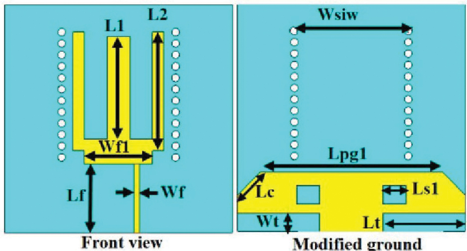
Figure 1: The proposed W-shape vias antenna.
A parametric study in terms of the reflection coefficient is performed on the proposed antenna with and without vias besides T-shape modified ground with respect to the diameter of vias as in Fig. 2 (a). Figure 2 shows the reflection coefficient responses with different values of vias diameter. It has been found that the optimal case for a wideband reflection coefficient is when the length of slot, width of slot, and vias diameter values are 17 mm, 3 mm, and 4 mm respectively. Hence, the antenna dimensions (in mm) are
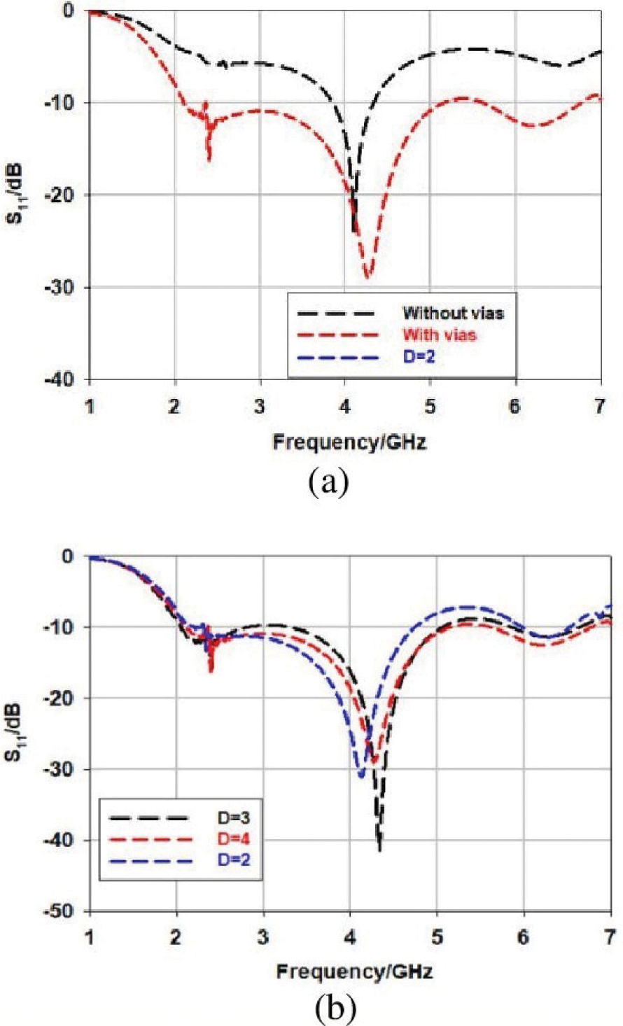
Figure 2: (a) Reflection coefficient with and without vias, (b) Reflection coefficient at several vias dimeter values.
2.2 Metasurface design and integration with antenna
Metasurface is characterized by its resonant frequency (f). The resonant frequency is calculated with the considerations of the capacitance (C)and inductance (L) properties of the transmission line. By altering the values of capacitance and inductance, the frequency is shifted to the higher or lower frequency or toward desired frequency. The resonant frequency can be found by [14]:
| (4) |
Therefore, the elements’ conductivity are filtered using a lattice etched on a dielectric substrate. This forms a full metasurface consisting of multiple unit cells. This also allows the metasurface to pass or reject certain signal at specific frequency. Therefore, a metasurface is implemented using square split ring resonator (SSRR) to increase the gain of the antenna. Similarly, the metasurface is fabricated by low-cost FR4 substrate with same height and permittivity as antenna. The unit cell is designed with four SSRR cells as shown in Fig. 3. The frequency of the four SSRR is found by [14]:
| (5) |
Where, the length of unit cell is (L), the width of the cell is (WW), the gap between each cell is (S), the cut in each SSR is (g), and the width of last resonator is (SS). The capacitance and the inductance can be obtained as [14]:
| (6) |
| (7) |
| (8) |
Hence, the values of the unit cell is as follows:
SS = 1 mm.
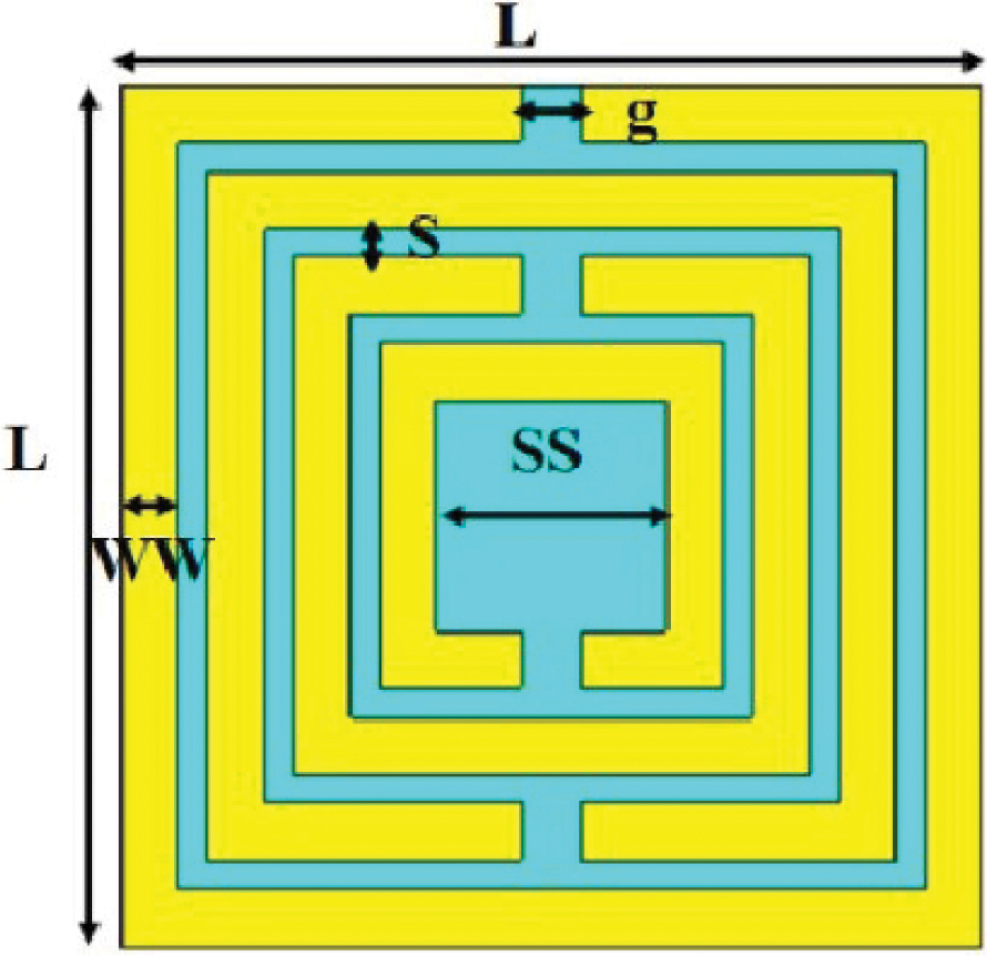
Figure 3: SSRR unit cell design.
Figure 4 shows the performance of the SSRR unit cell in terms of S-parameters, permittivity (), and permeability (). The reflection coefficient (S) is shifted below 3.5 GHz as one SSRR is added to the shape as shown in Fig. 4 (a). The transmission coefficient is lagged the reflection coefficient in lower frequency when it compares with higher frequency more than 3.5 GHz as shown in Fig. 1 (b). The method used to extract the metamaterial properties is based on detecting the discontinuity points. This method is simple and works effectively by extracting the discontinuity points from the real part of the refractive index. The permittivity is negative from the range of 3 GHz to 4 GHz as the permeability is positive at sub-6 GHz. Hence, the proposed unit cell behaves as an epsilon-negative metamaterial (ENG) as seen in Fig. 4 (c) and Fig. 4 (d) respectively.
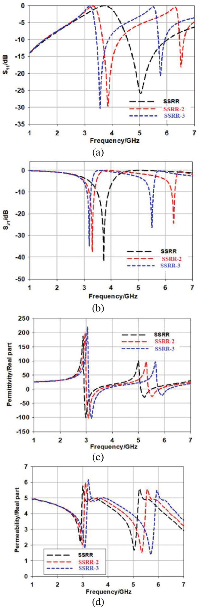
Figure 4: The performance of the SSRR unit cell. (a) Reflection coefficient. (b) Transmission. (c) Permittivity. (d) Permeability.
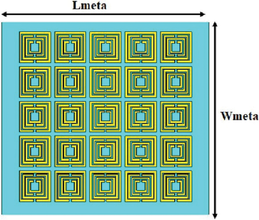
Figure 5: The proposed 5 5 metasurface configuration.
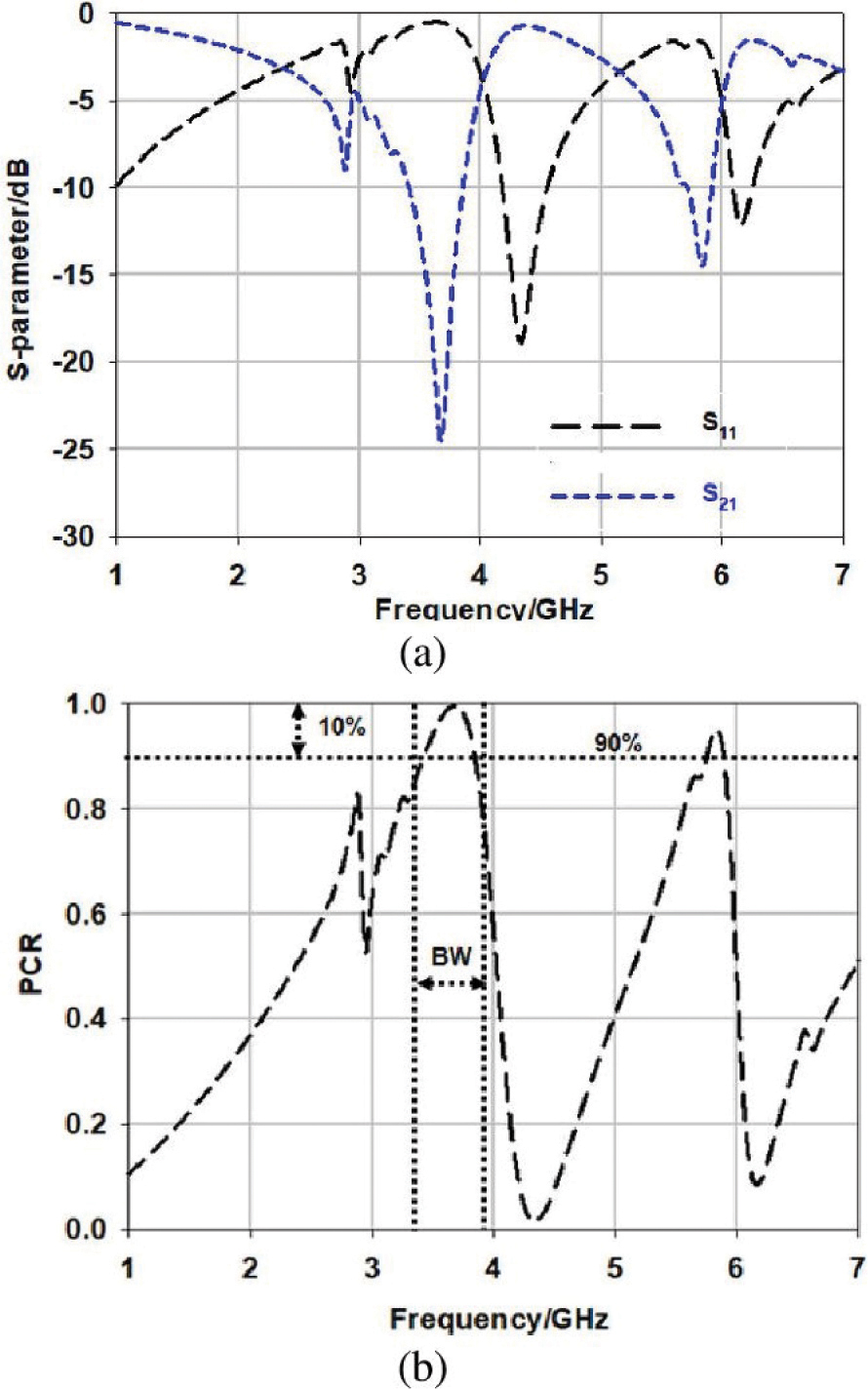
Figure 6: Simulated response of 5 5 metasurface (a) reflection and transmission coefficients. (b) PCR.
As a result, the SSRR unit cell is integrated to form a 5 5 metasurface structure as seen in Fig. 5. The proposed metasurface is symmetric, which gives the same cross-polarization and co-polarization under the normal x-polarized EM wave. The co-polarization at a range of 4.2 GHz to 4.45 GHz is less than 10 dB. At a frequency range above 6 GHz, the co-polarization remains less than 10 dB as seen in Fig. 6 (a). The cross-polarization value is within dB in the range of mid-band (at 3.5 GHz). At 3.5 GHz and 5.8 GHz, the PCR achieved a value higher than 90% as seen in Fig. 6 (b). Therefore, the metasurface validates the increasing of current surface toward increases the gain. The proposed 5 5 metasurface is placed above a proposed antenna to validate the high gain property as presented in Fig. 7. The proposed structure consists of antenna layer at bottom and metasurface layer with unit cells are faced the antenna from above with a separation distance (air) between the layers (d). Figure 8 presents the comparison of simulated results in terms of the reflection coefficient, gain, axial ratio, and radiation pattern of the antenna with respect to metasurface at d= 15 mm. At 3.5 GHz, it has been found that the reflection coefficient is 23.5 dB with fractional bandwidth of 3 GHz for both antenna and metasurface antenna as in Fig. 8 (a). The gain is increased to 7.33 dBi when the SSRR metasurface is applied compared to the gain of antenna of 2.33 dBi as in Fig. 8 (b). Both axial ratios in the two cases sill same over the bandwidth with less than 3 dB as in Fig. 8 (c). Circularly polarized radiation pattern of 2.3 dB can be seen without metasurface applied compared to directive radiation pattern of 8 dB when metasurface is applied as shown in Fig. 8 (d). As a result, the simulated performance of the antenna with metasurface showed a great impedance bandwidth, high gain, and wide axial ratio.
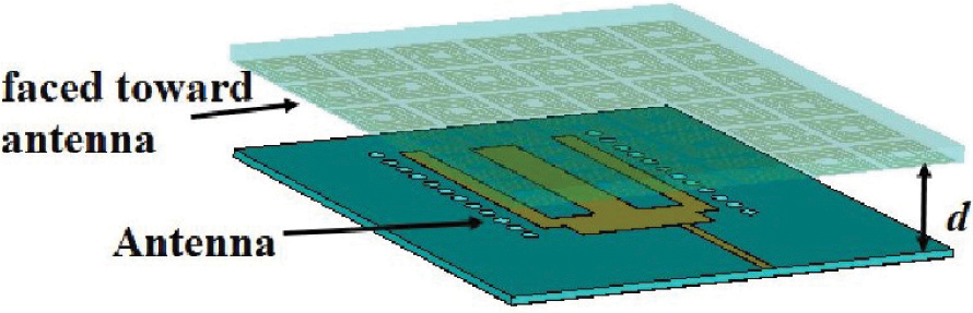
Figure 7: The proposed metasurface placed above the antenna.
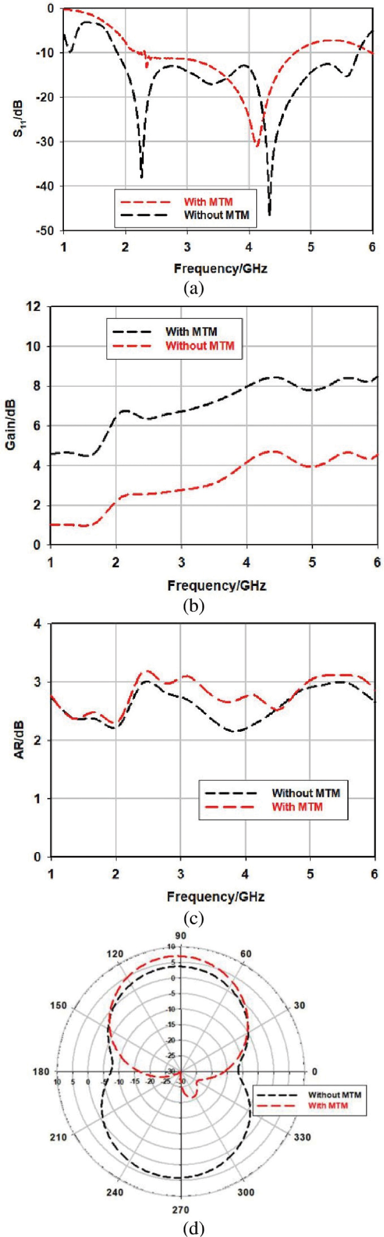
Figure 8: Comparison of proposed antenna with and without Metasurface. (a) Return loss. (b) Gain. (c) Axial ratio. (d) Radiation pattern.
3 RESULTS AND DISCUSSION
Figure 9 shows the printed antenna with metasurface with total dimensions of 50 mm 50 mm that highlighted the compact size of the whole system. The measured results in terms of S-parameters are performed using Keysight (Agilent Technologies) N9925A vector network analyser (VNA). The performance of printed antenna with metasurface in terms of reflection coefficient, radiation pattern, gain, and AR are compared with simulated results in Fig. 10.
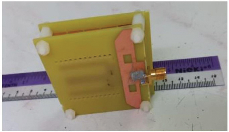
Figure 9: The printed metasurface with antenna.
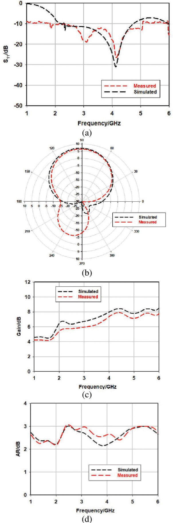
Figure 10: The measured performance of the printed fractal antenna. (a) Reflection coefficient. (b) Radiation pattern. (c) Gain. (d) AR.
The measured performance of the reflection coefficient is plotted in Fig. 10 (a). The measured (S) is 23.58 dB compared to the simulated one of 30.2 dB at 4 GHz. The measured fractional bandwidth is 2.99 GHz with a loss of 100 MHz of simulated bandwidth (3 GHz). The measured radiation pattern agreed well with the simulated one with an error tilt of 3 degrees as seen in Fig. 10 (b). Figure 10 (c) shows the measured gain response compared to the simulated one. The measured gain is 7.2 dBi with 0.8 dBi loss compared to the simulated 8 dBi gain. This is due to the interference coming from the unwanted sources from the radiation pattern chamber. The AR performance is compared in Fig. 10. Over the operating frequencies, the AR value is above 82%. For example, at 4 GHz the measured and simulated AR has a small gap of 0.5 dB difference. Table 1 summarizes the antenna with metasurface performance and compares it with other related works. Overall, the printed antenna with metasurface exploited a great performance in terms of bandwidth, AR, and gain.
Table 1: Comparison between measured and simulated antenna with metasurface at 4 GHz with related existing works
| Parameters/Coupler | Simulated | Measured |
| Return loss (S) (dB) | 30.2 | 23.58 |
| Bandwidth (GHz) | 3 | 2.90 |
| Gain (dBi) | 8 | 7.2 |
| AR (dB) | 2.2 | 2.5 |
| Comparison with related works | ||||
| Ref | Gain | BW (GHz) | Size% | AR (BW) |
| [9] | 2.56 | 2.19 GH | 50% | 3.39 GHz |
| dBi | 3.7 GHz | 3.55 GHz | ||
| [10] | 3.2 | 2.43 GHz | 65% | 2.43 GHz |
| dBi | 2.47 GHz | 2.47 GHz | ||
| [11] | 2.5 | 12.2 GHz | 12.2 GHz | |
| dBi | 12.7 GHz | 12.7 GHz | ||
| [12] | 1.89 | 1.57 GHz | 20% | 1.57 GHz |
| dBi | 1.62 GHz | 1.62 GHz | ||
| This | 7.12 | 2 GHz | 45.2% | 2.5 GHz |
| work | dBi | 5 GHz | 5 GHz |
4 CONCLUSION
A designed compact high gain wideband with a metasurface antenna is presented in this paper at the sub-6 GHz band. The antenna is designed based on a W-shaped transmission line within the structure. The performance of the proposed metasurface antenna agreed well with the simulated results. Excellent S-parameters, bandwidth, gain, and AR performance at 4 GHz are achieved for the designed antenna. The antenna operates in the frequency band of 2 GHz to 5 GHz with a high fractional bandwidth of 85%. The antenna achieved a good profile of compact size by 45%. The proposed antenna is suitable to be used later in sub-6 GHz applications.
REFERENCES
[1] Y. He, S. Lv, L. Zhao, G.-L. Huang, X. Chen, and W. Lin, “A compact dual-band and dual-polarized millimeter-wave beam scanning antenna array for 5G mobile terminals,” IEEE Access, vol. 9, pp. 109042-109052, 2021.
[2] I. Syrytsin, S. Zhang, G. F. Pedersen, and A. S. Morris, “Compact quad-mode planar phased array with wideband for 5G mobile terminals,” IEEE Transactions on Antennas and Propagation, vol. 66, no. 9, pp. 4648-4657, 2018.
[3] N. O. Parchin, J. Zhang, R. A. Abd-Alhameed, G. F. Pedersen, and S. Zhang, “A planar dual-polarized phased array with broad bandwidth and quasi-end fire radiation for 5G mobile handsets,” IEEE Transactions on Antennas and Propagation, vol. 69, no. 10, pp. 6410-6419, 2021.
[4] Y. Kumar and S. Singh, “Microstrip fed multiband hybrid fractal antenna for wireless applications,” Applied Computational Electromagnetics Society (ACES) Journal, vol. 31, no. 3, pp. 327-332, 2016.
[5] M. I. Sabran, S. K. A. Rahim, P. J. Soh, C. Y. Leow, and G. A. E. Vandenbosch, “A simple electromagnetically fed circularly-polarized circular microstrip antenna,” Applied Computational Electromagnetics Society (ACES) Journal, vol. 30, no. 11, pp. 1180-1187, 2015.
[6] M. Majidzadeh, J. Nourinia, and C. Ghobadi, “Compact CPW-Fed antenna with circular polarization characteristics in WLAN frequency band,” Applied Computational Electromagnetics Society (ACES) Journal, vol. 28, no. 10, 2013.
[7] Y. Liu, X. Liang, X. Zhang, J. Li, J. Geng, R. Jin, and L. Zhang, “A K-band broadband circularly polarized slot antenna based on L-shaped waveguide cavity,” IEEE Antennas and Wireless Propagation Letters, vol. 20, no. 9, pp. 1606-1610, 2021.
[8] Z. Zhou, Z. Wei, Z. Tang, and Y. Yin, “Design and analysis of a wideband multiple-microstrip dipole antenna with high isolation,” IEEE Antennas and Wireless Propagation Letters, vol. 18, no. 4, pp. 722-726, 2019.
[9] X. Shuai and S. Xiao, “A novel dual-band circularly polarized slot antenna with fractal slot geometry,” Microwave and Optical Technology Letters, vol. 59, no. 2, pp. 451-456, 2017.
[10] S. Maity, K. R. Barman, and S. Bhattacharjee, “Silicon-based technology: Circularly polarized microstrip patch antenna at ISM band with miniature structure using fractal geometry for biomedical application,” Microwave and Optical Technology Letters, vol. 60, no. 1, pp. 93-101, 2018.
[11] K. S. Kola, A. Chatterjee, and D. G. Patanvariya, “Design of a wideband right-handed circularly polarized array of miniaturized mushroom-shaped antennas for direct broadcast satellite application,” Microwave and Optical Technology Letters, vol. 62, no. 11, pp. 3542-3555, 2020.
[12] E. Wang, M. Liu, D. Lin, and J. Wang, “A compact circular polarized patch fractal antenna for global navigation satellite systems,” Microwave and Optical Technology Letters, vol. 64, no. 3, pp. 520-524, 2022.
[13] Z. Zhang, Y. Fan, and Y. Zhang, “Multilayer half-mode substrate integrated waveguide wideband coupler with high selectivity,” Applied Computational Electromagnetics Society (ACES) Journal, vol. 34, no. 9, pp. 1418-1425, 2019.
[14] H. A. Atallah, A. B. Abdel-rahman, K. Yoshitomi, and R. K. Pokharel, “Mutual coupling reduction in MIMO patch antenna array using complementary split ring resonators defected ground structure,” Applied Computational Electromagnetics Society (ACES) Journal, vol. 31, no. 7, pp. 737-743, 2016.
BIOGRAPHIES

Ahmed A. Abbas has been the head of the Electrical Engineering Department, College of Engineering, and the University of Anbar since 2018. He received a B.Sc. degree in Electrical Engineering from the University of Technology in 1994, an MS.c. in Communication Engineering from the University of Technology in 2005 and his Ph.D. in Communication Engineering from Ankara Yldrm Beyazt University in 2017. Dr. Ahmed is a researcher in the field of communications, particularlyin optical wave propagation through random media.

Balasem Salem Samet is a lecturer at the Electrical Engineering Department, College of Engineering, University of Anbar. He received a B.Sc. degree in Electrical Engineering from the University of Technology in 2000, received an MS.c. in Communication Engineering (University of Technology) in 2005, and received Ph.D. in Communication Engineering in 2013. Dr. Balasem is a researcher in wireless communication and smart antennas.
ACES JOURNAL, Vol. 37, No. 8, 886–892.
doi: 10.13052/2022.ACES.J.370807
© 2022 River Publishers