Determination of the Physical Integrity of Ethernet Cables by Obtaining their Transmission Line Parameters from Measured Impedance Profiles
Olusegun Ogundapo and Alistair P. Duffy
1School of Engineering, American University of Nigeria, PMB 2250, Yola-Nigeria
olusegun.ogundapo@aun.edu.ng, segundapo@gmail.com
2School of Engineering and Sustainable Development, De Montfort University, LE1 9BH, United Kingdom
apd@dmu.ac.uk
Submitted On: May 23, 2022; Accepted On: November 7, 2022
ABSTRACT
A method of determining the physical integrity of Ethernet cables by obtaining their transmission line parameters (resistance, inductance, capacitance, and conductance) from their measured impedance profiles are presented. The transmission line parameters were extracted across the cable lengths rather than frequencies used in most research. The method can be used to examine the physical integrity of Ethernet cables before their deployment. The study of the physical integrity of Ethernet cables is very important because, in typical installations, cables can be manipulated in the form of repeated coiling and uncoiling. The installation handling stress can adversely affect the signal integrity especially if they are substandard Ethernet cables. In this paper, four Ethernet cables were subjected to three coiling and uncoiling tests to represent installation handling stress. The impedance profiles of the four cables across their lengths were measured for the three handling stress test conducted. The computation of the transmission line parameters of the Ethernet cables using measured impedance profiles was implemented with the aid of Matrix Laboratory (MATLAB). The outcome of the research showed that the method presented will be very useful to cable installers and contractors in making objective decisions in the choice of cables for deployment.
Index Terms: Ethernet cables, impedance profile, physical integrity, transmission line parameters.
I. INTRODUCTION
Ethernet over twisted pair cables has over the years provided a cost-effective solution for network connectivity as it offers low cost, ease of use, and scalability [1–3]. The use of Ethernet over twisted pair cables can now be found in Internet of things (IoT), industrial and automotive applications [4, 5]. The trend for future Ethernet over twisted pair cables is now towards higher bandwidths on shorter cable lengths [6, 7].
It has been observed that the way twisted pair cables are packaged and handled during installation could undermine their physical structure especially if they are non-standard compliant and counterfeit [8, 9]. There are also the problems of non-compliant cables due to poor quality control [10]. The availability of copper-clad aluminum cables (CCA) in the market that have been termed unfit for use as communication cables is another problem of great concern to cable engineers and installers [11, 12].
There is, therefore, the need for cable engineers to examine the physical integrity of selected cables in the market before their deployment to ensure that signal degradation will be minimized after installation. Most of the research in the literature is focused on computing the transmission line parameters across their frequencies [13–15]. This paper provides a method of examining the physical integrity of the Ethernet cables by obtaining the resistance, inductance, capacitance, and conductance (RLCG) across their lengths from measured impedance profiles using MATLAB. The method presented also enables cable engineers to have a view of where the length of the cable is adversely affected. Four twisted pair cables including a CCA cable were subjected to three times-coiling and stretching tests to study their physical integrity.
II. MATERIALS AND METHODS
A. Cable materials
The cable materials used for the computation of RLCG parameters from the measured impedance profiles are:
• Cable 1: insulating material is polyethylene, conductor material is copper, the diameter of the conductors is 0.57 mm, and the distance between the centers of the conductors is 0.99 mm.
• CCA cable 2: insulating material is polyethylene, conductor material is copper, cladding material is copper, diameter of the conductors is 0.57 mm, and the distance between the centers of the conductors is 1.03 mm.
• Cable 3: insulating material is polyethylene, conductor material is copper, diameter of the conductors is 0.54 mm, and the distance between the centers of the conductors is 0.96 mm.
• Cable 4: insulating material is polyethylene, conductor material is copper, diameter of the conductors is 0.57 mm, and the distance between the centers of the conductors is 1.01 mm.
B. Methodology
The RLCG parameters per unit-length for a single pair of cables will be computed from their measured impedance by using the mathematical expression for the transmission line parameters.
The R, L, G, and C can be calculated as expressed in [16] as follows:
The resistance (R) per meter is:
| (1) |
where the surface resistivity is:
| (2) |
The inductance per meter is:
| (3) |
The conductance per meter is:
| (4) |
The capacitance per meter is:
| (5) |
where D is the distance between the centers of the conductors, d is the diameter of the conductor, is the permeability of the conductor, is the conductivity of the conductor, is the conductivity of the insulating material, is the effective permittivity of the insulating material, is the permeability of the insulating material and f is the frequency in Hz.
The attenuation constant (), which is the real part of the propagation constant (), is expressed in [17] as:
| (6) |
Similarly, the phase constant (), which is the imaginary part of the propagation constant (), is given in [17] as:
| (7) |
Therefore, the propagation constant () from equations (6) and (7) is:
| (8) |
The RLCG parameters for a single pair of the cable can now be computed from the cable impedance given in [15, 18] as:
| (9) |
| (10) |
| (11) |
| (12) |
where is the twisted pair cable impedance measurements in ohms due to handling stress test.
C. Measurement procedure
Four category 6 unshielded twisted pair (UTP) cables were selected for the impedance profile measurements. The cables selected are tagged Cable 1, Cable 2 (CCA), Cable 3, and Cable 4. The DSX-5000 cable analyzer that can handle testing and certification of category 6 cables was used for the impedance measurement [19, 20]. The UTP cables were tested in accordance with the International Standard ISO/IEC 11801 Class E, which can measure up to 250 MHz. The cable analyzer contains two main modes: “main” and the “remote”, which have openings to connect them to standard link adapters [20]. These main and remote modes are connected through patch cord plugs to the cable under examination [20]. The DSX-5000 analyzer has a High-Definition Time Domain Reflectometry (HDTDR) embedded in it to measure the impedance profiles across the length of the cables. The schematic diagram of the cable analyzer set up for measurement is shown in Fig. 1.
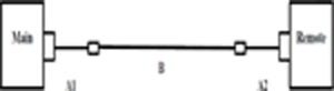
Figure 1: The schematic diagram of the cable analyzer measurement setup. Note: A1 is the main mode link interface adapter with the patch cord plug, A2 is the remote link interface adapter with the patch cord plug, andB is the UTP cable under test.
Our research used the standard T568 pin connection with the registered (RJ45) connector for the four pairs of each cable to be measured. The four cables under the impedance profiles test consist of four twisted pairs each of which was labeled as orange, blue, green, and brown.
The coiling of the cables had a diameter of 30 cm so as to exceed the maximum bending allowed. The three test measurements taken are as follows:
• Measurement 1: cable used to form coils and stretched before test
• Measurement 2: cable in measurement 1 used to form coils and stretched before test
• Measurement 3: cable in measurement 2 used to form coils and stretched before test
III. MEASURED IMPEDANCE PROFILES
The measured impedance profiles across the lengths of the four cables at 250 MHz using the third coiling and uncoiling test results is shown in Figs. 2–4 for the orange, green and blue pairs. A view of Figs. 2–4 show that the CCA cable 2 is the most affected by the installation handling test as it gave a distinct variation in impedance profiles for all pairs.
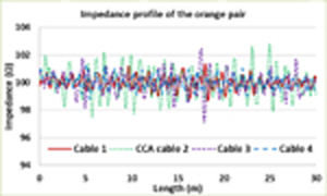
Figure 2: Impedance profile of the orange pair.
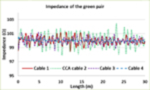
Figure 3: Impedance profile of the green pair.
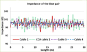
Figure 4: Impedance profile of the blue pair.
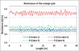
Figure 5: Resistance comparison of the four cables using the orange pair.
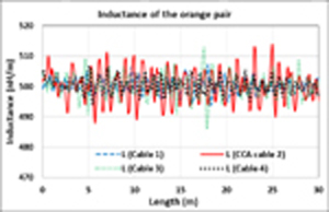
Figure 6: Inductance comparison of the four cables using the orange pair.
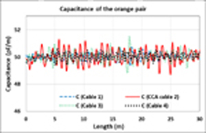
Figure 7: Capacitance comparison of the four cables using the orange pair.
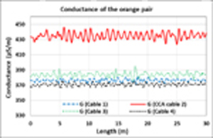
Figure 8: Conductance comparison of the four cables using the orange pair.
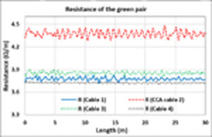
Figure 9: Resistance comparison of the four cables using the green pair.
IV. RESULT OF THE RLCG PARAMETERS EXTRACTED FROM MEASUREMENT
The results of the RLCG parameters across the lengths of the four cables at 250 MHz using the third coiling and uncoiling measured impedance results are shown from Figs. 5–16 for the orange, green, and blue pairs. Figures 5–16 show that CCA Cable 2 had a wide margin for resistance and conductance in comparison to the other three cables, indicating that it is the most affected by the installation handling test.
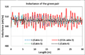
Figure 10: Inductance comparison of the four cables using the green pair.
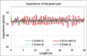
Figure 11: Capacitance comparison of the four cables using the green pair.

Figure 12: Conductance comparison of the four cables using the green pair.
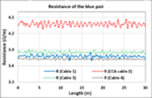
Figure 13: Resistance comparison of the four cables using the blue pair.
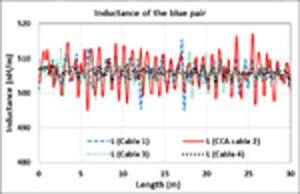
Figure 14: Inductance comparison of the four cables using the blue pair.

Figure 15: Capacitance comparison of the four cables using the blue pair.

Figure 16: Conductance comparison of the four cables using the blue pair.
V. DISCUSSION OF THE RESILIENCE OF THE CABLES
The graphical results in Figs. 5–16 show that the CCA cable 2 gave a distinct wide margin in the resistance and conductance across the length than the three other cables for all pairs. This indicates that the CCA cable 2 gave the worst resilience after the third handling stress test than the three other cables. This confirms what is stated in literature that it is a bad communication cable. On the other hand, a view of the plots in Figs. 5–16 show that cable 4 gave the least changes in the RLCG parameters in comparison to the other three cables. This indicates that cable 4 gave the best resilience after the third test. The results of the test show that cable 4 has the best physical integrity as it is the least affected by the coiling and uncoiling tests.
VI. CONCLUSIONS
This paper has provided a method that can be used to determine the physical integrity of Ethernet cables by obtaining the RLCG parameters from their measured impedance profiles using MATLAB. The research was the determination of the transmission line parameters across their lengths to have a better view of the cable behavior. Four Ethernet cables were examined including a CCA cable termed unfit for use as a communication cable. The results of the study indicate that the CCA cable provided the worst resilience to the handling stress tests as it showed the highest changes in the RLCG parameters across the length. Cable 4 on the other hand, gave the best resilience to the handling stress tests as it showed the least changes in the RLGC parameters across the length. The method provided will be of help to cable engineers, installers, and contractors when selecting cables for deployment to minimize problems that may arise after installation.
REFERENCES
[1] A. Oliviero, Cabling Part 1: LAN/Data Center Networks and Cabling Systems, 5th Edition. John Wiley and Sons Inc., 2014.
[2] A. Semenov, “Design requirements to tel-telecommunications long ethernet twisted pair cable,” XIV International Scientific-Technical Conference on Actual Problems of Electronics Instrument Engineering (APEIE), Khartoum, pp. 27-31, Oct. 2018.
[3] C. Spurgeon and J. Zimmerman, Ethernet: The Definitive Guide, Second Edition, O’Reilly Media, Inc, 2014.
[4] R. Elton, E. Hamood, A. Mohammed, and A. Osman, “Early warning firefighting system using the internet of things,” International Conference on Computer, Control, Electrical and Electronic Engineering (ICCCEEE), Khartoum, pp. 111-118, Aug. 2018.
[5] A. Gercikow, S. Schaffenroth, H. Schmidt, and A. Kolpin, “Measurement platform for physical-layer analysis of industrial and automotive ethernet,” IEEE Sensors Applications Symposium (SAS), Kuala Lumpur, pp. 122-128, Mar. 2020.
[6] P. McLaughlin, “The past, present and future of cabling technologies, products and standards,” Cabling Installation and Maintenance Magazine, vol. 24, no. 12, pp. 27-29, Dec. 2018.
[7] O. Ogundapo, C. Nche, “Modeling the insertion loss of structured ethernet cabling standard using the scattering parameters,” Applied Computational Electromagnetics Society (ACES) Journal, vol. 37, no. 4, pp. 435-440, Apr. 2022.
[8] B. Shuman, “Is your Ethernet cable tough enough,” Cabling Installation and Maintenance Magazine, vol. 13, no. 9, pp. 25-27, Sep. 2003.
[9] P. McLaughlin, “Counterfeit cable is getting ugly,” Cabling Installation and Maintenance Magazine, vol. 19, no. 8, pp. 31-32, Aug. 2011.
[10] Beyondtech, “The three major counterfeit communications cabling scams,” Cabling Installation and Maintenance Magazine, vol. 21, no. 5, pp. 28-30, May 2017.
[11] P. McLaughlin, “Copper clad aluminum conductors, the latest counterfeiting ploy,” Cabling Installation and Maintenance Magazine, vol. 19, no. 4, pp. 24-26, Apr. 2011.
[12] FLUKE Networks, Copper Clad Aluminum Cables (CCA). 2019. Available online: https://www.flukenetworks.com/content/application-note-copper-clad-aluminum-cables accessed on Apr. 16, 2022.
[13] M. Yamamura, Y. Kami, K. Murano, and F. Xiao, “Analysis of transmission line characteristics for twisted pair cables using the RLGC parameters of the cable,” Asia-Pacific Symposium on Electromagnetic Compatibility (APEMC), Taiwan, pp. 720-723, May 2015.
[14] C. Afifah, C. Alam, F. Seman, A. Asrokin, and N. Nohan, “Impact of cable bleeding into RLGC of twisted pair copper cable and achievable rate,” 7th International Conference on Computer and Communication Engineering (ICCCE), Malaysia, pp. 321-326, Sep. 2018.
[15] M. Degerstrom, B. Gilbert, and E. Daniel, “Accurate resistance, inductance, capacitance and capacitance (RLCG) from uniform transmission line measurements,” IEEE-EPEP Electrical Performance ofElectronic Packaging Conference, San Jose, pp. 77-80, Oct. 2008.
[16] F. Ulaby, E. Michielssen, and U. Ravaioli, Fundamentals of Applied Electromagnetics, 6th Edition, Prentice Hall, 2010.
[17] D. Pozar, Microwave Engineering, Fourth Edition, John Wiley and Sons Inc., 2012.
[18] M. Sampath, “On Addressing the practical issues in the extraction of RLGC parameters for lossy multiconductor transmission lines using S-parameters models,” IEEE-EPEP Electrical Package, San Jose, pp. 259-262, Oct. 2008.
[19] FLUKE Networks, “Datasheet: DSX-5000 cable analyzer.” 2019. Available online: https://www.flukenetworks.com/content/datasheet-dsx-5000-cableanalyzer accessed on April 15, 2022.
[20] FLUKE Networks, “Versiv Cabling Certification Product Family User’s Manual, Versiv Software Version 4.8.” 2016. Available online: https://www.testequipmentdepot.com/fluke-networks/pdf/versiv_manual.pdf accessed on April 15, 2022.
BIOGRAPHIES
Olusegun E. Ogundapo received a Ph.D. degree in Electronic Engineering from De Montfort University, United Kingdom. He also has an M.Sc. degree in Electrical Engineering from Ahmadu Bello University, Zaria, and a B.Eng. in Electrical and Electronic Engineering from the Federal University of Technology, Yola (now Modibbo Adama University), Yola-Nigeria. He is now an Assistant Professor at the School of Engineering, American University of Nigeria, Yola-Nigeria. His research interests are in computational electromagnetics, validation, data analysis, signal integrity, wireless/wired communication media analysis, and modeling.

Alistair P. Duffy received the B.Eng. (Hons.) degree in Electrical and Electronic Engineering and the M.Eng. degree from the University College, Cardiff, U.K., in 1988 and 1989, respectively. He received his Ph.D. degree from Nottingham University, Nottingham, U.K., in 1993 for his work on experimental validation of numerical modeling. He was awarded a D.Sc. in 2019 from Cardiff University for his work on the validation of computational electromagnetics. He is currently Director of the Institute of Engineering Sciences and Professor of Electromagnetics at De Montfort University, Leicester, U.K. He is also a Guest Professor at Harbin Institute of Technology, Harbin, China, a visiting professor at Xi’an Jiaotong University, China, and a 2022 Visiting professor at EPFL, Switzerland. He is the author of approximately 300 articles published in journals and presented at international symposia. His research interests include CEM validation, communications cabling, and technology management.
Dr. Duffy is a Fellow of the IEEE, the Institution of Engineering and Technology (IET), and the Royal Society for the Encouragement of Arts, Manufactures and Commerce (RSA). He is the Immediate Past President of the IEEE EMC Society and Director-Elect of the IEEE. He is an Associate Editor of the IEEE Transactions on EMC and of the IEEE Letters on EMC Practice and Application. He was the General Chair of the IEEE Symposium on EMC + SIPI in 2020 and the joint symposium with EMC Europe in 2021.
ACES JOURNAL, Vol. 37, No. 10, 1051–1057
doi: 10.13052/2022.ACES.J.371005
© 2022 River Publishers