Sectional Modular Technology for Reducing Detent Force of Linear Unit in Linear-rotary Flux-switching Permanent-magnet Generator for Wind-wave Combined Energy Conversion
Guozhen Zhang, Rui Nie, Jikai Si, Xiaohui Feng, and Changli Wang
1School of Electrical and Information Engineering
Zhengzhou University, Zhengzhou, 450001, China
zhanggz18312@126.com, nierui@zzu.edu.cn, sijikai527@126.com
2School of Mechanical and Electrical Engineering
North China Institute of Science and Technology, Beijing, 101601, China
fengxh@ncist.edu.cn
3School of Computer Science
North China Institute of Science and Technology, Beijing, 065201, China
wangcl@ncist.edu.cn
Submitted On: May 27, 2022; Accepted On: April 18, 2023
ABSTRACT
A linear-rotary flux-switching permanent magnet (FSPM) generator (LRFSPMG) is a potential candidate for a wind-wave combined energy conversion (WWCEC) system. The linear unit of the LRFSPMG is a tubular FSPM linear generator (TFSPMLG), which like other permanent magnet linear generators, has an inherent detent force problem. To alleviate this problem, a sectional modular technology scheme is investigated to reduce the detent force of the TFSPMLG. Firstly, the structure is briefly introduced and the detent force analyzed. Secondly, the sectional modular TFSPMLGs are presented and their feasibility verified with respect to the stator of the TFSPMLG being split into two and three sections, forming Modulars I and II, respectively. After that, the detent force suppression principle, and the effects that the sectional modular structures exert on the detent force are analyzed. According to the analysis results, two methods are presented to suppress the detent force: one is to suppress the magnetic coupling effect; the other is to reduce the remaining harmonics. Finally, the three TFSPMLGs, including the initial TFSPMLG, Modular I, and Modular II, are comparatively analyzed by finite-element analysis (FEA). The results show that both the detent forces are greatly reduced without sacrificing the back electromotive force (EMF) and average electromagnetic force, thereby proving the effectiveness of the TFSPMLG with a sectional modular structure.
Index Terms: detent force, flux-switching, sectional modular technology, tubular permanent-magnet linear generator.
I. INTRODUCTION
Wind energy and wave energy are significant sources of renewable energy and have attracted considerable attention owing to the advantages of high energy density, environmental protection, and wide distribution with large reserves [1, 2]. More recently, wind-wave combined energy conversion (WWCEC) systems employing a linear-rotary generator have emerged and developed rapidly since they can harvest both these energy sources to generate electrical energy simultaneously through a single generator, thus improving the efficiency and economy of such systems [3].
As one of the core components of WWCEC systems, linear-rotary generators are expected to provide high power and efficiency with high operational reliability in harsh offshore environments [4]. Since flux-switching permanent magnet (FSPM) generators inherit the merits of conventional permanent magnet (PM) generators (high power) and switched reluctance generators (robust structure) [5], the FSPM generator is considered to be a promising candidate for WWCEC systems. Accordingly, a linear-rotary FSPM generator, comprising linear and rotary units, is proposed for WWCEC systems [6, 7]. However, the linear unit, which is a tubular FSPM linear generator, suffers from the detent force caused by slot effect and end effect, thereby leading to the deterioration of the electrical generation capability. Hence, reducing the detent force is a key aim in order to improve the performance of the TFSPMLG.
Existing methods indicate that the problem of detent force can be largely resolved by reducing the cogging force, e.g., by skewing the pole or slot, asymmetrical distribution of stator teeth [8, 9], optimizing the tooth pitch, or optimizing the shape of PMs [10, 11]. However, these methods are unsuited to a TFSPMLG since the end force has a greater impact on the FSPM machine [12]. Another approach involves suppressing the end effect by methods such as adding assistant teeth or auxiliary poles, adjusting the width and length of end teeth, and optimizing the slot structure [13, 14]. These measures can improve the flux distribution around the ends to suppress the end effect, thus effectively reducing the detent force. Meanwhile, compensation windings are also widely employed to reduce the detent force by injecting proper current into compensation coils and combining control strategy [15, 16]. However, this measure generally needs to be combined with other measures to achievebetter results.
Recently, a modular technology scheme was put forward and implemented in various machines to reduce the detent force [17–21]. In [17], each slot of the machine was dispersed, and the detent force was greatly reduced by the mutual influence between the single primary units. In [18, 19], the primary iron was divided into two sections to form a modular structure. In that situation, the fundamental and odd-order harmonics components in the detent force can be eliminated. At the same time, the primary component with a three-section structure was also adopted, in which only the third and its multiple harmonics remained in detent force, and other harmonics components were offset [20, 21]. Moreover, this method does not add to the manufacturing complexity. The above modular technology scheme therefore suggests a new approach to reducing detent force, and in terms of the existing research findings, can achieve better results in PM linear machines. As a type of linear machine, whether the modular technology scheme works for a TFSPMLG needs further investigation.
Accordingly, this paper presents a sectional modular TFSPMLG approach to reducing detent force. The paper is organized as follows. In Section II, the structure of the TFSPMLG is briefly introduced and the detent force is analyzed. Then, the sectional modular TFSPMLG is presented in terms of its feasibility, the principle of detent force suppression, and analysis of the effects that the sectional modular structures exert on the detent force. In Section III, detent force minimization methods are conducted based on the analysis results. The three TFSPMLGs, including the initial TFSPMLG, Modular I, and Modular II, are analyzed comparatively by two-dimensional finite-element analysis (2D-FEA) in Section IV. Finally, the conclusions are summarized in Section V.
II. INITIAL AND SECTIONAL MODULAR STRUCTURE OF TFSPMLG AND THE DETENT FORCE
A. Initial structure and detent force of the TFSPMLG
Figure 1 (a) show the structure of the LRFSPMG, which is composed of a linear unit and a rotary unit. Ignoring the influence between the linear unit and rotary unit, the detent force of the LRFSPMG can be regarded as that of the linear unit. In the interest of simplicity analysis, the following research focuses on the linear unit in order to investigate the detent force of the LRFSPMG. It can be observed from Fig. 1 (b) that, for the linear unit, it is a 12s/14p TFSPMLG. Both PMs and armature windings are placed in the stator, and the mover only consists of the iron core. PMs with opposite magnetization are sandwiched between dumbbell-shaped laminated segments, which are wound by toroidal-shaped coils. Since the magnetic circuit is imbalanced due to the end effect existing, the end teeth are adopted at the end sides of the stator. The major parameters of the TFSPMLG are listed in Table 1.
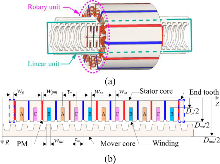
Figure 1: Structure of generator: (a) LRFSPMG; (b) two-dimensional structure of linear unit in RZ coordinatesystem.
The default mover velocity is 1 m/s and the default load is 10 in this simulation. The detent force and electromagnetic force of the TFSPMLG are simulated by 2D-FEA, as shown in Fig. 2. The variation trend of the electromagnetic force is consistent with the detent force. Meanwhile, in a fluctuating period of one mover pole pitch , the fluctuation amplitude of the electromagnetic force is close to that of the detent force, which indicates that the fluctuation of the electromagnetic force is mainly affected by the detent force. Thus, the electromagnetic force ripple can be effectively suppressed by reducing the detent force.
Table 1: Parameter of the TFSPMLG
| Item | Symbol | Value |
|---|---|---|
| Outer diameter of mover | D | 118 mm |
| Outer diameter of stator | D | 73 mm |
| Diameter of stator yoke | D | 25 mm |
| Stator pole pitch | 24 mm | |
| Mover pole pitch | *12/14 | |
| Number of slots | N | 12 |
| Number of poles | N | 14 |
| Width of stator teeth | w | 6 mm |
| Width of slot | w | 6 mm |
| Width of PM | w | 4 mm |
| Width of mover teeth | w | 6 mm |
| Width of end teeth | w | 6 mm |
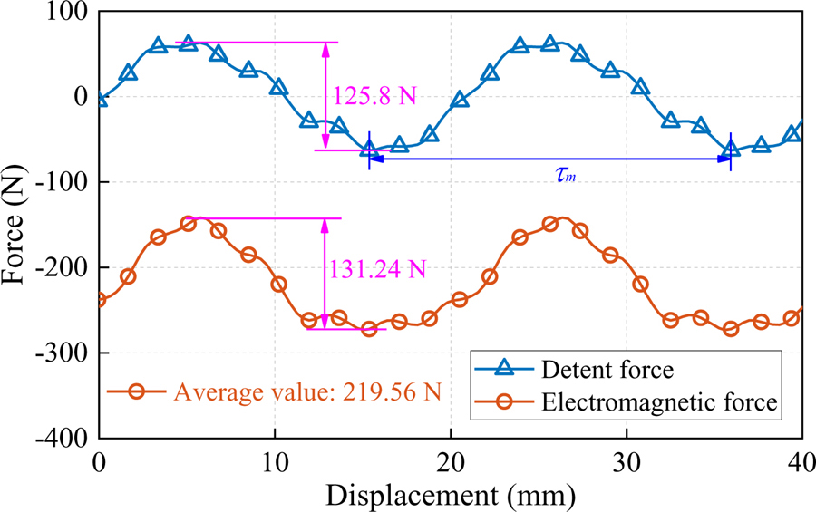
Figure 2: Detent force and electromagnetic force of the TFSPMLG.
B. Sectional modular structure of the TFSPMLG
For the purpose of suppressing the detent force, this paper proposes the adoption of a sectional modular technology structure. If the coils in each section are the same, the stator can be divided into two, three, four, six, and twelve sections. However, too many sections may lead to the waste of the stator volume, which results in reduced force density [20]. Hence, this study only considers the case where two or three sections are selected.
Based on the above description, the TFSPMLG stator can adopt either a two-section structure, three-section structure, or both, in which the stator is split into two sections and three sections, named Modular I and Modular II respectively, as shown in Fig. 3. The flux barrier, which can be made of air or nonmagnetic material, is set between two sectional stators. Each sectional stator in Modular I/II is the same and combines with the mover forming a unit generator. According to the design principle of mutual offset detent force between generator units [22], the TFSPMLG with the two-section and three-section structures needs to satisfy equations (1) and (2), respectively:
| (1) |
| (2) |
where L and L are the length of the sectional stator, L and L are the length of the flux barrier for the Modular I and II, respectively, is the mover pole pitch, and k is a positive integer.
However, irrespective of which structure scheme is selected, the sectional modular TFSPMLG, while meeting the offset of detent force, should also meet the design principle requirements of the complementary structure. To verify the feasibility of the sectional modular technology scheme, the design principle of the sectional modular TFSPML is analyzed with two-section and three-section structures.
For the non-modular FSPM linear machine, the complementary structure of the windings requires satisfying two conditions [23]. Firstly, the relative distance between the two adjacent coils of one phase should satisfy:
| (3) |
Secondly, the displacement between the two coils of the adjacent two phases should satisfy:
| (4) |
Therefore, under the condition that the complementary winding characteristics are met, the spacer coils distance of one phase should satisfy the following relationships:
| (5) |
Meanwhile, if the spacer coils are wound reversely or the magnetization directions of PMs on both sides of them are different, the electrical angle difference between spacer coils of one phase is 180, i.e., the distance difference being /2. Consequently, the preceding analysis indicates that the relative distance between spacer coils of one phase can be expressed as:
| (6) |
where j and m are positive integers.
For the sectional modular TFSPMLG shown in Fig. 3, the lengths of the sectional stator and flux barrier have the following relationship with :
| (7) |
where L and L are the length of the sectional stator and flux barrier, respectively, i is I or II, which indicates Modular I or II, is the stator pole pitch, and n is a positive integer.
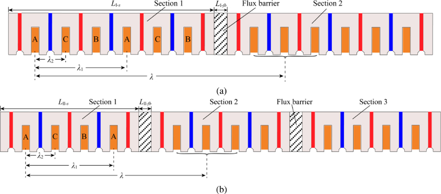
Figure 3: Sectional modular structure of the TFSPMLG: (a) Modular I; (b) Modular II.
Substituting equation (6) into equation (7) and combining with pole pitch ratio / of 14/12, the sum of the sectional stator length and flux barrier length can be expressed as:
| (8) |
Comparing equations (1), (2), and (8), it can be found that (1) and (2) are special forms of (8); i.e., n is 0 and m is 0 (n = 2, 8, 14, …), separately. In other words, while satisfying equations (1) and (2), the complementary structure of the sectional modular TFSPMLG is also satisfied, which verifies the feasibility of the TFSPMLG with two-section and three-section structures. Hence, for sectional modular TFSPMLG, the two-section structure and three-section structure can both be applied. Accordingly, both sectional modular structures are investigated in this paper.
C. Theoretical analysis of detent force of the sectional modular TFSPMLG
For the sectional modular TFSPMLG, the unit detent force of each unit generator can be expressed by Fourier series expansion as follows:
| (9) |
where F and are the amplitude and phase of the nth component respectively, i is I or II, and x is the mover position.
Ignoring the magnetic coupling effect between sectional stators, each unit generator is independent. In that case, the amplitudes of the unit detent force are the same, but their phases are different. Considering the relative distance between the unit generators, the whole detent forces of the sectional modular TFSPMLGs can be expressed as:
| (10) |
| (11) |
where f and f are the whole detent force of Modular I and II, respectively.
According to the design principle of mutual offset detent force in Section II-B, the whole detent force can be calculated as:
| (12) |
| (13) |
According to equations (12) and (13), after setting the sectional modular structure, the fundamental and some higher harmonics in unit detent force can be offset. For Modular I, the whole detent force consists of the remaining second and its multiple harmonics, while the whole detent force is composed of the remaining third and its multiple harmonics for Modular II.
D. Detent force of the sectional modular TFSPMLG
In the initial design, the sectional stator lengths L and L satisfy:
| (14) |
By substituting equation (14) into equations (1) and (2), the flux barrier lengths L and L can be equal to 5/8 or 13/8 and /8, 19/24, or 9/8, respectively.
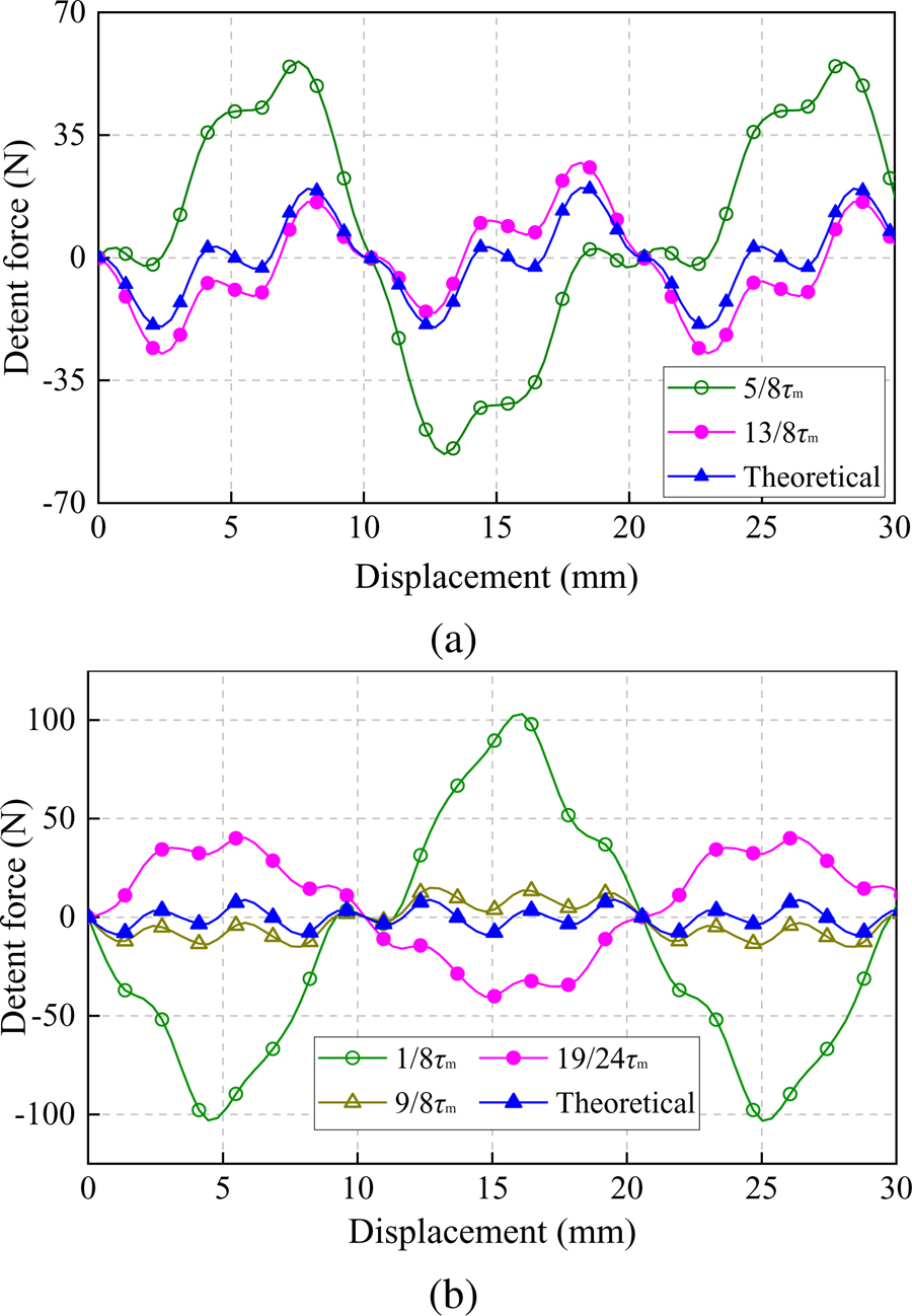
Figure 4: Whole detent force: (a) Modular I; (b) Modular II.
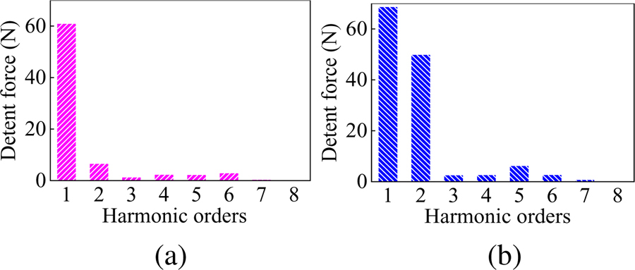
Figure 5: Harmonics distribution of unit detent force: (a) Modular I; (b) Modular II.
Figure 4 show the whole detent forces of Modular I and II under the different lengths of the flux barrier. For Modular I and II, both the whole detent forces are decreased as the flux barrier lengths are increased, which indicates that the magnetic coupling effect exists between unit generators and exerts a negative effect on the whole detent force. Hence, the flux barrier length should reach a certain length to reduce the influence of the magnetic coupling effect. When the flux barrier length of Modular I is 13/8 and that of Modular II is 9/8, the whole detent force is 27.39 N and 15.01 N, which is 35.86% and 67.71% higher than the theoretical value of 20.16N and 8.95 N, respectively. This means that the magnetic coupling effect needs to be further suppressed by other methods under a certain flux barrier length.
Moreover, the Fourier analysis results of unit detent force, as shown in Fig. 5, indicate that the second and its multiple components for Modular I are relatively large, and the third and its multiple components of Modular II are relatively little. So, according to the relationship between the whole detent force and the unit detent force in Section II-C, the theoretical whole detent force of the Modular I is relatively large, and that of the Modular II is relatively little, which are 20.16 N and 8.95 N, respectively. Hence, the actual whole detent force of Modular I is greater than that of Modular II, although the magnetic barrier length of Modular I is larger than that of Modular II, for example, when the magnetic barrier length is 13/8 and 9/8, respectively. Consequently, the whole detent force can be diminished by the reduction of the remaining harmonics in the unit detent force.
From the aforementioned analysis, it can be found that the whole detent force results from the magnetic coupling effect and remaining harmonics in the unit detent force. If both these contributing elements decrease, the whole detent force will decrease, and this can guide the optimization needed to reduce the detent force.
III. DETENT FORCE MINIMIZATION
In this section, the whole detent force is further reduced. Based on the analysis above, the whole detent forces of Modular I and Modular II are large, which are due not only to the magnetic coupling effect between unit generators but also to the remaining harmonic components in the unit detent force. Therefore, the whole detent force can be further reduced by suppressing the magnetic coupling effect, as well as reducing the remaining harmonics components.
A. Suppression of the magnetic coupling effect
The magnetic coupling effect exists between unit generators. Set Modular I with a flux barrier length of 13/8 as an example with which to analyze the magnetic coupling effect. The magnetic flux line distribution of the flux barrier is shown in Fig. 6 (a). The magnetic flux lines indicated by blue ellipses pass through the flux barrier or mover and connect the two adjacent unit generators, resulting in magnetic coupling. This is because the PMs on both sides of the flux barrier are magnetized in the same direction, and thus the equivalent magnetomotive force between two ends increases, which leads to the enhancement of the connection between adjacent unit generators. Hence, these magnetic flux lines can be suppressed by changing the magnetization direction of one of the PMs. Figure 6 (b) shows the magnetic flux line after changing the magnetization direction, i.e., reversed magnetization. The magnetic flux lines in the flux barrier are greatly suppressed, which indicates that the magnetic coupling effect is weakened.
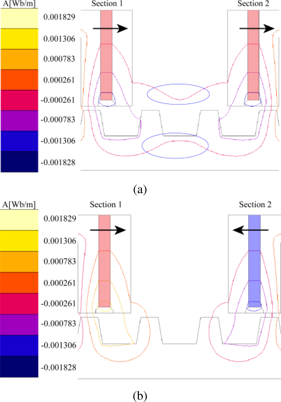
Figure 6: Magnetic flux line distribution: (a) same magnetization; (b) reversed magnetization.
Table 2: Comparison of the whole detent force
| Flux Barrier Length | Same Magnetization | Reversed Magnetization | Theoretical |
|---|---|---|---|
| 5/8 | 56.05 N | 31.35 N | 20.16 N |
| 13/8 | 27.39 N | 23.60 N |
Table 2 lists the comparison of the whole detent force of Modular I under two different magnetization directions. Compared with the whole detent force with the same magnetization, when the flux barrier length is 5/8 and 13/8, the whole detent force with the reversed magnetization declines by 44.07 and 13.84% respectively, but it is still greater than the theoretical value. It proves that the above method can suppress the magnetic coupling effect to a certain extent.
B. Reduction of remaining harmonics
Without considering the magnetic coupling effect, the whole detent force is the superposition of the remaining harmonics in the unit detent force. Thus, the whole detent force can be reduced through the diminishment of the remaining harmonics, which are the second and its multiple harmonics and the third and its multiple harmonics for Modular I and Modular II, respectively. According to the aforementioned literature, the end teeth width w and mover teeth coefficient k (k= w/w: the ratio of the mover teeth width w to the stator teeth width w) have a great influence on the detent force [23, 24]. Therefore, the above two parameters should be adjusted to reduce the remaining harmonics in the unit detent force.
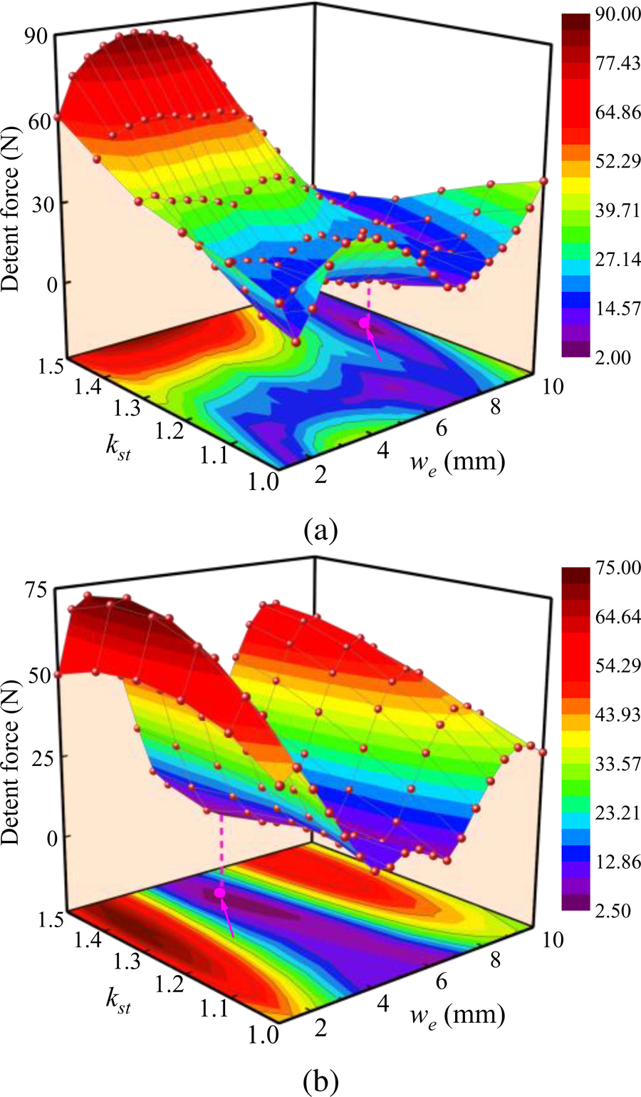
Figure 7: Whole detent force: (a) Modular I; (b) Modular II.
Figure 7 show the whole detent force of Modular I calculated by equation (12), and that of Modular II calculated by equation (13). For Modular I, when the end teeth width and mover teeth coefficient are 9 mm and 1.3 respectively – indicated by a magenta dot in Fig. 7 (a) – the minimum amplitude of the whole detent force is 2.46N. The corresponding flux barrier length can then be determined, although theoretically there are countless values for the flux barrier length because of k in equation (1) with countless values. According to equation (1), the flux barrier length can be /3, 4/3, or 7/3 (k = 8, 9, and 10), etc. Considering a certain flux barrier length to suppress the magnetic coupling effect and the stator volume limitation, the flux barrier length is selected as 4/3 (k=9). For Modular II, under the same mover teeth coefficient, the whole detent force initially decreases and then rises with the increase of the end teeth width. Within the end teeth width range from 4 mm to 6 mm, the whole detent force is relatively small, in which the minimum value is 2.65N when the end teeth width and mover teeth coefficient are 5 mm and 1.4 respectively, as shown by the magenta dot in Fig. 7 (b). Then, according to the determined end teeth width and combined with equation (2), the flux barrier length of Modular II is equal to 2/9, 8/9, 11/9, or 17/9 (k = 6 and 7), and so on. Finally, under comprehensive consideration, the flux barrier length is determined to be 11/9, with k = 7 and minus sign in equation (2).
IV. COMPARATIVE ANALYSIS
In this section, the three TFSPMLGs, including the initial TFSPMLG, Modular I, and Modular II, are analyzed comparatively by 2D-FEA. Apart from the end teeth width and mover teeth coefficient, all other parameters are identical.
A. Winding arrangement of the sectional modular TFSPMLG
The winding arrangements need to be determined first. The electrical degrees between two adjacent coil-EMF vectors can be calculated by [25]:
| (15) |
where N and N denote the number of stator slots and mover poles, respectively. In this paper, the of the 12s/14p PMLSM is 60, thus the phase sequences of the initial TFSPMLGs are A-C-B-A-C-B-A-C-B-A-C-B, as shown in Fig. 1 (b).
The coil connection in the sectional modular TFSPMLG is different from the traditional one, due to the existence of the flux barrier. In Fig. 3, there are six and four coils in each section, and the phase sequences of the coils in Section 1 are A-C-B-A-C-B and A-C-B-A, respectively, which is the same as that of the corresponding part in the initial TFSPMLG. However, the coil connections of Sections 2 and 3 need to be adjusted to obtain symmetrical three-phasecomplementary windings.
For Modular I, the sum of the sectional stator and flux barrier length satisfies equation (7), which means that the relative positional difference between the first coil of Sections 1 and 2 is /2, corresponding to an electrical angle of 180. In addition, to weaken the magnetic coupling effect in Section III-A, the magnetization direction of the PMs is changed, which again results in the shift of the coil-EMF vector, with an electrical angle of 180. Hence, the coil-EMF vector of the two sections is the same, and the phase sequence in Section 2 of Modular I is also A-C-B-A-C-B. The phase coil vector and the winding arrangement can be determined, as shown in Figs. 8 and 10 (a), where coil X and X’ in Fig. 8 represent opposite polarity.
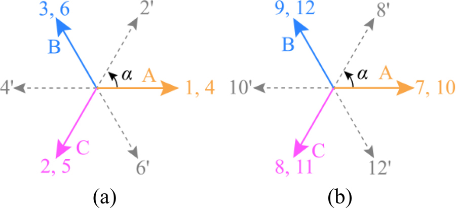
Figure 8: Phase coil vector of Modular I: (a) Section 1; (b) Section 2.
For Modular II, the sum of the sectional stator and flux barrier length satisfies equation (2) with k = 7 and minus sign, which indicates that the first coil of Section 2 (the 5th one) lags behind that of Section 1 by the electrical angle of 120. Likewise, the first coil of Section 3 (the 9th one) also lags 120 behind that of Section 2. Therefore, in consideration of the magnetization direction of the PMs, the coil-EMF vector of Sections 2 and 3 can be determined as shown in Figs. 9 (b) and (c), respectively. It can be found from Fig. 9 that coils No. 1, 4, 7’, and 10, coils No. 2, 5’, 8’, and 11, and coils No. 3, 6’, 9, and 12 all have the same electrical angles, and the phase difference between them is a 120 electrical angle. Meanwhile, coils No. 5, 6, 7, and 8 in Section 2 are with opposite polarity, which are marked with apostrophes, thus they are wound reversely. So, the coil connection in Sections 2 and 3 are Z-Y-X-Z and B-A-C-B, respectively, and Fig. 10 (b) shows its winding arrangement. The idealized arrangement of both the three-phase complementary windings confirm that the theoretical analysis in Section II-B is correct.
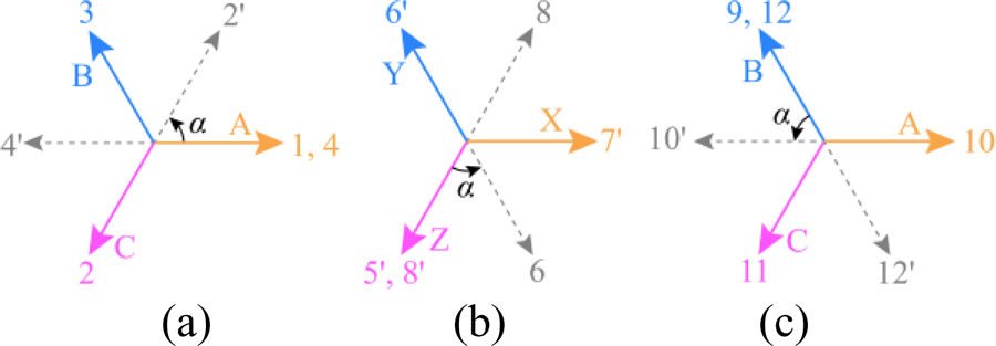
Figure 9: Phase coil vector of Modular II: (a) Section 1; (b) Section 2; (c) Section 3.
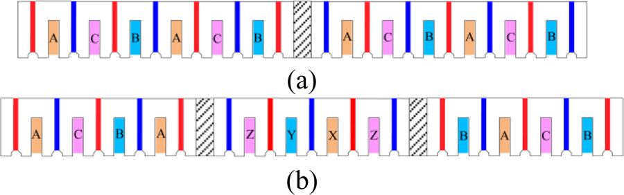
Figure 10: Winding arrangements: (a) Modular I; (b) Modular II.
B. Performances comparison
Figure 11 shows the detent force curves of three TFSPMLGs, of which the amplitudes are 63.09, 8.97, and 5.41 N, separately. Compared with the initial structure, the latter two structures are reduced by 85.78% and 91.42%, respectively. It is clear that for TFSPMLG, the detent force can be significantly suppressed by adopting the sectional modular structure scheme. In addition, though both the actual detent forces of the Modulars I and II are larger than the theoretical detent forces with the amplitude 2.46 and 2.65 N due to the magnetic coupling effect, they are at an acceptable level. It proves the effectiveness of the sectional modular technology scheme for the TFSPMLG.
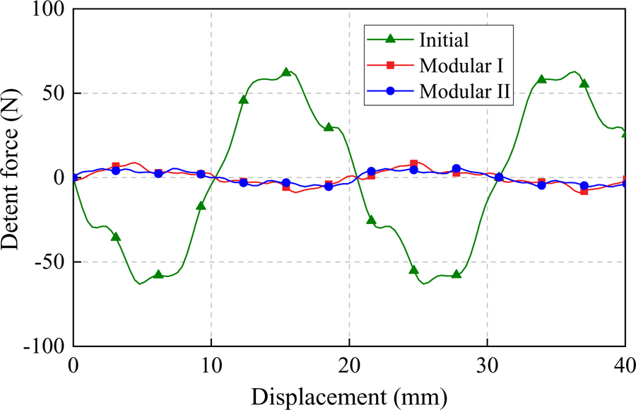
Figure 11: Detent force curves of three TFSPMLGs.
The back-EMF curves of three TFSPMLGs are shown in Fig. 12. It is worth noting that, for Modulars I and II, the back EMFs are the sum of that of each section. From the picture, the three back-EMF curves almost coincide, with very little difference between the three. The Fourier analysis results show that the fundamental components are 42.94, 43.17, and 44.29 V, with the total harmonic distortion (THD) 2.42%, 4.08%, and 1.47%, respectively. It can be found that, compared with the initial TFSPMLG, the THD of Modular I is increased greatly, whereas that of Modular II is decreased.
For Modular I, the main reasons can be described as follows: on the one hand, the winding arrangement of Section 2 is the same as that of Section 1 – see Fig. 10 (a) – with the result that the middle phase (phase C) is always in the middle of the sectional stator, and the side end phase (phases A and B) are always at the ends; on the other hand, the two-section structure is adopted to double the number of ends from 2 to 4; finally, the magnetic circuit of the three-phase windings is more unbalanced in such way that the corresponding THD increases. Different from that of Modular I, the arrangement of three-phase windings for Modular II, shown in Fig. 10 (b), is spatially symmetrical in that the numbers of each phase coil located on the side ends are the same, leading to the decrease of THD. Therefore, Modular II has better back-EMF characteristics.
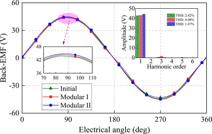
Figure 12: Back EMF of three TFSPMLGs.
The electromagnetic forces of three TFSPMLGs are compared in the resistive load with 10 , as shown in Fig. 13. The average electromagnetic forces are 219.56, 220.85, and 230.01 N, and the electromagnetic force ripples, which is the ratio of the peak-to-peak value to the average value of electromagnetic force, are 59.78%, 30.21%, and 5.81%, respectively. Compared with the initial TFSPMLG, the electromagnetic force ripples of the sectional modular TFSPMLGs are suppressed due to the drop of detent force without sacrificing the average electromagnetic force.
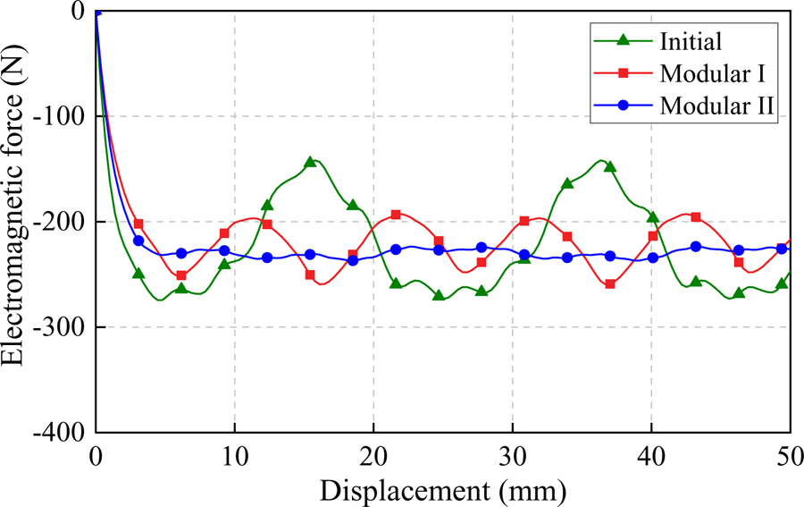
Figure 13: Electromagnetic force curves of three TFSPMLGs.
However, according to the above analysis results for Modular I, the reduction degree of the electromagnetic force ripple is much lower than that of the detent force. This is because the force ripple is not only related to the detent force but is also associated with the harmonics in the back EMF [18]. For Modular II, both the detent force and back-EMF THD are declined, thus the electromagnetic force ripple is small.
The efficiency of three TFSPMLGs is calculated only considering the copper and core losses as:
| (16) |
where , P, P, and P are efficiency, electromagnetic power, copper loss, and core loss, respectively. The electromagnetic power is the product of the electromagnetic force and the mover velocity, and copper loss and core loss are computed by 2D-FEA, thus efficiency canbe obtained.
Table 3: Comparison summary
| Item | Initial | Modular I | Modular II |
|---|---|---|---|
| Amplitude of detent force (N) | 63.09 | 8.97 | 5.41 |
| Back-EMF (V) | 42.94 | 43.17 | 44.29 |
| THD (%) | 2.42 | 4.08 | 1.47 |
| Average electromagnetic force (N) | 219.56 | 220.85 | 230.01 |
| Electromagnetic force ripple (%) | 59.78 | 30.21 | 5.81 |
| Core losses (W) | 5.95 | 6.85 | 7.23 |
| Copper losses (W) | 8.86 | 8.91 | 9.28 |
| Efficiency (%) | 93.43 | 93.07 | 93.04 |
Table 3 lists the comparison results of three TFSPMLGs. Based on the analysis of the detent force, back-EMF, and electromagnetic force, Modular II not only reduces the detent force most effectively, but also possesses the optimal back-EMF and electromagnetic force characteristics, with nearly the same efficiency. In addition, each sectional stator structure in Modular II is the same, thus the manufacture is simple. Hence, the proposed Modular II is a better choice for the TFSPMLG.
V. CONCLUSION
In this paper, sectional modular TFSPMLGs are proposed and investigated to reduce the detent force by adopting two-section and three-section structures, respectively. The sectional modular technology applies the particular harmonics in the unit detent force of each section to mutually offset, thereby reducing the whole detent force. First, the topology of TFSPMLG is described, and its detent force is analyzed. Then, the feasibility, detent force suppression principle, and the effects that the sectional modular structures exert on the detent force are investigated for the two sectional modularTFSPMLGs.
In addition, to suppress the magnetic coupling effect and reduce the remaining harmonics, two minimization methods are presented. Finally, electromagnetic performance comparisons between the initial TFSPMLG, Modular I, and Modular II are conducted based on 2D-FEA with respect to detent force, EMF, and electromagnetic force. The results show that the sectional modular technology structure is proved to effectively reduce the detent force without sacrificing the back-EMF and average electromagnetic force, especially with respect to Modular II.
ACKNOWLEDGMENT
This work was supported by the Natural Science Foundation of China (52207067, 51777060), the Major Special Project for Collaborative Innovation in Zhengzhou (20XTZX12023), the China Postdoctoral Science Foundation (2020M682342), and the Henan Province Key R&D and promotion projects (Scientific and Technological Breakthrough) (232102221016). This research was also funded by the Science and Technology Funds of the North China Institute of Science and Technology under grant number JSJ1204B and JD2013B01.
REFERENCES
[1] O. Farrok, M. R. Islam, M. R. I. Sheikh, Y. Guo, and J. G. Zhu, “A split translator secondary stator permanent magnet linear generator for oceanic wave energy conversion,” IEEE Trans. Ind. Electron., vol. 65, no. 9, pp. 7600-7608, Sep. 2018.
[2] C. Zheng, C. Li, J. Pan, M. Liu, and L. Xia, “An overview of global ocean wind energy resource evaluations,” Renewable Sustain. Energy Rev., vol. 53, pp. 1240-1251, Jan. 2016.
[3] L. Xu, C. Zhang, and X. Zhu, “Decoupling control of a dual-stator linear and rotary permanent magnet generator for offshore joint wind and wave energy conversion system,” IET Elect. Power Appl., vol. 14, no. 4, pp. 561-569, Apr. 2020.
[4] L. Szabó, “On the use of rotary-linear generators in floating hybrid wind and wave energy conversion systems,” Proc. 21st IEEE Int. Conf. AQTR, Cluj-Napoca, Romania, pp. 1-6, May 2018.
[5] J. Wang, W. Wang, K. Atallah, and D. Howe, “Design considerations for tubular flux-switching permanent magnet machines,” IEEE Trans. Magn., vol. 44, no. 11, pp. 4026-4032, Nov. 2008.
[6] G. Zhang, R. Nie, J. Si, C. Gan, and Y. Hu, “Optimal design of a novel double-stator linear-rotary flux-switching permanent-magnet generator for offshore wind-wave energy conversion,” Proc. IEEE Energy Convers. Congr. Expo., Vancouver, BC, Canada, pp. 4300-4305, Oct. 2021.
[7] R. Nie, J. Si, S. Xu, G. Zhang, Z. Li, and Z. Cheng, “Optimization of a novel linear-rotary permanent magnet generator for wind-wave combined energy conversion via TOPSIS decision making,” Proc. 13th Int. Symp. Linear Drives for Ind. Appl., Wuhan, China, pp. 1-6, July 2021.
[8] Q. Liu, H. Yu, M. Hu, C. Liu, J. Zhang, L. Huang, and S. Zhou, “Cogging force reduction of double-sided linear flux-switching permanent magnet machine for direct drives,” IEEE Trans. Magn., vol. 49, no. 5, pp. 2275-2278, May 2013.
[9] S. Zhou, H. Yu, M. Hu, C. Jiang, and L. Hao, “Reduction of cogging force in a linear flux-switching permanent-magnet brushless AC machine for direct-drive applications,” IEEE Trans. Magn., vol. 47, no. 10, pp. 3252-3255, Oct. 2011.
[10] S. Ali, J. Ikram, C. P. Devereux, S. S. H. Bukhari, S. A. Khan, N. Khan, and J.-S. Ro, “Reduction of cogging torque in AFPM machine using elliptical-trapezoidal-shaped permanent magnet,” Applied Computational Electromagnetics Society (ACES) Journal, vol. 36, no. 8, pp. 1090-1098,Aug. 2021.
[11] S. Amin, S. Madanzadeh, S. Khan, S. S. H. Bukhari, F. Akhtar, and J.-S. Ro, “Effect of the magnet shape on the performance of coreless axial flux permanent magnet synchronous generator,” Electrical Engineering, vol. 104, no. 2, pp. 959-968, Apr. 2022.
[12] R. Cao, D. Shen, and W. Hua, “Research on detent force characteristics of a linear flux-switching permanent-magnet motor,” IEEE Trans. Energy Convers., vol. 36, no. 4, pp. 2998-3006, Dec. 2021.
[13] C.-F. Wang, J.-X. Shen, Y. Wang, L.-L. Wang, and M.-J. Jin, “A new method for reduction of detent force in permanent magnet flux-switching linear motors,” IEEE Trans. Magn., vol. 45, no. 6, pp. 2843-2846, June 2009.
[14] S. Wang, Y. Wang, C. Liu, G. Lei, J. Zhu, and Y. Guo, “Detent force minimization of a tubular flux-switching permanent magnet motor using un-equal width stator slots based on Taguchi method,” IEEE Trans. Appl. Supercond., vol. 30, no. 4, June 2020.
[15] J. Zhao, Q. Mou, K. Guo, X. Liu, J. Li, and Y. Guo, “Reduction of the detent force in a flux-switching permanent magnet linear motor,” IEEE Trans. Energy Convers., vol. 34, no. 3, pp. 1695-1705, Sep. 2019.
[16] B. Li, J. Zhao, X. Liu, Y. Guo, H. Hu, and J. Li, “Detent force reduction of an arc-linear permanent-magnet synchronous motor by using compensation windings,” IEEE Trans. Ind. Electron., vol. 64, no. 4, pp. 3001-3011, Apr. 2017.
[17] T. Yao, W. Zhao, F. Bian, L. Chen, and X. Zhu, “Design and analysis of a novel modular-stator tubular permanent-magnet Vernier motor,” IEEE Trans. Appl. Supercond., vol. 28, no. 3, Art. no. 0601105, Apr. 2018.
[18] X. Huang, Z. Qian, Q. Tan, J. Li, and B. Zhou, “Suppressing the thrust ripple of the permanent magnet linear synchronous motors with different pole structures by setting the modular primary structures differently,” IEEE Trans. Energy Convers., vol. 33, no. 4, pp. 1815-1824, Dec. 2018.
[19] J. Li, X. Huang, B. Zhou, H. Yu, and Q. Huang, “Design principle of a 16-pole 18-slot two-sectional modular permanent magnet linear synchronous motor with optimisation of its end tooth,” IET Elect. Power Appl., vol. 14, no.3, pp. 441-447, Mar. 2020.
[20] X. Z. Huang, J. Li, Q. Tan, Z. Y. Qian, C. Zhang, and L. Li, “Sectional combinations of the modular tubular permanent magnet linear motor and the optimization design,” IEEE Trans. Ind. Electron., vol. 65, no. 12, pp. 9658-9667, Dec. 2018.
[21] Q. Tan, M. Wang, L. Li, and J. Li, “Research on noninteger pole number for segmental permanent magnet linear synchronous motor,” IEEE Trans. Ind. Electron., vol. 68, no. 5, pp. 4120-4130, May 2021.
[22] Q. Tan, X. Huang, L. Li, and M. Wang, “Magnetic field analysis and flux barrier design for modular permanent magnet linear synchronous motor,” IEEE Trans. Ind. Electron., vol. 67, no. 5, pp. 3891-3900, May 2020.
[23] R. Cao, M. Cheng, and W. Hua, “Investigation and general design principle of a new series of complementary and modular linear FSPM motors,” IEEE Trans. Ind. Electron., vol. 60, no. 12, pp. 5436-5446, Dec. 2013.
[24] R. Cao, M. Cheng, C. C. Mi, and W. Hua, “Influence of leading design parameters on the force performance of a complementary and modular linear flux-switching permanent-magnet motor,” IEEE Trans. Ind. Electron., vol. 61, no. 5, pp. 2165-2175, May 2014.
[25] J. T. Chen and Z. Q. Zhu, “Winding configurations and optimal stator and rotor pole combination of flux-switching PM brushless AC machines,” IEEE Trans. Energy Convers., vol. 25, no. 2, pp. 293-302, June 2010.
BIOGRAPHIES

Guozhen Zhang was born in Anhui province, China, in 1996. He received the B.S. degree in Electrical Engineering from the Henan University of Technology in 2020. He is currently working toward the M.S. degree in Electrical Engineering with the School of Electrical and Information Engineering, Zhengzhou University, Zhengzhou, China. His current research interests include the design and optimization of two-degree-of-freedom machines and linear machines.

Rui Nie received the B.S. degree in Electrical Engineering from Henan Polytechnic University, Jiaozuo, China, in 2015, and the Ph.D. degree in Electrical Engineering from the China University of Mining and Technology, Xuzhou, China, in 2020. She is currently an assistant research fellow at Zhengzhou University. Her current research interests include two-degree-of-freedom machines, linear motor design and control, and renewable energy generation technology.

Jikai Si received the B.S. degree in Electrical Engineering and Automation from the Jiaozuo Institute of Technology, Jiaozuo, China, in 1998; the M.S. degree in electrical engineering from Henan Polytechnic University, Jiaozuo, China, in 2005; and the Ph.D. degree in Power Electronics and Power Drives from the School of Information and Electrical Engineering, China University of Mining and Technology, Xuzhou, China, in 2008. He is currently a Distinguished Professor with the School of Electrical and Information Engineering, Zhengzhou University. He has authored and co-authored more than 160 technical papers in these areas. His main research interests include the theory, application, and control of the special motor. Dr. Si is a Member of the Green Motor System Professional Committee, China.

Xiaohui Feng received the B.S. degree in Electrical Engineering and automation from the Jiaozuo Institute of Technology, Jiaozuo, China, in 1998, and the M.S. degree in Electrical Engineering from Henan Polytechnic University, Jiaozuo, China, in 2004. She is currently an associate Professor with the School of Electrical Engineering, North China Institute of Science and Technology. Her main research interests include linear motor design and control, control theory, and control engineering.

Changli Wang received the M.S. degree in Software Engineering from the University of Electronic Science and Technology of China, Chengdu, China, in 2009. He is currently a senior engineer with the School of Computer Science, North China Institute of Science and Technology. His main research interests include software engineering.
ACES JOURNAL, Vol. 38, No. 4, 286–296
doi: 10.13052/2023.ACES.J.380408
© 2023 River Publishers