Electromagnetic and Thermal Analysis of a 6/4 Induction Switched Reluctance Machine for Electric Vehicle Application
Ali Madanimohammadi, Mohammadali Abbasian, Majid Delshad, and Hadi Saghafi
Department of Engineering
Islamic Azad University, Isfahan (Khorasgan) Branch, Isfahan 39998-81551, Iran
a.madani.m@khuisf.ac.ir, m.abbasian@khuisf.ac.ir, delshad@khuisf.ac.ir, h.saghafi@khuisf.ac.ir
Submitted On: June 3, 2022; Accepted On: May 18, 2023
ABSTRACT
In this paper, an oil-cooling induction switched reluctance machine (ISRM) is offered. The stator and rotor of the electric machine are non-segmental. However, by placing coils on the rotor, a short magnetic flux path is achieved in the rotor and stator cores. As a result, a higher torque with lower losses is generated. This configuration can be used in high-power electric motors for electric and hybrid vehicles. ISRM is a novel machine and there is a lack of access to its operation and data characteristics. ISRM can be designed in different configurations with various stator and rotor pole numbers and winding strategies. In this study, an oil-cooling three-phase ISRM with 6 stator poles and 4 rotor poles was considered. Firstly, a 2D finite element model of it is created, and its magnetic properties extracted, the flux path, torque and efficiency of the ISRM are calculated, and the results are presented. Secondly, the thermal performance of the motor is analyzed using ANSYS Motor-Cad software. Finally, a prototype of the ISRM and its appropriate drive with the oil cooling system is built and tested. The experimental results and conclusions which prove the ability of the presented machine are presented in the last parts of the paper.
Index Terms: analysis, electric vehicle, finite element, induction motor, oil spray cooling, short flux path, switched reluctance motor.
I. INTRODUCTION
In recent decades, the number of vehicles that consume fossil fuels has been increasing all over the world. This leads to the generation of toxic gases and materials, which is a serious threat to human health and the environment. Replacing internal combustion engines with electric powertrains is an appropriate solution to reduce the dangerous pollutants produced by traditional vehicles. Electric machines are the most essential part of electric powertrains. For electric vehicle applications, high-performance electric machines are required. They should be lightweight, compact, low-cost, efficient, easily to manufacture, and above all,reliable [1].
Permanent magnet machines, such as Permanent Magnet Synchronous Machines (PMSM) are implemented in hybrid and electric vehicles due to their high torque and efficiency [2]. These machines use permanent magnets that contain rare earth materials such as Neodymium and Samarium. On the other hand, the high cost of permanent magnet materials and their limited supply have been identified as significant challenges for the electric vehicle industry in the future [3].
There are other electric motors that could be considered to be used as a propulsion system for electric vehicles. The most famous one is the induction machine, which has been implemented in the powertrain of Tesla cars’ previous models. Induction machines do not contain permanent magnets but still have an acceptable power density and efficiency. However, they don’t have the efficiency and power density as high as the permanent magnet motors [4]. As a result, the new models of Tesla cars replaced PMSM with an induction motor as a traction motor.
Some researchers have been working on switched reluctance machines (SRMs) instead of induction machines or permanent magnet machines in the powertrain of electric vehicles. SRMs consist of a straightforward structure and have fault-resistant performance under difficult operational circumstances [5]. The simplicity of an SRM is due to its rotor configuration, which does not contain either permanent magnets or conductors. In SRMs, only reluctance torque is the cause of torque generation. Simple structure, low cost, high-temperature resistant rotor, and high speed are the most essential advantages of the switched reluctance motors. Compared to a permanent magnet motor, switched reluctance motors contain some disadvantages, such as a lower level of torque density, a high level of torque ripple, noise, and vibration [6].
In recent years, many investigations have been done to improve the switched reluctance motor capabilities and advantages. The research shows this critical fact that only a small percentage of the electromechanical forces generated inside the SRMs are used to produce motion and produce torque. In fact, not only a large part of the force produced is a non-motional force, but it is also caused by motor noise and vibration. This is one of the primary defects of the SRMs that needs to be addressed. Many efforts have been made to design SRMs with a higher percentage of a motional force to achieve high torque motors with lower noise and vibration. For example, the double stator switched reluctance machine (DSSRM) was designed in 2010 with high torque density and low vibration [7]. DSSRM consists of a cylindrical hollow rotor and two stators. In this structure, short flux paths are created in the machine cores. It has been demonstrated that the implementation of this structure, can create more motional force, the torque density of a DSSRM is twice that when compared with the conventional SRM. In DSSRM topology, the non-motional force is declined, so the machine experiences lower noise and vibration. On the other hand, DSSRM has some drawbacks, and researchers are working to address them. For example, in electric vehicle applications, the inner stator, which contains high-current windings, is surrounded by the rotor. As a result, it isn’t easy to design a cooling system for the inner stator. Moreover, the rotor is composed of several ferromagnetic segments which are embedded in a non-ferromagnetic cylinder. This may hinder a straightforward realization of the rotor and other parts of the motor and urges us to design electric motors with a non-segmental rotor and stator.
There are other high torque and short flux path SRMs that have a segmental rotor or stator [8-10]. For instance, a segmented switched reluctance motor was introduced by Mecrow, with a segmental rotor and non-segmental stator [8]. In this electric machine, the rotor consists of ferromagnetic segments, which are fixed together by a non-ferromagnetic cage. This configuration is such that it prevents the flux from circuiting through all the stator yoke. This electric motor can produce 40% more torque than conventional SRMs of the same size. Another configuration of segmental switched reluctance motor has been proposed in [9]. In this structure, the rotor is segmental, and the stator is non-segmental. Like other segmental SRMs, this motor can produce higher torque compared to the conventional SRMs while generating a lower core loss. It should be mentioned that in segmental SRMs a minor deviation in the manufacturing and assembly process of segmented parts, can result in a non-uniform airgap between the rotor and stator. This can lead to mechanical problems during motor operation, such as a vibration increase in the motor [7].
If a switched reluctance machine can be designed with a non-segmental rotor and stator, and at the same time a short flux path is maintained in the motor core, appropriate results can be obtained. To this end, [11] has proposed a novel structure of an electric machine called ISRM. This machine can use the impact of magnetic induction and a short flux path to enhance the energy conversion efficiency of the generated force into motion and torque. This structure leads to a fundamental change in the design of electric motors and their optimization. In this motor, the integrated structure and the rotor conductors lead to a very short flux path. In the next section, more details about the operation principles of ISRM will be presented and a comprehensive analysis will be performed, using the finite element method.
ISRM can be designed with multiple poles and different coils. To investigate this novel structure, this paper examines a 6kw ISRM with 6 stator poles and 4 rotor poles. It is designed and analyzed using ANSYS Maxwell software. The results of the magnetic analysis are presented along with calculations of flux, torque, and efficiency. Also, the thermal performance of this motor, which uses an oil cooling system, is done using ANSYS Motor-Cad software. The 6kw ISRM is built and tested, and in the end the experimental results are presented.
II. ISRM
A. Machine topology
ISRM is a novel electrical machine but it has a conventional structure. It includes one inner rotor and one outer stator [11]. This is an advantage for this machine, because some of the novel electric machines which are presented for electric vehicle propulsion systems have an unconventional structure that makes the machine manufacturing process more difficult. The rotor of ISRM contains short-circuited coils. The rotor coils are not powered by an external source, but the current is induced while the rotor moves. During the rotor rotation, the magneto motive force (MMF) generated by the rotor coils prevents the flux from passing through the rotor yoke, leading to the creation of a short flux path.
ISRM can be designed in different types of poles and various winding strategies. Depending on the number of stator and rotor poles, the winding pitches can differ. In some configurations, the stator and rotor coils are full pitch, while in some other topologies, the stator and or rotor coils are short pitch. For instance, a 12/8 ISRM with short-pitch rotor coils and full-pitch stator coils are presented in [11].
The number of ISRM stator and rotor poles is selected as conventional SRMs. In this paper, ISRM with 6 stator poles and 4 rotor poles is investigated. Figure 1 shows a schematic of this three-phase ISRM. As illustrated in the figure, the stator and rotor coils are full pitch. Figure 2 shows the connection of windings. In ISRM, the rotor coils are not connected, contrary to the induction machine. Like conventional SRMs, the DC pulse is required to excite each phase of ISRM. These pulses are generated by the electric drive, respecting the rotor position. Conventional SRM drives can be implemented into ISRM without any modifications.
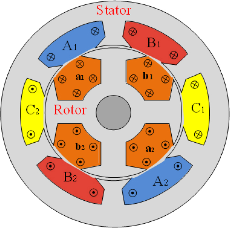
Figure 1: A 3-phase 6/4 ISRM.
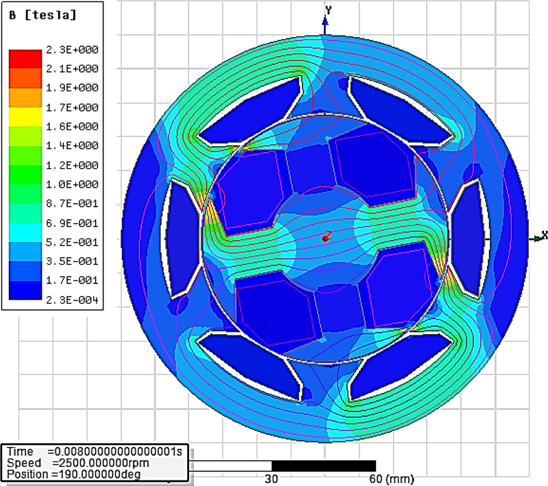
Figure 2: Flux path in ISRM without rotor winding.
If a phase of the ISRM is excited while the rotor is rotating, the magnetic field inside the rotor coils will change. This results in voltage induction in the short-circuited coils of the rotor, according to Faraday induction law. Based on Lenz’s law, the direction of the inductive electromotive forces in the rotor coils is opposed to the flux changes. Hence, the flux does not pass through the rotor core, which leads to a short flux path around the excited stator coil. The results of the finite element analysis to determine the flux path of ISRM will be presented in this paper.
B. Simulation of ISRM (6/4)
The two-dimensional model of a 6/4 ISRM with the characteristics shown in Table 1 is simulated using ANSYS Maxwell software.
Table 1: Specifications of the ISRM and SRM
| Parameter | Value |
|---|---|
| Housing diameter | 120 mm |
| Stator outer diameter | 100 mm |
| Motor length | 115 mm |
| Stack length | 50 mm |
| Air gap | 0.5 mm |
| Number of stator poles | 6 |
| Number of rotor poles | 4 |
| Turn number of stator coils | 100 |
| Turn number of rotor coils (ISRM) | 100 |
| Rated current | 80 A |
| Maximum current density | 20 A/mm |
| Rotor and stator material | M19 |
| Rated power (ISRM) | 6 kW |
| Rated power (SRM) | 3 kW |
| Cooling method | Direct oil cooling |
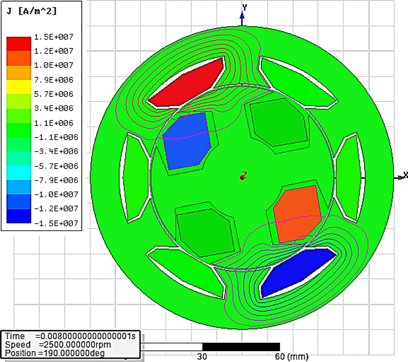
Figure 3: ISRM current distribution while phase A is excited.
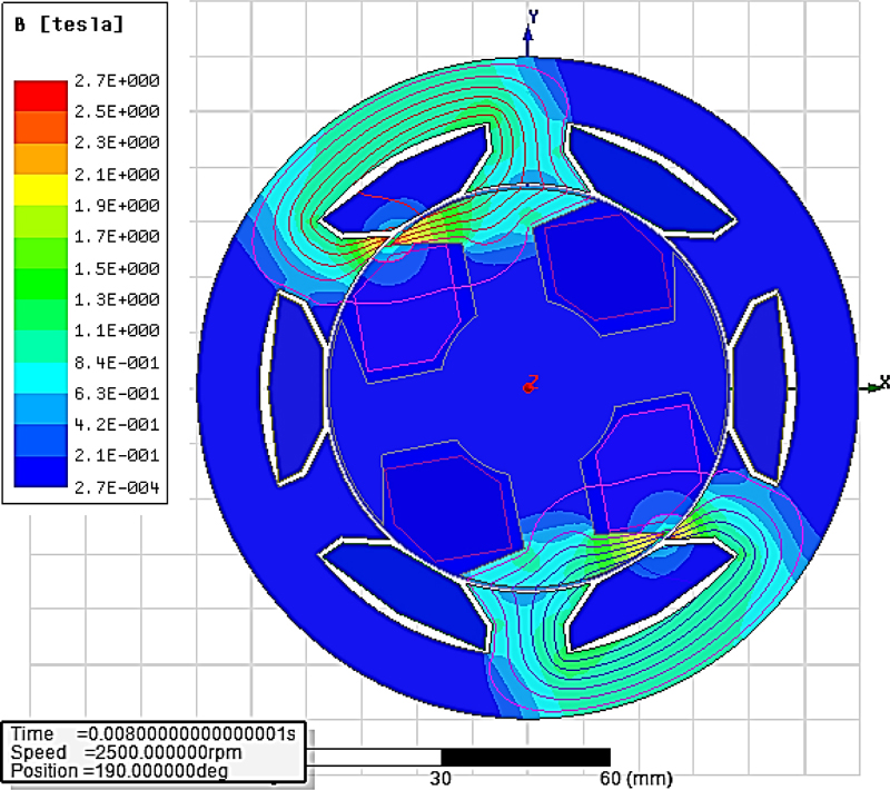
Figure 4: Flux distribution in the ISRM while phase A is excited.
This configuration has some advantages, such as high-speed capability and low switching loss, compared to the ISRMs with a high number of rotor and stator poles. The purpose of this simulation is to investigate the rotor short-circuit coil’s effect on the motor magnetic flux distribution. In the first step, phase A is powered, assuming that no coils are placed on the rotor. After simulating the motor in transient mode with the speed of 2500 rpm, the magnetic flux is calculated, and the results are presented. Figure 2 clearly shows that the magnetic flux paths are distributed in all poles of the rotor and stator. In the second step, the copper coils act as a short circuit on the rotor, and the same simulation is repeated again under the same conditions. The results of the new simulation can be seen in Figs. 3 and 4. As shown in the figures, the flux path is shortened, and the flux does not enter the rotor yoke due to the current induced in the rotor coils.
C. Torque characteristics of ISRM (6/4)
In this section, a conventional SRM and an ISRM are considered and the torques are calculated. Table 1 presents the related characteristics.
According to the transient finite element analysis of ISRM, phase A is excited with a constant current, while the rotor speed is constant. It should be noted that if the direct oil cooling method is applied to the rotor and stator windings, the current density of the conductors can increase up to 20 A/mm. In this case, the maximum phase current of the ISRM and the SRM will be 80 A. Considering this maximum current, the finite element method (FEM) analysis is performed in this study.
The reposition of the rotor is 45 degrees from unalignment to alignment. It should be noted that only two thirds of the considered torque range is used in the continuous operation mode (30 degrees). The FEM calculated results of the generated torque and the average torque of the ISRM (while the phase current is 80 A and the rotor speed is 2500 rpm) are presented in Figs. 5 and 6, respectively.
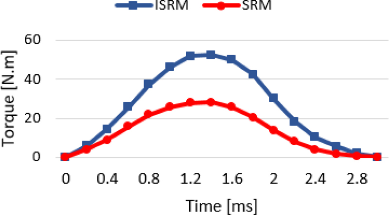
Figure 5: Total torque of ISRM and SRM.
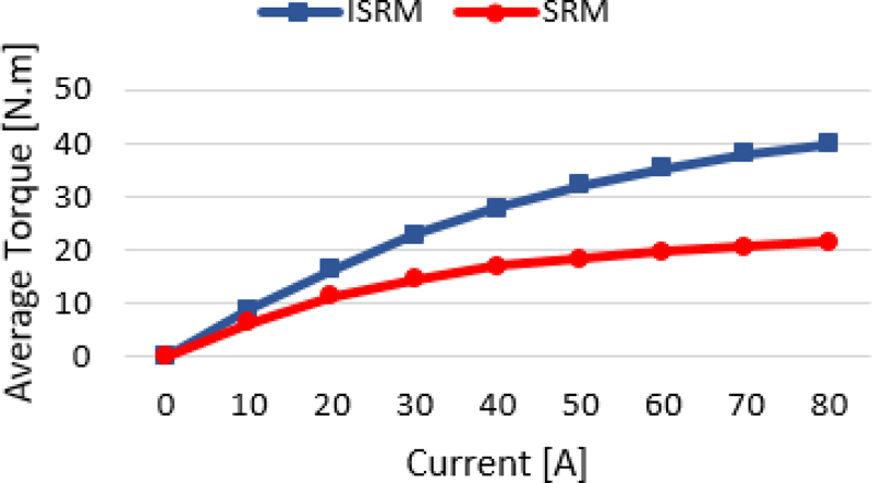
Figure 6: Average torque of the ISRM and the SRM in different currents.
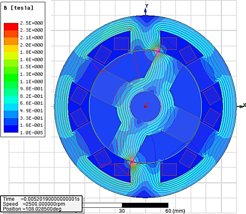
Figure 7: Flux distribution of the SRM while phase A is excited.
The same simulation (while the phase current is 80 A and the rotor speed is 2500 rpm) is performed for a conventional SRM, with the specifications presented in Table 1, and the simulation results are extracted. Figure 7 shows the flux distribution for the conventional SRM. The generated torque and the output torque of the SRM is calculated and presented in Fig. 5. The results demonstrate that ISRM can produce torque 85% higher than the equal-sized SRM. It should be mentioned that the ISRM torque has a high torque ripple. This is also the case for the conventional SRM. The torque ripple of ISRMs can be mitigated by the same techniques that are applied to conventional SRMs [12].
D. Evaluation of ISRM copper loss
While the rotor moves, the current is induced in the rotor coils. In this section, the induced current analysis in rotor coils is performed using the FEM. The current of the excited stator phase is assumed 80 A, and the rotor speed is 2500 rpm. The induced current of one of the rotor coils is shown in Fig. 8. Actually, current is induced in the rotor coil, which is under the excited stator phase. Firstly, when the rotor is in an unaligned position, the induced current in the rotor coil is equal to the stator phase current. The induced current in the rotor coils is variable, and it vanishes when the rotor is moving from the unaligned position toward the alignedposition.
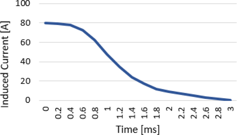
Figure 8: Induced current in a rotor winding.
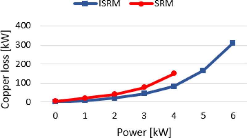
Figure 9: The copper loss of the ISRM compared to the copper loss of the conventional SRM at various output powers.
It may be assumed that implementing coils on the rotor of ISRM may enhance the overall copper loss of the machine. Actually, the rotor of ISRM generates copper loss due to the windings of the rotor, and this is a drawback compared to conventional SRMs which don’t have conductors on the rotor. But if the output torque compared to the overall copper loss of ISRM is high enough, it can be concluded that the efficiency of ISRM is high. In other words, a desired torque of ISRM is created with a lower stator current compared to SRM. This issue can be analyzed using the FEM method.
By FEM analysis and simulation of the ISRM and the SRM (see Table 1) in different currents, the copper loss in different output powers is calculated and presented for each motor in Fig. 9.
The analysis is considered with an oil cooling system, and the winding temperature is 100C. The motor speed is constant in these simulations (2500 rpm). It can be concluded that the ISRM copper loss is lower than the copper loss of the SRM in each output power. It can be found that the presence of the rotor coil does not increase the total copper loss of the ISRM at a specific output power compared to the SRM.
E. The ISRM cooling system
Thermal stress causes damage to various components of electric machines, such as coils, insulations, bearings, and magnets. The cooling system can be selected depending on the application of the electric machine. To increase the output torque of the machine, the current density of stator conductors has to be increased as much as possible. To this end, the heat generated due to the ohmic loss of high currents should be removed from the machine. High torque density electric machines which are implemented in electric vehicle propulsion systems require modern cooling techniques. Actually, in the conductors of these machines, the current density can reach up to 20 A/mm, which urges us to employ direct liquid cooling systems. Direct liquid cooling is accomplished using different techniques such as spray methods.
Oil spray cooling is an effective method that can remove high levels of heat from the inner parts of the motor. This method is implemented in recent models of Tesla and Toyota Prius. The coolant that is employed in oil spray cooling systems of electric machines must have specific properties. They need to be non-flammable, non-toxic, chemically stable, and inert. Moreover, they must have a low dielectric constant, high dielectric strength, and low density. For example, Florien liquids have these criteria and are richly used for direct liquid coolingsystems [13].
To analyze the thermal behavior of the electric machine, two numerical methods can be employed. The most accurate method is the finite element method, but it takes time to solve a problem using this technique. Another method is based on the lumped parameter thermal network, which can provide acceptable results quickly. Ansys Motor-CAD is a powerful tool that yields admissible analysis using the lumped parameter thermal network technique.
In this paper, Ansys Motor-Cad is used to predict the thermal behavior of the 6/4 ISRM. Firstly, the ISRM model is built into the software, and the losses of all parts of the machine which are calculated in Ansys Maxwell are imported. Then, oil-spray cooling is chosen as the cooling method of the electric machine. Automatic transmission fluid, ATF134 with a density of 812.5kg/m3, and specific heat of 2.030J/kg K was chosen as the coolant. Conditions applied to the thermal network are according to [13]. The rotational speed is 2000 rpm, and the ambient temperature is set at 40C. Moreover, the coolant inlet temperature is 40C and the minimum rate of published coolant flow is 1 L/min. In this cooling system, six nozzles with a diameter of 6.35mm are implemented around the motor.
Figure 10 shows the three-hour temperature-increase curve of the ISRM non-cooled motor. The final temperature of the stator winding is 168C, the rotor winding temperature is about 270C, and the stator pole temperature is about 164C. Furthermore, the rotor pole temperature is about 153C.
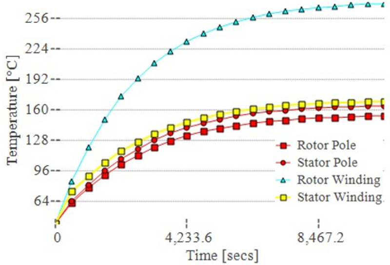
Figure 10: The three-hour temperature-increasing curve of the non-cooled motor.
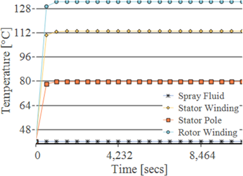
Figure 11: Comparison of the temperature curve of the ISRM with oil cooling.
Figure 11 shows the three-hour temperature-increase curve of the oil-cooled motor. The initial temperature of the motor winding is 40C. After one hour, the temperature of the motor parts is stable. The rotor winding temperature is about 130C and the stator winding temperature is about 100C. Furthermore, the stator pole temperature is about 80C. Figure 12 shows the thermal stress in different parts ofthe ISRM.
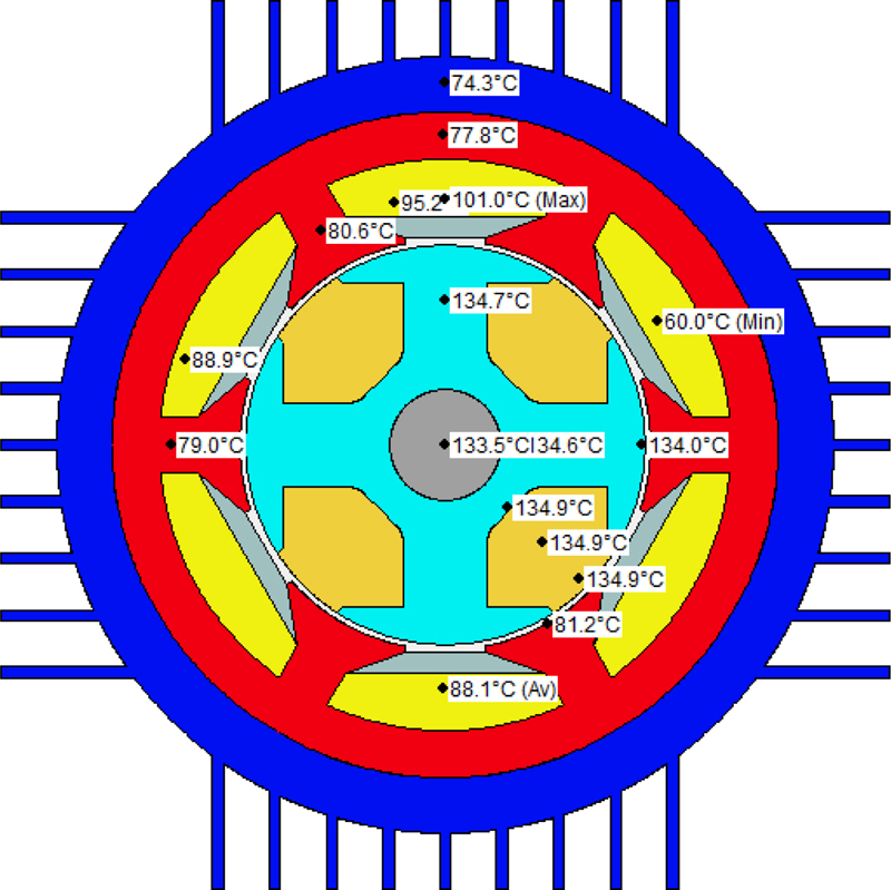
Figure 12: Thermal stress of the ISRM with oil coolingsystem.
III. EXPERIMENTAL RESULTS
For the real traction application of electric vehicles, at least a 50kW ISRM should have been designed and developed, but because of fund shortages, we were just able to construct a 6kW ISRM. This oil spray cooling ISRM, with the characteristics presented in Table 1, was built and tested. Figure 13 shows a block diagram of the experimental test setup of the ISRM. Figure 14 illustrates the ISRM experimental setup of the ISRM. The ISRM prototype can be seen in Fig. 15.
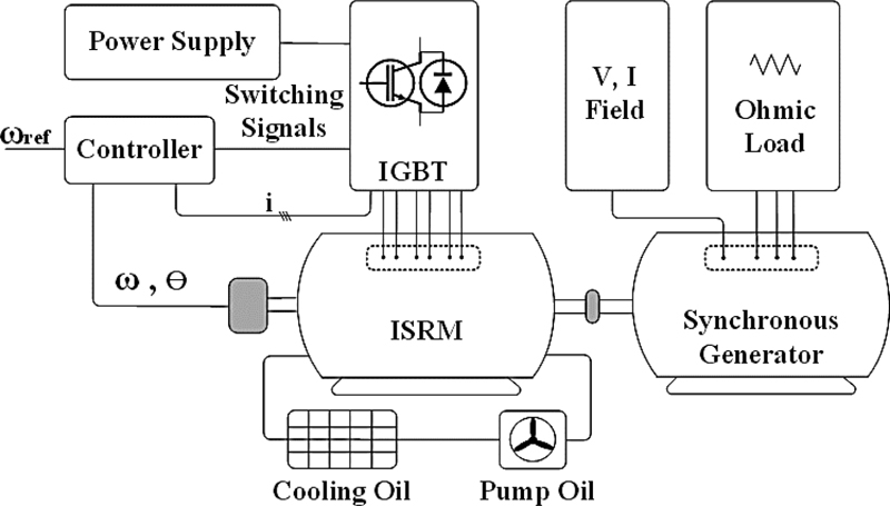
Figure 13: Block diagram of the experimental test setup of the ISRM.
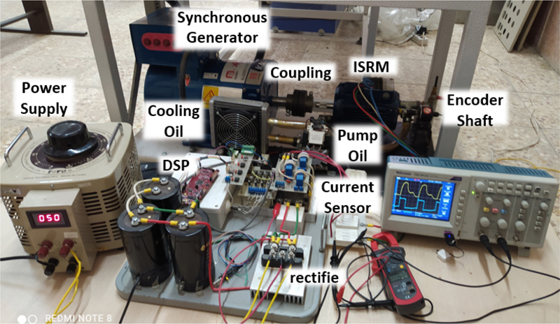
Figure 14: The experimental setup of the ISRM.

Figure 15: ISRM prototype.
The ISRM drive is precisely the same as conventional SRM drives. Firstly, the instantaneous position of the rotor must be determined at each step to turn the appropriate switches on and off. For this purpose, a shaft encoder (E50S) is mounted on the rotor shaft to determine the rotor position with an accuracy of one degree. Due to the utilization of a relative position sensor, a light sensor is installed on the motor shaft that detects the zero-degree position in each cycle. The advantage of this sensor is that the position error in each revolution is zero and provides enough accuracy to start and control the motor speed.
The ISRM drive includes several electronic boards. The LAUNCHXL-F28069M, C2000 Piccolo, is employed as a controller to generate sufficient gate pulses to turn IGBTs on and off at the appropriate time. A half-bridge converter using IGBT-IPM was considered as the switching circuit (7MBP75RA120). A snubber circuit is used to limit the voltage overshoots and protect the IGBTs.
In general, experimental measurements can be classified into direct and indirect methods. Direct methods use magnetic sensors to directly measure flux. To measure flux directly, methods are rarely used because the leakage flux affects accuracy. Indirect methods use phase voltage and current to estimate the flux. They can provide a simple structure, a low cost, andbetter accuracy.
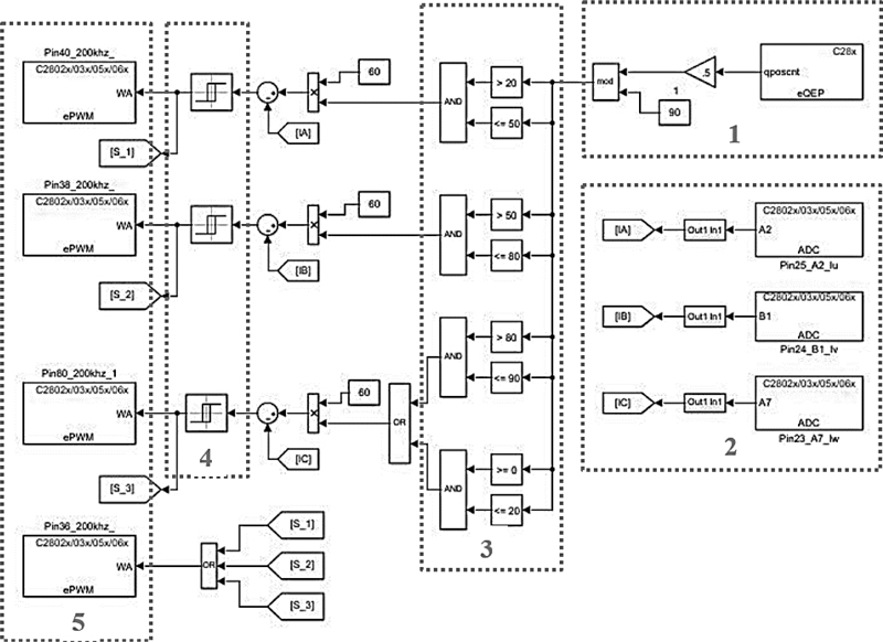
Figure 16: ISRM 6/4 control algorithm.
The control of the ISRM is similar to the conventional SRM. The control is based on the changes to the inductance diagram in terms of time. In fact, in motor mode, it should be done only during the time with a positive inductance slope and in generator mode only during the time with a negative inductance slope.
The ISRM control algorithm is shown in Fig. 16. It can be seen that in the figure, five boxes are specified, which respectively represent: encoder, current sensor, rotor position, hysteresis band and switches.
The ISRM prototype was tested for different currents and speeds to evaluate its operation. When the appropriate power switches are turned on, the corresponding stator phase is excited. When a phase is excited, the rotor rotates for 30C, from the unaligned position toward the aligned position. The switches will be turned off when the rotor is close to aligned position. The energy stored in the excited coils keeps the current in the same direction until this energy has completely vanished. As shown in Fig. 17, following continued excitation, a counterclockwise excitation pattern results in a clockwise rotation of the rotor and vice versa. Figure 17 includes two waveforms. The first figure illustrates the current of one phase of the stator winding and the second figure shows the voltage of the switch at the speed of 700 rpm.
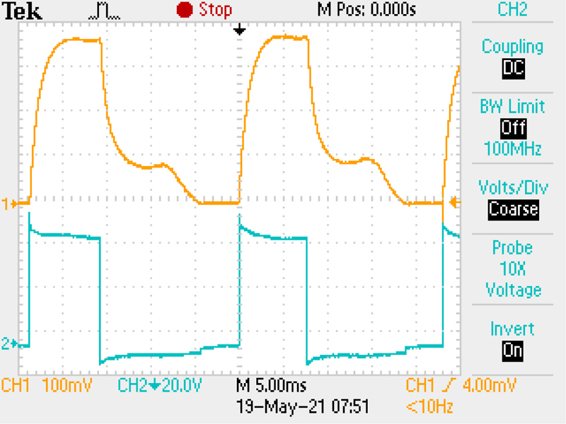
Figure 17: The phase current and voltage of the ISRM.
By measuring different voltages and currents, the torque and efficiency of the ISRM can be calculated. The efficiency of the ISRM was calculated at different speeds, and the results are presented in Fig. 18.
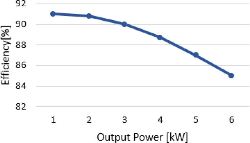
Figure 18: The efficiency of the ISRM at various output powers.
The rotor of an ISRM has copper losses due to the rotor windings, and this is a drawback compared to a conventional SRM with no conductors on the rotor. But if the output torque is high enough compared to the total copper losses of the ISRM, it can be concluded that the efficiency of the induction reluctance switch motor is increased. In other words, the desired torque is created in the ISRM motor with less stator current compared to the SRM. The torque is measured for different speeds and can be shown in Fig. 19.
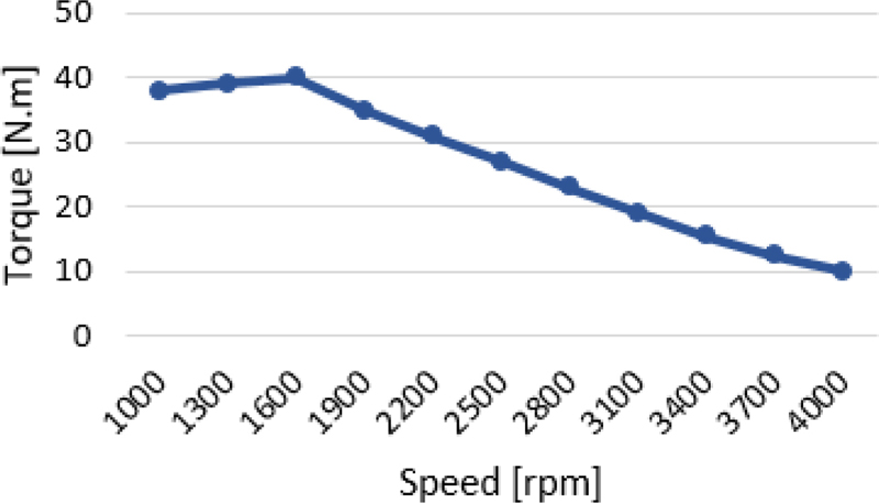
Figure 19: Torque versus speed of the ISRM.
The cooling oil is stored in an oil tank with a capacity of approximately 0.4 L/min, is delivered by an oil pump (maximum flow rate: 2 L/min) to the flow path, which is located in a hollow area of the shaft. The hollow flow path of the shaft has 6 nozzles to spray the cooling oil over the end windings. The oil absorbs the internal heat of the motor and then flows to the oil tank via a hole under the motor housing. The torque calculated from the FEM analysis and the experimental results are compared in Fig. 20.
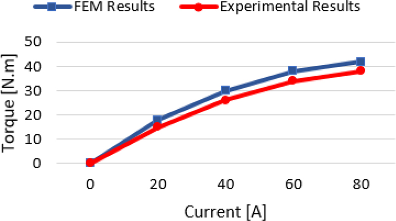
Figure 20: The FEM and experimental results of the ISRM.
Motor-CAD thermal analysis and the experimental results are compared in Fig. 21. A graph of steady-state temperatures shows the various parts the engine has reached. It can be observed that there is a desired accordance between simulation and experimental results.
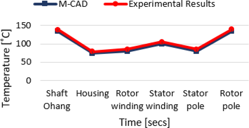
Figure 21: The M-CAD and experimental results of the ISRM.
IV. CONCLUSIONS
In this paper, a 6/4 ISRM with an oil cooling system for electric vehicle application was proposed. The 6 kW machine was built, and transient electromagnetic analysis was performed in ANSYS-Maxwell. The torque capability of the ISRM was examined and compared with a conventional SRM. The result confirms that the ISRM has 85% more torque density, compared to the conventional SRM. The simulation results showed that the ISRM has a short flux path, which leads to a higher level of energy conversion efficiency. To predict the thermal behavior of the machine, an oil spray cooling system was applied to the ISRM model in ANSYS-Motor-Cad. The appropriate design was accomplished, and the hotspots of the machine were determined. For an actual traction application, at least a 50 kW ISRM should have been designed and tested, but it was only possible to construct a 6 kW prototype. The 6 kW ISRM and the appropriate cooling system were built and tested, and the experimental results were presented.
REFERENCES
[1] B. Rezaeealam and F. Rezaee-Alam, “Optimization of permanent magnet synchronous motors using conformal mappings,” Applied Computational Electromagnetics Society (ACES) Journal, vol. 32, no. 10, pp. 915-923, Oct. 2017.
[2] Y. Wang, H. Tan, Y. Wu, and J. Peng, “Hybrid electric vehicle energy management with computer vision and deep reinforcement learning,” IEEE Transactions on Industrial Informatics, vol. 17, no. 6, pp. 3857-3868, June 2021.
[3] B. Poudel, E. Amiri, P. Rastgoufard, and B. Mirafzal, “Toward less rare-earth permanent magnet in electric machines: A review,” IEEE Transactions on Magnetics, vol. 57, no. 9, Sep. 2021.
[4] G. Qu and Y. Fan, “Design of a new consequent-pole segmented dual-stator permanent magnet machine,” IEEE Transactions on Magnetics, vol. 58, no. 2, Feb. 2022.
[5] S. Corovic and D. Miljavec, “Modal analysis of different stator configurations to mitigate electromagnetically excited audible noise and vibrations of switched reluctance motors,” Applied Computational Electromagnetics Society (ACES) Journal, vol. 32, no. 12, pp. 1089-1097, Dec. 2017.
[6] D. F. Valencia, R. Tarvirdilu-Asl, C. Garcia, J. Rodriguez, and A. Emadi, “Vision, challenges, and future trends of model predictive control in switched reluctance motor drives,” IEEE Access, vol. 9, pp. 69926-69937, May 2021.
[7] M. Abbasian, M. Moallem, and B. Fahmi, “Double stator switched reluctance motors: Fundamentals and magnetic force analysis,” IEEE Trans. Energy Convers, vol. 25, no. 3, pp. 589-597, Dec. 2010.
[8] B. C. Mecrow, E. A. El-Kharashi, J. W. Finch, and A. G. Jack, “Preliminary performance evaluation of switched reluctance motors with segmental rotors,” IEEE Trans. Energy Convers, vol. 19, no. 4, pp. 679-686, Dec. 2004.
[9] S. Mehta, M. A. Kabir, P. Pramod, and I. Husain, “Segmented rotor mutually coupled switched reluctance machine for low torque ripple applications,” IEEE Transactions on Industry Applications, vol. 57, no. 4, pp. 3582-3594, July-Aug. 2021.
[10] M. A. J. Kondelaji and M. Mirsalim, “Segmented-rotor modular switched reluctance motor with high torque and low torque ripple,” IEEE Transactions on Transportation Electrification, vol. 6, no. 1, pp. 62-72, Mar. 2020.
[11] M. Abbasian, “Induction switched reluctance motor,” U.S. Patent US20170370296A1, June 30 2020.
[12] A. K. Rana and A. V. Raviteja, “A mathematical torque ripple minimization technique based on nonlinear modulating factor for switched reluctance motor drives,” IEEE Transactions on Industrial Electronics, vol. 69, no. 2, pp. 1356-1366, Feb. 2022.
[13] C. Liu, D. Gerada, Z. Xu, Y. C. Chong, M. Michon, J. Goss, and H. Zhang, “Estimation of oil spray cooling heat transfer coefficients on hairpin windings with reduced-parameter models,” IEEE Transactions on Transportation Electrification, vol. 7, no. 2, pp. 793-803, June 2021.
BIOGRAPHIES

Ali Madani Mohammadi was born in Isfahan, Iran, in 1985. He is a Ph.D. student in power engineering. Since 2015 he has been working as a visiting professor at the Technical Engineering Department of Islamic Azad University, Isfahan Branch (Khorasgan). His research interests include electric motors, drive and renewable energy.

Mohammadali Abbasian was born in Gaz, Isfahan, Iran. He received his bachelor’s, M.Sc. and Ph.D. degrees in electrical engineering from the Isfahan University of Technology, in 2002, 2004 and 2011, respectively. From 2009 to 2010, he was a Ph.D. Exchange Student with Renewable Energies and Vehicular Technologies at the University of Texas at Arlington, Arlington, TX, USA. From 2017 to 2018, he was a Research Scientist with Bundeswehr University, Munich, Germany. He is currently an assistant professor with IAU University, Khorasgan, Isfahan.

Majid Delshad was born in Isfahan, Iran, in 1979. He received his B.S. and M.S. degrees in electrical engineering in 2001 and 2004 from Kashan University and Isfahan University of Technology, Iran, respectively. He received his Ph.D. degree also in electrical engineering from Isfahan University of Technology. He is an associate professor in Isfahan (Khorasgan) Branch, IAU. His research interests include soft switching techniques in DC-DC converters and current-fed converters.

Hadi Saghafi was born in Isfahan, Iran, in 1982. He studied at Isfahan University of Technology, receiving his B.Sc. in 2004, M.Sc. in 2007 and Ph.D. in 2014, all in power engineering. Since 2015, he has been with the Department of Technical Engineering, Isfahan (Khorasgan) Branch, Islamic Azad University, where he is an assistant professor. His research interests include microgrids, distributed generation, control in power electronics, application of power electronics in power systems and motor drives.
ACES JOURNAL, Vol. 38, No. 5, 361–370
doi: 10.13052/2023.ACES.J.380509
© 2023 River Publishers