Polarization Agile Reconfigurable Rectangular Patch Antenna for Biomedical Applications
Saravanan Manavalan1*, Balraj Shankarlal2, Veeraswamy Radhakrishnan Prakash3, Sathish Eswaramoorthy4, and Madasamy Rajmohan5
1Department of ECE, Vel Tech Rangarajan Dr. Sagunthala R&D Institute of Science and Technology
Chennai, India
msarawins@ieee.org
Corresponding Author
2Department of ECE, Perunthalaivar Kamarajar Institute of Engineering and Technology
Karaikal, India
shankarlal.pkiet@gmail.com
3Department of ECE, Hindustan Institute of Technology and Science
Chennai, India
vrprakash@hindustanuniv.ac.in, mrajmohan@hindustanuniv.ac.in
4School of Electronics Engineering, Vellore Institute of Technology
Chennai, India
sathish.e@vit.ac.in
Submitted On: June 22, 2022; Accepted On: December 7, 2023
ABSTRACT
A polarization agile patch antenna resonating at 2.4 GHz ISM band is presented. The antenna is based on a rectangular radiating element along with reconfigurable parasitic patches located at its periphery of the radiating element. Two switching diodes are used to reconfigure the geometry of the radiating element. Upon proper biasing of the switching diodes the antenna attains linear or circular (LHCP/RHCP) polarization states. The entire antenna is modelled using a high-frequency structure simulator and is validated using an Agilent network analyser (N9925A) and antenna test systems for measuring impedance and radiation characteristics. Over the entire operating band, the antenna shows better impedance matching and achieves 10 dB impedance bandwidth of 100 MHz (2.40-2.5 GHz) in linear state and 85 MHz (2.41-2.495 GHz) in the circularly polarization states along with peak gain of 5.61 dBi for LP state and 4.98 dBi for CP state in the operatingrange.
Index Terms: impedance matching, microstrip patch, polarization reconfiguration, radiation pattern.
I. INTRODUCTION
Patch antennas play a crucial role in biomedical communications with external devices for monitoring patients due to their miniaturization and low weight. These antennas come with various geometries and materials according to the requirement of monitoring patients. In order to have a better signal link, orientation between transmitter and receiver antenna must be maintained. However, it is always possible for both the antennas to maintain line of sight orientation. Hence the need for circular polarized antennas replacing traditional antennas becomes important [1–2]. These on-body wearable antennas for monitoring patients health issues must have low back radiation with reduced specific absorption rate (SAR) values and also must perform well on moving bodies [3]. A wideband circularly polarized patch antenna for bio telemetric application is presented in [4]. The antenna utilizes 22 multiple-input multiple-output (MIMO) radiating patches with defected ground structures which leads to back radiation towards patients tissue. Moreover, these MIMO antennas are densely packed which increases the mutual coupling between the antenna elements. The isolation can be improved by placing adjacent radiating elements perpendicular to each other [5]. In order to improve the antenna performances, different structures, including electromagnetic band-gap (EBG) and high impedance surfaces, are utilized. A compact monopole based on EBG structure for wearable applications [6] and a high impedance surface-based patch [7] are presented. However, these structures require complexity of the antenna design and also a number of substrate layers required for the antenna. In order to reduce cross talks between the antenna, a filtering antenna is incorporated along with traditional circularly polarized antennas [8], which requires additional design space for a filtering antenna and also increases the complexity of the design. A 3D printed ultrawideband antenna system with stable impedance matching has been proposed in [9]. Polarization reconfigurable antennas are widely used due to their ability to switch polarization in real time [10]. The reconfigurable antennas have better cross polarization isolation and mitigate the multipath reception of signals, which improves signal quality. This reconfiguration can also be achieved by means of MEMS switches [11] with betterminiaturization.
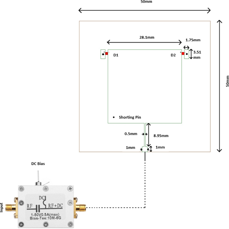
Figure 1: Antenna geometry.
Most of the literature utilizes fixed circularly polarized state patch antennas with increased number of switching elements for switching polarization states. This reduces efficiency of the antenna greatly. In this paper, a polarization agile patch with reduced number of switching elements modelled on single layer substrate is designed. The bottom side of the antenna is fully grounded to arrest the undesired back radiation. The antenna is operating at 2.4 GHz ISM band, and its impedance and radiation characteristics are validated through measured results.
II. GEOMETRY OF THE PROPOSED ANTENNA
The geometry of the proposed patch is shown in Fig. 1. The rectangular patch is taken for its simplicity and better control over its dimensions on design performances. Moreover, the geometry is symmetrical and hence avoids undesired frequency shifts between the frequencies between polarizations states, which makes it ideal for biomedical applications. The antenna is modelled on low-cost fire-retardant substrate with permittivity of 4.4 and loss tangent of 0.02. The overall antenna is modelled on single lay substrate having a dimension of 5050 mm with thickness of 1.6 mm. Two parasitic patches are placed on either side of the antenna geometry in order to reconfigure the antenna structure, thereby modifying the surface current distribution over the antenna radiating element. A shorting via is made in the parasitic patch to complete the DC bias path. Two switching diodes are placed between the parasitic element and the radiating element. Upon proper biasing, the diodes bridge the parasitic element with radiating patch and thereby makes the path for the surface current to flow through parasitic elements, which leads to additional phases for achieving different polarization reconfiguration.
The feed position is chosen in such a way that it matches the impedance of the radiating element by means of using a quarter-wave transformer between the radiating elements and the feed point.
III. PRINCIPLE OF OPERATION
Polarization reconfiguration is achieved by properly biasing the pin diodes (NXP BAP50-03, 50 mA, 50 V). The resistance of the diodes during its operation plays a crucial role in the radiation efficiency of the antenna. The pin diodes are chosen in such a way that it must have a minimum forward resistance during ON condition. The pin diodes used in the model will have a series resistance and inductance of 5 and 1.8 nH during ON state and shunt capacitance 0.35 pF with the reverse resistance of 500 k during OFF state. The equivalent circuit model of the pin diode used is given in Fig. 2. Figures 2 (a), (b) show the diode equivalent circuit model during ON and OFF state. Figure 2 (c) shows the equivalent circuit corresponding to the biasing circuit. It comprises a DC block capacitor and RF choke inductor for isolating the bias network from the antenna elements and hence avoids directcoupling.
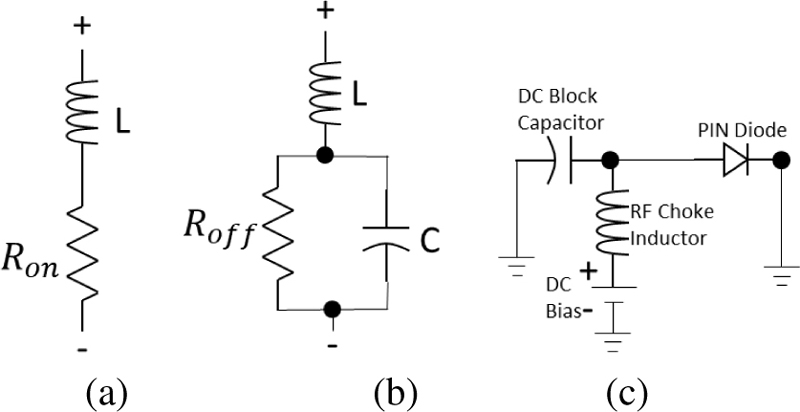
Figure 2: Equivalent circuit model of the pin diode and biasing circuit.
The diodes are placed in such a way that the cathode of the diode D1 points towards the radiating patch while the anode points towards the parasitic patch, which has shorting vias with the ground for the DC path. Similarly, the anode of the diode D2 points towards the radiating patch while the cathode points towards the parasitic patch, which has shorting vias with the ground for the DC path. A Tee- Bias network is used for properly biasing the pin diodes to achieve polarization reconfiguration. Table 1 shows the different operating modes of the proposed antenna model.
Table 1: Different operating modes
| S. No. | DC Bias Voltage | Diode D1 | Diode D2 | Polarization State |
| 1 | 0 V | OFF | OFF | LP |
| 2 | +2 V | OFF | ON | RHCP |
| 3 | -2 V | ON | OFF | LHCP |
When no bias voltage (0 V) is given, both diodes are in OFF state, and the geometry resembles a simple rectangular patch antenna and gives a linear polarization state that resonates at center frequency. When DC bias voltage of +2 V is given, diode D2 turns into ON state as the anode of the diode D2 points towards the radiating patch while the cathode points towards the parasitic patch, which has shorting vias with the ground and hence closes the DC path. Thus, the length of the patch in the right symmetry increases slightly, which introduces additional phase shift between the electric currents (. This generates two orthogonal modes with same amplitude with phase difference and hence attains right-hand circularpolarization.
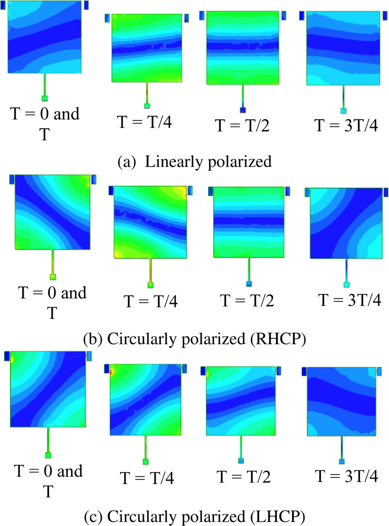
Figure 3: Surface current distribution.
Similarly, when DC bias voltage of -2 V is given, diode D1 turns into ON state as the cathode of the diode D2 points towards the radiating patch while the cathode points towards the parasitic patch, which has shorting vias with the ground and hence closes the DC path. Thus, the length of the patch in the left symmetry increases slightly, which introduces additional phase shift between the electric currents (. This generates two orthogonal modes with the same amplitude with phase difference and hence attains left-hand circular polarization. The surface current distribution corresponding to different polarization states are shown in Fig. 3.
IV. RESULTS AND DISCUSSION
The performance of the proposed antenna is validated by measuring its impedance and its radiation characteristics. The antennas are fabricated on FR4 substrate and are connected with 50 SMA connector, as shown in Fig. 4. The diodes are placed to bridge the radiating patch with the outer parasitic elements. A standard T bias switch is coupled with SMA connector input for biasing the RF switch to switch its polarization characteristics. The shorting pin is punched at its radiating patch center for providing a DC path during biasing of the diodes.
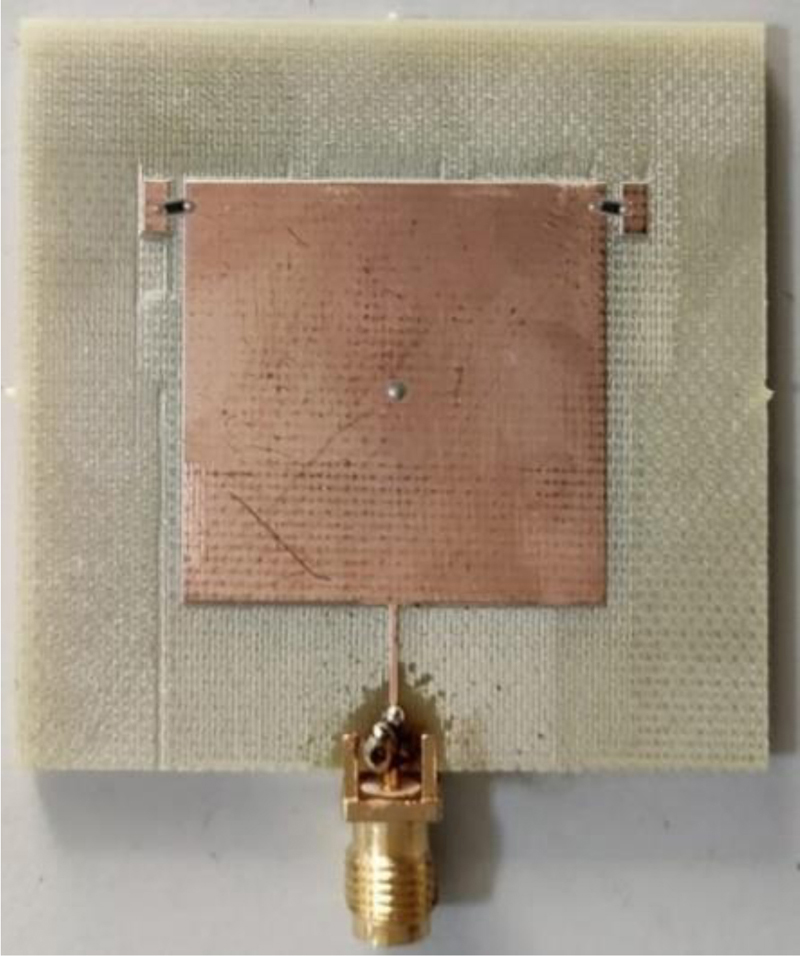
Figure 4: Fabricated prototype.
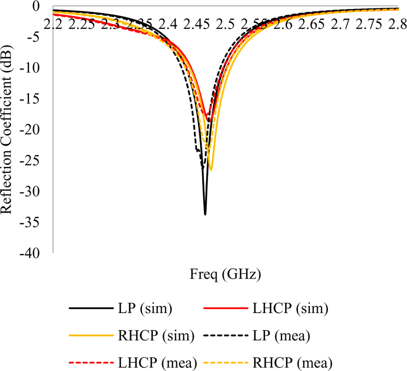
Figure 5: Reflection Coefficient (dB).
The impedance characteristics are measured with Agilent network analyzer (N9925A) and are compared with simulated results, as shown in Fig. 5. From Fig. 5 it is inferred that the antenna attains a 10 dB impedance bandwidth of 100 MHz (2.40-2.5 GHz) in linear state and 85 MHz (2.41-2.495 GHz) in the circularly polarization states respectively.
The radiation measurement setup used to analyze the radiation characteristics of the antenna is shown in Fig. 6.
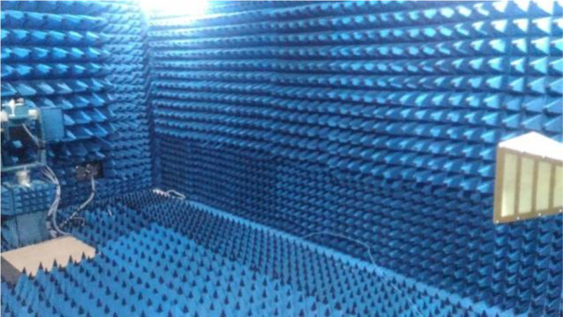
Figure 6: Measurement setup environment for test antenna.
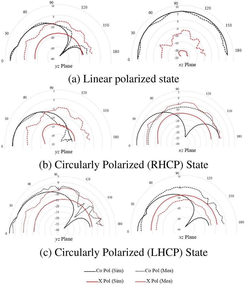
Figure 7: Radiation characteristics of the proposed antenna.
Figure 7 shows the radiation characteristics of the antenna, which are measured using an antenna test system that comprises a pyramidal horn antenna having a standard gain of 9 dB placed inside the anechoic chamber. The test antenna is placed at a far-field distance of from the transmitter antenna, and the gain of the test is calculated based on the Friis transmission equation:
| (1) |
The relative gain corresponding to the fabricated prototype is measured for both the planes. The antenna attains symmetrical radiation pattern in the direction of propagation. The antenna attains maximum gain of 5.61 dBi for the LP state and 4.98 dBi for the LHCP/RHCP state.
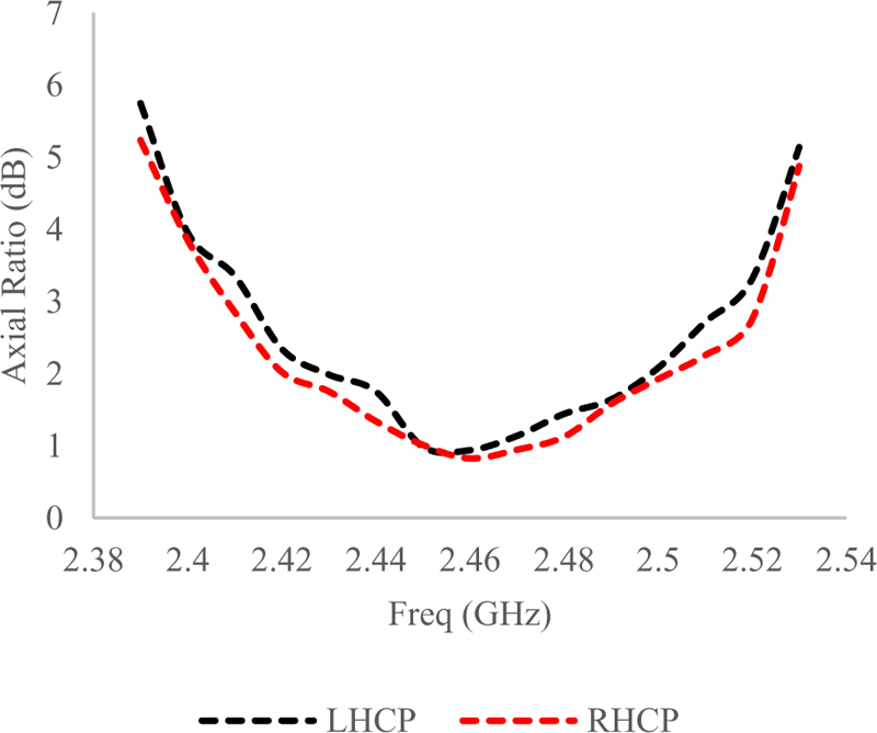
Figure 8: Axial ratio bandwidth of the proposed antenna.
The axial ratio bandwidth corresponding to the proposed model for LHCP and RHCP modes is given Fig. 8. It is inferred that compared to impedance bandwidth, the axial ratio bandwidth is lesser, since the tangential components of the electric fields are attenuated closed to the ground surface. The model attains axial ratio bandwidth of 2.42-2.51 GHz in the operating band.
Specific absorption rate (SAR) is used to quantify the electromagnetic radiation over human tissues, and SAR is calculated by
| (2) |
where and are thermal conductivity, mass density of the tissue medium, and E is the electric field intensity , which is calculated from the power input using the relation given here:
| (3) |
An agar based homogenous tissue model is prepared to mimic human tissue (palm) having a permittivity of 26.47 [12] to measure the SAR value of the proposed model. The model achieves a minimum SAR value of 0.385 at its operating bands.
Table 2: Performance comparison of the proposed antenna
| Ref | Size | Operating Freq. | Polarization | Axial Ratio Bandwidth | SAR (W/kg) |
| [13] | 25 20 0.07 | 2.45 GHz | Linear | 1.22% | 1.0 |
| [14] | 14 14 05 | 2.45 GHz | Circular | 6.93% | 0.494 |
| [15] | 24 22 0.7 | 2.45 GHz | Linear | 24.4% | 0.719 |
| [16] | 21 13.5 0.254 | 2.45 GHz | Circular | 53.8% | 0.78 |
| Proposed | 50 50 1.6 | 2.45 GHz | Circular | 44.8% | 0.385 |
Performance comparison of the proposed model with other conventional models is given in Table 2. Most of the traditional antennas utilize linear polarization or fixed circular polarization techniques, which limits their application. The proposed model utilizes reconfigurable polarization characteristics with a minimum number of electronically controlled switching diodes without sacrificing the impedance and radiation characteristics of the antenna in its operating band. In addition to that, the antenna attains minimum SAR value at the operating band, which makes it suitable for biomedical applications.
V. CONCLUSION
A polarization reconfigurable antenna based on switching pin diodes is presented. The antenna is designed at the 2.45 GHZ ISM band and attains three different polarization states upon proper biasing of the switching diodes. The model is validated by fabricating on single FR4 substrate, and the measured results are compared with simulated results. The antenna achieves -10 dB impedance bandwidth of 100 MHz (2.40-2.5 GHz) in linear state and 85 MHz (2.41-2.495 GHz) in the circularly polarization states along with a peak gain of 5.61 dBi for LP state and 4.98 dBi for CP state in the operating range. The antenna attains maximum axial ratio bandwidth of 44.8% in the operating band with a SAR value of 0.385 W/kg.
ACKNOWLEDGMENT
The work is funded under SEED Grant No.: VTU SEED (FY 22-23) -18 provided by Vel Tech Rangarajan Dr. Sagunthala R&D Institute of Science and Technology, Chennai, India.
REFERENCES
[1] Z. Xia, H. Li, Z. Lee, S. Xiao, W. Shao, X. Ding, and X. Yang, “A Wideband circularly polarized implantable patch antenna for ISM band biomedical applications,” IEEE Transactions on Antennas and Propagation, vol. 68, no. 3, pp. 2399-2404, Mar. 2020. doi: 10.1109/TAP.2019.2944538.
[2] C. Liu, Y. Guo, and S. Xiao, “Capacitively loaded circularly polarized implantable patch antenna for ISM band biomedical applications,” IEEE Transactions on Antennas and Propagation, vol. 62, no. 5, pp. 2407-2417, May 2014. doi: 10.1109/TAP.2014.2307341.
[3] Z. H. Jiang and D. H. Werner, “A compact, wideband circularly polarized co-designed filtering antenna and its application for wearable devices with low SAR,” IEEE Transactions on Antennas and Propagation, vol. 63, no. 9, pp. 3808-3818, Sep. 2015. doi: 10.1109/TAP.2015.2452942.
[4] A. Iqbal, A. Smida, A. J. Alazemi, M. I. Waly, N. Khaddaj Mallat, and S. Kim, “Wideband circularly polarized MIMO antenna for high data wearable biotelemetric devices,” IEEE Access, vol. 8, pp. 17935-17944, 2020. doi: 10.1109/ACCESS.2020.2967397.
[5] K. Kaboutari and V. Hosseini, “A compact 4-element printed planar MIMO antenna system with isolation enhancement for ISM band operation,” AEU - International Journal of Electronics and Communications, vol. 134, ID: 153687, 2021. doi: 10.1016/j.aeue.2021.153687.
[6] M. A. B. Abbasi, S. S. Nikolaou, M. A. Antoniades, M. Nikolić Stevanović, and P. Vryonides, “Compact EBG-backed planar monopole for BAN wearable applications,” IEEE Transactions on Antennas and Propagation, vol. 65, no. 2, pp. 453-463, Feb. 2017. doi: 10.1109/TAP.2016.2635588.
[7] Y. Chen and T. Ku, “A low-profile wearable antenna using a miniature high impedance surface for smartwatch applications,” IEEE Antennas and Wireless Propagation Letters, vol. 15, pp. 1144-1147, 2016. doi: 10.1109/LAWP.2015.2496366.
[8] Z. H. Jiang, M. D. Gregory, and D. H. Werner, “Design and experimental investigation of a compact circularly polarized integrated filtering antenna for wearable biotelemetric devices,” IEEE Transactions on Biomedical Circuits and Systems, vol. 10, no. 2, pp. 328-338, Apr. 2016. doi: 10.1109/TBCAS.2015.2438551.
[9] A. Basir and H. Yoo, “A stable impedance-matched ultrawideband antenna system mitigating detuning effects for multiple biotelemetric applications,” IEEE Transactions on Antennas and Propagation, vol. 67, no. 5, pp. 3416-3421, May 2019. doi: 10.1109/TAP.2019.2905891.
[10] M. Saravanan and M. J. S. Rangachar, “Circular ring-shaped polarization reconfigurable antenna for wireless communications,” Progress In Electromagnetics Research M, vol. 74, pp. 105-113, 2018. doi:10.2528/PIERM18081608.
[11] A. Priya, S. K. Mohideen, and M. Saravanan, “Design of polarization reconfigurable patch antenna for wireless communications,” Applied Computational Electromagnetics Society (ACES) Journal, vol. 35, no. 8, pp. 893-893, 2020.
[12] D. K. Ghodgaonkar, O. P. Gandhi, and M. F. Iskander, “Complex permittivity of human skin in vivo in the frequency band 26.5-60 GHz,” IEEE Antennas and Propagation Society International Symposium. Transmitting Waves of Progress to the Next Millennium. 2000 Digest, vol. 2, pp. 1100-1103,2002.
[13] K. Kumar Naik, S. Chaithanya Teja, B. V. Sailaja, and P. Amala Sri, “Design of flexible parasitic element patch antenna for biomedical application,” Progress in Electromagnetics Research M, vol. 94, pp. 143-153, 2020.
[14] G. V. Kumar and T. Deepali, “Design and performance analysis of a CPW-fed circularly polarized implantable antenna for 2.45 GHz ISM band,” Microwave and Optical Technology Letters, vol. 62, no. 12, pp. 3952-3959, 2020.
[15] K. Kumar Naik, G. Dattatreya, and S. Sandhya Rani, “In-vitro test of miniaturized CPW fed implantable conformal patch antenna at ISM band for biomedical applications,” IEEE Access, vol. 7, pp. 43547-43554, 2019.
[16] A. D. Butt, J. Khan, S. Ahmad, A. Ghaffar, A. J. Abdullah Al-Gburi, and M. Hussein, “Single-fed broadband CPW-fed circularly polarized implantable antenna for sensing medical applications,” PLoS ONE, vol. 18, no. 4, e0280042, 2023.
BIOGRAPHIES

Saravanan Manavalan received his master of engineering degree (comm. system) from Anna Univ., Coimbatore, India in 2012. He did his Ph.D. degree in electronics and comm. engineering at the Hindustan University, India. He had 2 years of teaching experience and more than 5 years of research experience in the field of antennas. Currently he is working as assistant professor at Vel tech University. His area of research includes reconfigurable antennas, metamaterials, and SIW based antennas.

Balraj Shankarlal received his Ph.D. degree in electronics and comm. engineering at Annamalai University, Chidambaram, India. His area of research includes digital image processing.

Veeraswamy Radhakrishnan Prakash faculty in the Department of Electronics and Comm. Engineering, in Hindustan Institute of Technology and science, Chennai, India. His major research work is on video processing and real time image processing. He is an active IEEE member and has published papers in Scopus and Web of science.

Sathish Eswaramoorthy received Ph.D. degree in electronics and comm. engineering at National Institute of Technology, Tiruchirappalli. Currently he is working as assistant professor at Vellore Institute of Technology, India.

Rajmohan Madasamy received his B.E. degree in electronics and comm. engineering from Govt. College of Engineering, Tirunelveli, in 2001. He obtained his M.Tech. degree in VLSI from Dr. M.G.R. Educational and Research Institute, Chennai, in 2005. He obtained his Ph.D. in software defined radio from Hindustan Institute of Technology and Science, Chennai, in 2021. He has around 2 years of industry experience and 14 years of teaching experience. Currently he is an assistant professor in the department of Electronics and Communication Engineering at Hindustan Institute of Technology and Science, Chennai. His research interests include digital circuits and logic design, reversible logic and synthesis, and software defined radio.
ACES JOURNAL, Vol. 39, No. 1, 57–63
doi: 10.13052/2024.ACES.J.390108
© 2024 River Publishers