THz Microstrip Antenna for Terabit Wireless Local Area Networks
V. Koushick, C. Divya, M. Vinoth, E. A. Mohamed Ali, and M. Sugadev
1Department of Electronics & Communication Engineering
Vel Tech Rangarajan Dr. Sagunthala R&D Institute of Science and Technology, Avadi, Chennai, Tamilnadu
koushickvenkat@gmail.com
2Centre for Information Technology & Engineering
Manonmaniam Sundaranar University, Tirunelveli, Tamilnadu
cdivyame@gmail.com
3Department of Electronics & Communication Engineering
K. Ramakrishnan College of Engineering, Samayapuram, Trichy, Tamilnadu
vinothmecs@outlook.com
4Department of Electronics & Communication Engineering
JP College of Engineering, Tenkasi
mummarabi2011@gmail.com
5Department of Electronics & Communication Engineering
Sathyabama Institute of Science and Technology, Chennai
Sugadev74@gmail.com
Submitted On: June 23, 2022; Accepted On: February 23, 2023
ABSTRACT
In order to replace millimetre wave communication for extremely fast terabit wireless local and personal area network connectivity, researchers have been looking into the possibilities of the terahertz band for establishing wireless data communication at terabit rates. The IEEE 802.15 WPAN Terahertz Interest Group (IGTHz) has been created to encourage research in the terahertz bands and set standards for their use, in order to facilitate progress and advancement in this area. The specific objective of this study is to design and analyze a microstrip antenna working at 3.5 THz resonant frequency. The proposed novel antenna includes three layers: a top layer that represents the patch, a second layer that represents the substrate, and a bottom layer that represents the ground plane. It is designed using a 32 nm thin FR-4 substrate with a permittivity of 4.4. Using HFSS simulations, it was found that the proposed antenna has an overall efficiency greater than 85% within the working frequency range of 3.5 THz. Additionally, it exhibited an extremely low reflection coefficient (S) of -43.61 dB at 3.5 THz, with an efficiency exceeding 80%. This simple and broadband antenna design could have relevance in high-speed data transmission networks.
Index Terms: Microstrip patch antenna, multilayer technique, terahertz frequency band, THz antenna.
I. INTRODUCTION
Over the past few years, the manner in which individuals consume, exchange, and generate information has changed, leading to significant growth in wireless data traffic. This has led to an increasing demand for faster wireless connections that can be used anytime, anywhere. Over the last 30 years, the speed of wireless data has increased twofold every 18 months, and it is now reaching the point where it can match the capacity of conventional communication networks. If present trends persist, it is anticipated that wireless networks capable of transmitting terabits of data per second (Tbps) will be present in the next 10 years [1]. Nevertheless, to cope with such exceedingly high data rates, innovative physical layer technologies and novel spectral bands will be needed [2].
“Terahertz (THz) communication” and “sub-THz communication” relate to the usage of frequencies falling within the ranges of 0.1-10 THz and 0.1-0.3 THz [1]. As a result of the need for rapid data transmission over short distances, these frequency ranges have become increasingly important. The terahertz spectrum is capable of transmitting data at high speeds within a range of 10 metres, making it useful for tiny cell cellular networks. Terahertz communication has the ability to be utilized by both stationary and mobile users, as well as in indoor and outdoor settings. Terabit wireless LAN (T-WLAN) offers a way to connect personal computers and tablets to high-speed fiber optic connections. Both cable and wireless channels move data at the same speed in THz communication [2]. Despite the advantages of THz frequencies, communication at these frequencies is challenged by high path loss, which places a severe constraint on communication durations. Further challenges involved in developing dense, high-power transceivers that operate in the THz band include effective radiators that work across an ultra-broadband of THz frequencies, characterizing frequency-selective route loss in the THz band channel, and devising new modulations, transmission strategies and communication protocols that are optimized for the unique features of this band. The THz spectrum is currently unregulated due to these challenges and because many of them are also shared by millimetre wave (mmW) communication systems [3]. However, the radiator size can be decreased to less than a millimetre, which is a huge benefit of THz and sub-THzfrequencies.
Recent advancements in photonic and semiconductor devices have led to the realization of systems operating at Terahertz (THz) frequencies. In such systems, antennas are often fabricated on small substrates before being integrated with active components. However, the integration of on-chip radiators with lossy substrates results in lower efficiency. To address this issue, substrate integration technology has been proposed as a solution, which involves transforming nonplanar antenna designs into planar forms.
While research into achieving Tbps data rates is still in the initial stages, THz communication has the capability of achieving data rates in the Gbps range [4]. Some studies have suggested that polarization multiplexing could be used to achieve Tbps data rates [5]. A newly proposed frequency range in the electromagnetic wave spectrum of THz, which lies between microwaves and infrared light, could enhance data transmission rates [6].
After the ITU World Radiocommunication Conference in 2019, where the frequency band of 275-450 GHz was designated for fixed and land mobile services, researchers have become more interested in THz wireless communication technology. The frequency range of THz waves is defined by the IEEE standard as 0.3-10 THz [7], with a corresponding wavelength range of 0.03-3 mm. These electromagnetic waves have a frequency band of 0.1-10 THz. The THz wave exhibits the following remarkable characteristics:
A. Low damage
Compared to X-rays, THz waves have a lower single photon energy by approximately one part in a million. Consequently, THz waves do not pose a threat to living organisms and can be used for various biomedical applications, such as body scanning for skin cancer, to aid in medical treatment [8].
B. High spectral resolution
Several important compounds have their spectra in the THz range, and analyzing the THz radiation spectrum is necessary to detect harmful objects such as viruses, toxins, and grenades, among others [9].
C. Visualization
Due to their short wavelengths, THz waves can penetrate through different non-metallic or non-polar materials. They can also be converted from opaque to visible opaque objects by THz wave scanning, which can provide higher-resolution images. As a result, THz waves have a significant potential for use in sensing applications, including typical full-body scanners atairports.
D. Wide bandwidth
A THz wave is the electromagnetic wave with the broadest frequency range in electronics. Using THz waves as the signal carrier can significantly increase the speed of information transmission, potentially up to Tbps. The field of THz wave sensing applications has advanced rapidly, but THz antenna applications are not yet fully developed. Due to the limited availability of spectrum resources, antennas are being constructed at higher frequency bands. Compared to typical antennas, THz band antennas provide much higher bandwidth, owing to the broadband performance of the THz spectrum. THz waves offer several advantages over millimetre and light waves, including a wider effective frequency band, stronger beam direction, improved secrecy, and anti-interference performance. THz waves are also more efficient and can penetrate deeper than lightwaves [11].
The broad operational bandwidth of THz antennas is a result of the distinct features of THz waves and plays a crucial role in maximizing performance. The development of THz antennas is required for the usage of THz waves in wireless networks. The operating bandwidth and antenna gain of the system are both directly impacted by the performance of these antennas. The throughput, imaging resolution, and detecting capacities of the system are also highly related to how THz antennas perform. Due to the special characteristics of THz waves, such as their wideband spectrum, high precision, remarkable directivity, and low cost, THz antennas have a variety of benefits. However, designing THz antennas is challenging due to the limitations of materials and manufacturing techniques that restrict the size of THz antennas. Additionally, THz antennas face additional difficulties compared to microwave antennas, such as establishing successful radiating techniques [12]. When it comes to THz antennas, stricter requirements must be followed for the type of antenna, materials used, and manufacturing techniques employed. Sophisticated microfabrication methods, such as slot array, reflector, horn, dipole, and leaky wave antennas, are used to design THz antennas. For sub-THz systems, compact form factor, high gain, and wide bandwidth designs arepreferred.
Previous research has reported several methods for reducing link noise, including a multilayer rectangular cavity design on an InP substrate. This design produced a broad impedance bandwidth of 38 GHz at 300 GHz with only 4 dBi gain [13]. Another study utilized CMOS on-chip technology to create a microstrip patch antenna with four resonators on top. This method resulted in a broadband sub-THz antenna with a central frequency of 10% fractional bandwidth and 15% radiation efficiency [14]. However, both studies faced challenges with antenna size and trade-offs between bandwidth, gain, and structure complexity.
The challenges in developing sub-THz antennas arise from the high precision required during manufacturing and measuring. Despite the existence of numerous techniques for constructing sub-THz antennas at 300 GHz, obtaining high gains, wide bandwidths, and complex structures remains challenging. To tackle this issue, the authors propose an antenna design strategy that achieves high gains and wide bandwidth at sub-THz frequencies. Their approach involves a dipole-based single-element design with significantly increased bandwidth and adequate gain. The authors plan to incorporate alternative radiating directors and array designs to enhance the structure’s gain, while still maintaining its compact form and wide bandwidth.
II. NUMERICAL ANALYSIS
The authors were not able to access the expensive equipment required to fabricate and test THz antennas at such high frequencies when this study was conducted. Even with the adoption of specific methods, such as batch processing, the fabrication of a highly efficient coupling port between the source and the antenna is still challenging, especially for thin substrates. Therefore, the authors employed numerical analysis to validate the antenna’s performance. As a result of its availability and lower cost, FR4 was selected as the substrate for the designed antenna.
The increasing amount of mobile traffic, projected to reach 327 petabytes by 2015, highlights the need for practical and high-speed wireless networks. As the ITU has not allocated frequencies above 275 GHz for any specific purpose, the THz frequency band is a promising option for high-speed communication. Although still in its early stages, THz communication technology has a promising future [15], as demonstrated by the hypothetical wireless personal area network design with THz connections proposed by the U.S. Federal Communications Commission (Fig. 2) and the secure military wireless THz communication network depicted in Fig. 1. Increasing carrier frequencies has been the primary approach to achieve higher data rates, with rates of 10-100 Gbps translating to frequencies of around 100-500 GHz [16]. Additionally, using frequencies over 300 GHz results in smaller antenna sizes that are sub-millimetre in scale.
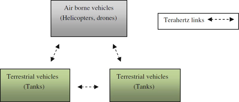
Figure 1: Wireless THz communication network.
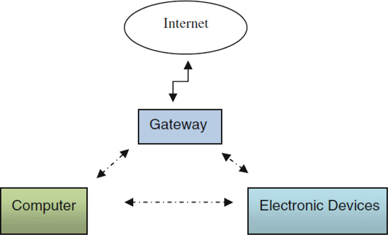
Figure 2: WPAN design with THz connections.
Due to recent advancements in photonic and semiconductor technology, it is now possible to deploy terahertz-based systems. The development of Si-based VLSI control systems, MEMS-based devices, and metamaterials for antennas are essential for THz communications [17]. A high-frequency photodiode capable of producing frequencies between 300 and 400 GHz was reported in [18], with a frequency-to-output power ratio determined through heterodyning at 1.55 m. This photodiode could transmit error-free data at a rate of 2 Gbps at 300 GHz with a transmitted power of 10 W. It had a 140 GHz bandwidth (ranging from approximately 270 to 410 GHz), a maximum output power of 110 W at 380 GHz, and a photocurrent of 20 mA, which is equivalent to a peak output power of 440 W. These are the features described in the article. Because THz frequencies are highly attenuated by atmospheric conditions, outdoor data transmission is not feasible, making it suitable only for short-range indoor applications [18]. The properties of short-range linkages can be estimated using the Friis formula in Equations (1) and (2) as givenbelow:
| (1) | |||
| (2) |
P stands for received power, P for transmitted power, and G and G, respectively, for the transmitter and receiver antenna gains. The wavelength is represented by , distance by d, and the air attenuation by . The system’s noise figure, noise margin, and bandwidth are NF, M, and B, respectively. The THz band, which is made up of tiny cells in a cellular network, can be used for high-speed data transmission within a 10 m radius. THz communication can be used to serve stationary and moving users both inside and outside. T-WLAN enables fast communication between personal electronics like tablets, laptops, and fiber optic cables. In THz communication, both wireless and wired lines communicate at the same speed, enabling bandwidth-concentrated services like wireless data distribution and excellent video conferencing in small spaces. Additionally, THz communication is ideal for military and defence applications utilizing encrypted communicationnetworks.
Massive antenna arrays are required in the THz band to overcome coverage area limitations and transmission losses due to atmospheric attenuation. This results in narrow antenna beams that decrease the likelihood of eavesdropping. Additionally, multiple spread spectrum techniques can be employed to counteract signal jamming attempts. Consequently, the proposed THz antenna is ideal for high-speed communication networks. A typical microstrip patch antenna (MPA) consists of three layers: the top layer, substrate layer, and ground plane. The rectangular patch is created on the top layer and is supported by the substrate layer in the middle. The operating frequency for the proposed terahertz MPA is 3.5 THz, and the thickness of the microstrip patch layer is usually much smaller than the wavelength. However, in this case, the operating frequency is higher, so the thickness value is very small. Therefore, to avoid the design and production constraints depicted in Fig. 3, the thickness value is increased. The proposed THz microstrip patch antenna uses a flame retardant (FR4) substrate and has a geometric design size of 1800 1800 36 nm. The antenna being suggested has dimensions that are mainly in the nanometre range. Table 1 shows the calculated design parameters. The transmission bandwidth of THz waves is much wider than that of mobile communication, as their frequency range is about 1000 timesgreater.
Numerous research teams and organizations have shown interest in THz technology as a potential solution for achieving high data rates in wireless communication systems [19–21]. Compared to mmW systems, THz systems offer a significantly higher capacity and faster data transfer rate, making it a promising candidate for ultra-high-speed wireless communication. THz communication is mainly used for short-distance terrestrial applications and space communication. Despite the fascination of THz waves in the environment, their high transmission rate and strong secrecy meet current demands. Due to its potential for high-speed data transfer, the THz communication system has garnered the attention of many nations, resulting in numerous studies. THz antennas have progressed rapidly and are available in a variety of shapes, such as dielectric lens photoconductive antennas, planar antennas, bowtie dipoles, pyramid-shaped cavities with dipoles, angle reflector arrays, carbon material-based THz antennas, and many more. Conductive antennas, hydrophobic antennas, and innovative technological antennas based on the material used in their development are the three main types of THz antennas. A dielectric antenna consists of a substrate material and an antenna radiator, achieving impedance matching with the detector through proper design and providing a simple, easy integration, and low-costapproach.
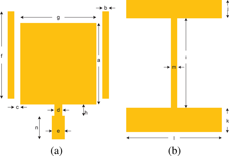
Figure 3: Proposed 3.5 THz MPA structure: (a) radiating layer, (b) bottom layer.
Table 1: Size of the proposed MPA
| Dimensional Parameter | Dimension | Description |
|---|---|---|
| a | 1100 nm | Width of the patch |
| b | 200 nm | Width of parasitic patch |
| c | 150 nm | Gap between active patch and parasitic patch |
| d | 200 nm | Width of feedline |
| e | 300 nm | Width of stub |
| f | 900 nm | Height of parasitic patch |
| g | 700 nm | Length of the patch |
| h | 800 nm | Length of feedline |
| i | 1000 nm | Tapered line of the patch |
| j | 300 nm | |
| k | 500 nm | |
| l | 1800 nm | |
| m | 200 nm | |
| n | 500 nm | Length of stub |
Using the patch antenna cavity model, the following formula can be used to determine the resonant frequency of the propagation modes (TMmn) in the microstrip [22]. The proposed MPA can be designed using equations (3) and (4) as follows:
| (3) | ||||
| (4) |
Theoretically, equation (1), which takes into account the rectangular patch’s dimensions a and b, as well as positive integers m and n, determines the effective relative permittivity (eff). When the dimensions a and b and the permittivity of the substrate layer are known, equation (2) can be used to get the resonant frequency of the dominant mode (TM01). The resonant frequency of TM01 can be altered by adjusting the dimensions a and b of the patch, which allows for higher modes to propagate within the dominant frequency range. In this research, Section 3 describes the design process for determining the values of a and b. The proposed design employs an FR4 substrate layer that measures 1800 1800 36 nm.
The Q-factor of MPA for a given resonant frequency is related as:
| (5) |
The bandwidth is represented by f, the resonant frequency is represented by f, and the Q-factor at the resonant frequency is represented by Q. At the dominant mode of the antenna, the gain and quality factors are related as
| (6) |
where angular frequency, length, and width of the patch and height of the substrate are represented by , , , and , respectively.
Due to higher operating frequency in THz range, the dielectric loss of the antenna is significant and is given by the expression
| (7) |
where is the dielectric attenuation loss in nepers (Np) due to the substrate, is the guide wavelength, and is loss tangent. To reduce the effect of dielectric loss, the thickness of the substrate is kept very small.
The conductor loss of the proposed antenna is expressed as
| (8) |
where is the conducting loss, is the surface resistance, is the characteristic impedance, and is the width of the conducting region in the antenna. To reduce conducting losses, the thickness of the conducting copper layer is kept below 15 m.
III. RESULTS AND DISCUSSION
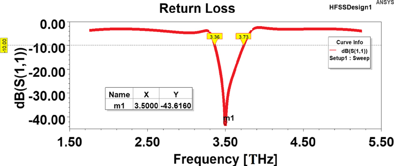
Figure 4: Simulated return loss value at 3.5 THz.
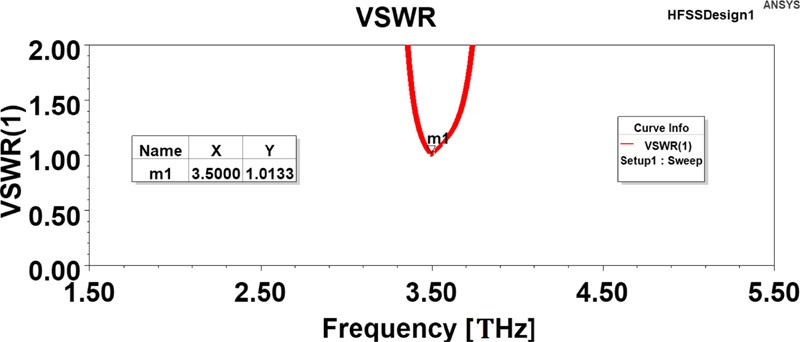
Figure 5: Simulated VSWR value at 3.5 THz.
The proposed THz MPA was simulated in HFSS with a frequency range of 3.5 THz. The simulation results are presented in Fig. 4, showing the plotted S parameters (transmission and reflection coefficients) versus the operating frequency. The simulation indicates a maximum return loss value of approximately -43.61 dB and a voltage standing wave ratio (VSWR) of 1.013, as illustrated in Fig. 5. Based on Fig. 5, the VSWR value is less than 2 in the 3.5 THz working frequency region. The return loss is a function of VSWR [23], which indicates how effectively the radiator is matched to the transmission line or microwave to which it is coupled. A VSWR value between 1 and 2 [22–26] is considered optimal for minimal reflection losses. Antenna values are generally reported with some degree of optimism and accuracy.
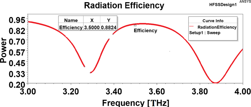
Figure 6: Simulated efficiency value at 3.5 THz.
Table 2: Comparative result analysis
| Ref No | Antenna Structure | Dimensions (mm) | Applications | Frequency (THz) | VSWR | S11 (dB) | Efficiency (%) | Substrate |
| [12] | Multi | 1130 1130 610 | THz comm. | 3 | 1.56 | -27 | - | - |
| [13] | Multi Array | 2550 1217 18 | THz comm. | 3 | - | -23 | - | InP |
| [14] | Multi | 2000 2000 100 | THz comm. | 3 | 1.87 | -10 | - | quartz |
| [30] | Dual Patch | NA | sub-THz radiation detector | 1 | - | -17 | 93.76 | RT-Duroid |
| [34] | Novel Feed Microstrip | NA | NA | 3 | 1.89 | -18 | - | RT-Duroid 5880 |
| [35] | Patch Array Feed Source | NA | THz comm. | 3 | 1.73 | -20 | - | PDMS |
| Proposed | Microstrip Feed | 1800 1800 36 | high-speed comm. | 3.5 | 1.013 | -43.6 | 88.24 | FR4 |
The amount of power given to the radiator doesn’t always get radiated, and matching the antenna with transmission lines is made easier by a low VSWR value. To evaluate the performance of an antenna, the ratio of power sent to a reference antenna compared to that received from an isotropic antenna is used. Most of the power present at the radiator input will be emitted by a high-efficiency radiator. On the other hand, low efficiency causes the majority of the power to be lost within the radiator or reflected due to a mismatched device. The HFSS simulator was used in this study to simulate the proposed THz MPA at a frequency of 3.5 THz. Figure 6 depicts how the simulation results demonstrated that the suggested MPA was successfully radiated in the resonance frequency of 3.5 THz and attained an efficiency of 88.24%. From Fig. 7, the proposed MPA’s impedance is 1.0-0.01 . When compared to current antenna systems, this high efficiency at 3.5 THz performs well [12–14,30, 35].
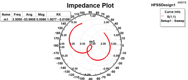
Figure 7: Impedance plot at 3.5 THz.
IV. COMPARISON
This section aims to evaluate and contrast the electrical characteristics of the proposed THz MPA with other high-performance MPAs that have been reported in the literature. Recently, microstrip patch antennas have gained significant attention for their compact size, planar design, and low-cost fabrication, especially for operating at mmW and THz frequencies [12, 13]. In [14], a small-sized MPA for THz applications has been presented. Designing multiband THz antennas has become a new research area, and [30] proposes a dual-band MPA for surveillance systems. [31] suggests a strategy to improve manufacturing tolerance at millimetre and terahertz frequencies by increasing the size of microstrip patches. [34, 35] discusses two innovative ways of feeding microstrip patches and MPA arrays. The electrical characteristics of these MPAs, along with their uses and core values, are summarized in Table 2. The electrical properties of these structures are compared to those of the proposed antenna [38–42].
V. CONCLUSION
The study unveiled a novel, incredibly thin, flexible MPA design that functions at 3.5 THz. The impact of the microstrip patch’s symmetrical structures on its electrical performance was investigated by the researchers. The antenna’s actual performance was in line with the design analysis’s theoretical expectations. The antenna has an exceptionally wide bandwidth for its operational frequency range. Its compact size makes it an attractive option for use in THz applications, especially high-speed communications.
DECLARATIONS
Funding
The authors did not receive any financial support.
Conflicts of interest / competing interests
The authors declare that they have no conflicts of interest or competing interests that could have influenced the conduct or reporting of this research.
Availability of data and material
The datasets and materials used in this study are available upon request to the corresponding author.
Code availability
The custom codes and software applications developed for this research are available upon request to the corresponding author.
Authors’ Contributions
[A.B]: Conceptualization, methodology, and data curation. Designed the study, collected and analyzed the data, and contributed to the interpretation of the results.
[C]: Writing. Original draft preparation and formal analysis. Drafted the initial version of the manuscript and performed statistical analyses.
[D]: Investigation and visualization. Conducted experiments, created figures, and visualized the data.
[E]: Writing. Revision and editing. Revised the manuscript for important intellectual content, grammar, and formatting.
All authors reviewed the manuscript.
REFERENCES
[1] P. H. Siegel, “THz instruments for space,” IEEE Transactions on Antennas and Propagation, vol. 55, no. 11, pp. 2957-2965, [Available]: https://doi.org/10.1109/TAP.2007.908557, 2007.
[2] P. H. Siegel, “Terahertz technology in biology and medicine,” IEEE transactions on microwave theory and techniques, vol. 52, no. 10, pp. 2438-2447, [Available]: https://doi.org/10.1109/TMTT.2004.835916, 2004.
[3] J. Zhang, X. Ge, Q. Li, M. Guizani, and Y. Zhan, “5G millimeter-wave antenna array: Design and challenges,” IEEE Wireless Communications, vol. 24, no. 2, pp. 106-112, [Available]: https://doi.org/10.1109/MWC.2016.1400374RP, 2016.
[4] H. J. Song and T. Nagatsuma, “Present and future of terahertz communications,” IEEE Transactions on Terahertz Science and Technology, vol. 1, no. 1, pp. 256-263, [Available]: https://doi.org/10.1109/TTHZ.2011.2159552, 2011.
[5] T. Nagatsuma, “Advances in terahertz communications accelerated by photonics technologies,” 2019 24th OptoElectronics and Communications Conference (OECC) and 2019 International Conference on Photonics in Switching and Computing (PSC), pp. 1-3, [Available]: https://doi.org/10.23919/PS.2019.8818026, July 2019.
[6] K. Guan, G. Li, T. Kürner, A. F. Molisch, B. Peng, R. He, and A. Zhong, “On millimeter wave and THz mobile radio channel for smart rail mobility,” IEEE Transactions on Vehicular Technology, vol. 66, no. 7, pp. 5658-5674, [Available]: https://doi.org/10.1109/TVT.2016.2624504, 2016.
[7] G. Chen, J. Pei, F. Yang, X. Y. Zhou, Z. L. Sun, and T. J. Cui, “Terahertz-wave imaging system based on backward wave oscillator,” IEEE Transactions on Terahertz Science and Technology, vol. 2, no. 5, pp. 504-512, [Available]: https://doi.org/10.1109/TTHZ.2012.2210282, 2012.
[8] H. Tabata, “Application of terahertz wave technology in the biomedical field,” IEEE Transactions on Terahertz Science and Technology, vol. 5, no. 6, pp. 1146-1153, 2015.
[9] N. V. Petrov, M. S. Kulya, A. N. Tsypkin, V. G. Bespalov, and A. Gorodetsky, “Application of terahertz pulse time-domain holography for phase imaging,” IEEE Transactions on Terahertz Science and Technology, vol. 6, no. 3, pp. 464-472, [Available]: https://doi.org/10.1109/TTHZ.2016.2530938, 2016.
[10] J. Grade, P. Haydon, and D. van der Weide, “Electronic terahertz antennas and probes for spectroscopic detection and diagnostics,” Proceedings of the IEEE, vol. 95, no. 8, pp. 1583-1591, [Available]: https://doi.org/10.1109/JPROC.2007.898900, 2007.
[11] W. Choe and J. Jeong, “Broadband THz CMOS on-chip antenna using stacked resonators,” 2017 IEEE International Symposium on Radio-Frequency Integration Technology (RFIT), pp. 208-210, [Available]: https://doi.org/10.1109/RFIT.2017.8048251, Aug. 2017.
[12] M. Jenning and D. Plettemeier, “Multilayer and multidirectional linearly-tapered slot antenna for 300 GHz applications,” Proceedings of the Fourth European Conference on Antennas and Propagation, pp. 1-5, April 2010.
[13] H. Kanaya, T. Oda, N. Iizasa, and K. Kato, “300 GHz one-sided directional slot array antenna on indium phosphide substrate,” 2015 International Symposium on Antennas and Propagation (ISAP), pp. 1-2, Nov. 2015.
[14] A. Dyck, M. Rösch, A. Tessmann, A. Leuther, M. Kuri, H. Maßler, and O. A. Ambacher, “300 GHz microstrip multilayered antenna on quartz substrate,” 2018 International Workshop on Antenna Technology (iWAT), pp. 1-3, [Available]: https://doi.org/10.1109/IWAT.2018.8379183, Mar. 2018.
[15] H. J. Song and T. Nagatsuma, “Present and future of terahertz communications,” IEEE transactions on terahertz science and technology, vol. 1, no. 1, pp. 256-263, [Available]: https://doi.org/10.1109/TTHZ.2011.2159552, 2011.
[16] K. C. Huang and Z. Wang, “Terahertz terabit wireless communication,” IEEE Microwave Magazine, vol. 12, no. 4, pp. 108-116, [Available]: https://doi.org/10.1109/MMM.2011.940596, 2011.
[17] T. Nagatsuma, H. J. Song, and Y. Kado, “Challenges for ultrahigh speed wireless communications using terahertz waves,” Terahertz Science and Technology, vol. 3, no. 2, pp. 55-65, [Available]: https://doi.org/10.11906/TST.055-065.2010.06.05, 2010.
[18] P. H. Siegel, P. de Maagt, and A. I. Zaghloul, “Antennas for terahertz applications,” 2006 IEEE Antennas and Propagation Society International Symposium, pp. 2383-2386, [Available]: https://doi.org/10.1109/APS,2006.1711074, July 2006.
[19] J. Federici and L. Moeller, “Review of terahertz and subterahertz wireless communications,” Journal of Applied Physics, vol. 107, no. 11, [Available]: https://doi.org/10.1063/1.3386413, 2010.
[20] T. Kleine-Ostmann and T. Nagatsuma, “A review on terahertz communications research,” Journal of Infrared, Millimeter, and Terahertz Waves, vol.32, pp. 143-171, [Available]: https://doi.org/10.1007/s10762-010-9758-1, 2011.
[21] X. Yu, T. Ohira, J. Y. Kim, M. Fujita, and T. Nagatsuma, “Waveguide-input resonant tunnelling diode mixer for THz communications,” Electronics Letters, vol. 56, no. 7, pp. 342-344, [Available]: https://doi.org/10.1049/el.2019.3682, 2020.
[22] J. D. Kraus and R. J. Marhefka, Antennas: For all Applications, third edition, Beijing, China, 2017.
[23] Y. Lo, D. Solomon, and W. Richards, “Theory and experiment on microstrip antennas,” IEEE Transactions on Antennas and Propagation, vol. 27, no. 2, pp. 137-145, [Available]: https://doi.org/10.1109/TAP.1979.1142057, 1979.
[24] T. Kosako, Y. Kadoya, and H. F. Hofmann, “Directional control of light by a nano-optical Yagi–Uda antenna,” Nature Photonics, vol. 4, no. 5, pp. 312-315, [Available]: https://doi.org/10.1038/nphoton.2010.34, 2010.
[25] Constantine A. Balanis, Antenna Theory Analysis and Design, 3rd edition, Wiley India, 2005.
[26] John D Kraus, Antennas, 2nd edition, Tata McGraw Hill Company Limited, 1997.
[27] Pramod Dhande, “Antenna and its Applications,” DRDO Science Spectrum, March 2009.
[28] M. He and X. Xu, “Closed-form solutions for analysis of cylindrically conformal microstrip antennas with arbitrary radii,” IEEE Transactions on Antennas and Propagation, vol. 53, no. 1, pp. 518-525, [Available]: https://doi.org/10.1109/TAP.2004.838772, 2005.
[29] S. S. Kashyap and V. Dwivedi, “Compact microstrip patch antennas for terahertz applications,” 2015 9th Asia Modelling Symposium (AMS), pp. 157-163, [Available]: https://doi.org/10.1109/AMS.2015.33, Sept. 2015.
[30] M. S. Rabbani and H. Ghafouri-Shiraz, “Improvement of microstrip antenna’s bandwidth and fabrication tolerance at terahertz frequency bands,” IET, [Available]: https://doi.org/10.1049/ic.2015.0146, 2015.
[31] P. Kopyt, B. Salski, P. Zagrajek, D. Obrȩbski, and J. Marczewski, “Modeling of silicon-based substrates of patch antennas operating in the sub-THz range,” IEEE Transactions on Terahertz Science and Technology, vol. 7, no. 4, pp. 424-432, [Available]: https://doi.org/10.1109/TTHZ.2017.2706026, 2017.
[32] R. Bhatoa and E. Sidhu, “Novel terahertz microstrip patch antenna design for detection of biotin applications,” 2017 International Conference on Big Data Analytics and Computational Intelligence (ICBDAC), pp. 289-292, [Available]: https://doi.org/10.1109/ICBDACI.2017.8070850, Mar. 2017.
[33] K. R. Jha and G. Singh, “Dual-band rectangular microstrip patch antenna at terahertz frequency for surveillance system,” Journal of Computational Electronics, vol. 9, pp. 31-41, [Available]: https://doi.org/10.1007/s10825-009-0297-8, 2010.
[34] M. S. Rabbani and H. Ghafouri-Shiraz, “Size improvement of rectangular microstrip patch antenna at MM-wave and terahertz frequencies,” Microwave and Optical Technology Letters, vol. 57, no. 11, pp. 2585-2589, [Available]: https://doi.org/10.1002/mop.29400, 2015.
[35] K. R. Jha and S. K. Sharma, “Waveguide integrated Microstrip patch antenna at THz frequency,” 2014 IEEE Antennas and Propagation Society International Symposium (APSURSI), pp. 1851-1852, [Available]: https://doi.org/10.1109/APS.2014.6905252, July 2014.
[36] K. R. Jha and S. K. Sharma, “Waveguide integrated microstrip patch array feed source for a reflector antenna at THz frequency,” 2014 IEEE Antennas and Propagation Society International Symposium (APSURSI), pp. 1465-1466, [Available]: https://doi.org/10.1109/APS.2014.6905058, July 2014.
[37] C. A. Balanis, Modern Antenna Handbook, John Wiley & Sons, 2011.
[38] D. M. Pozar, Microwave Engineering, John Wiley & Sons, 2009.
[39] R. Vallikannu, M. Vinoth, V. Koushick, and E. M. Ali, “A miniaturized defected ground patch antenna for ITS 5G-V2x-C applications,” 2022 International Conference on Computer Communication and Informatics (ICCCI), pp. 1-6, [Available]: https://doi.org/10.1109/ICCCI54379.2022.9741033, Jan. 2022.
[40] C. Divya and V. Koushick, “Design and implementation of slotted metamaterial stacked microstrip patch antenna for broadband applications,” Journal of Physics: Conference Series, IOP Publishing, vol. 1432, no. 1, p. 012067, [Available]: https://doi.org/10.1088/1742-6596/1432/1/012067, 2020.
[41] V. Koushick, C. Divya, and G. Lakshmi, “L/C/X triple band compact dipole array antenna for RADAR application,” Journal of Physics: Conference Series, IOP Publishing, vol. 1432, no. 1, p. 012082, [Available]: https://doi.org/10.1088/1742-6596/1432/1/012082, 2020.
[42] M. Kavitha, T. D. Kumar, A. Gayathri, and V. Koushick, “28GHz printed antenna for 5G communication with improved gain using array,” International Journal of Scientific and Technology Research, vol. 9, no. 3, pp. 5127-5133, 2020.
BIOGRAPHIES

V. Koushick received his B.E degree (ECE) from Anna University Tiruchirappalli in 2011. He received his Post graduate Diploma in VLSI design from Annamalai University Chidambaram in 2011. He received his M.E. degree (communication systems) from Anna University Chennai in 2014. He received his Ph.D., degree (communication systems - information technology (interdisciplinary)) in the field of RF & microwave antennas from Manonmaniam Sundaranar University, Tirunelveli, in 2022. From 2011 to 2012 he worked as lecturer and from 2014 to till date he is working as assistant professor in electronics and communication engineering. Currently, he is working as assistant professor in the Department of Electronics and Communication Engineering at Vel Tech Rangarajan Dr. Sagunthala R&D Institute of Science and Technology, Avadi, Chennai. He published 12 papers in international journals, indexed by UGC CARE List, Scopus, Web of Science, and 9 papers in international conferences organized by IEEE. He received best presenter award from University of Perlis, Malaysia, and best paper award from Ramco Institute of Technology, Virudhunagar, Tamilnadu, sponsored by AICTE, New Delhi. He published 4 Indian patents and 1 German patent. He published 3 book chapter articles and submitted 2 book chapters in Taylor and Francis. He serving as member educationist in Sigma CBSE School, Tiruchirappalli. He is a member in IAENG, IRED, BES, HKCBEES, and INSTICC professional bodies. He is an active reviewer in ACES, IEEE conferences, and reputed journals. His research areas include antennas, RF and microwaves, RADAR and VLSI.

C. Divya received her B.E degree from Anna University Chennai in 2008. She received her M.E. degree from Anna University Chennai in 2010. She received her Ph.D., degree from Manonmaniam Sundaranar University, Tirunelveli, in 2014. From 2010 to date she is an assistant professor in Centre for Information Technology and Engineering, Manonmaniam Sundaranar University, Tirunelveli. She published 14 papers in international journals and 7 papers in international conferences. She published book and chapters in sensor networks and cyber security. She received merit scholarship award from SSN College of Engineering, Chennai. She organized many workshops and seminars funded by UGC. She is an eminent editorial board member and reviewer in various international journals, like RJIOT, JSTEI and IACSIT. She published 2 Indian patents and 1 book chapter. She is an associate member in many professional bodies, like IAENG and UACEE. Her research areas include wireless sensor networks, communication networks, nano devices and low power VLSI.

M. Vinoth received his B.E degree (ECE) from Anna University Tiruchirappalli in 2011. He received his M.E. degree (Communication Systems) from Anna University Chennai in 2015. He received his Ph.D., degree in the field of RF & Microwave Antennas from Hindustan Institute of Technology and Science in 2022. Currently, he is working as Assistant Professor in the Department of Electronics and Communication Engineering at K. Ramakrishnan College of Engineering (Autonomous), Tiruchirappalli. He published 10+ papers in International Journals which is indexed by SCIE, Scopus, Web of Science and 10+ papers in international conference organized by IEEE. He received best paper award from Ramco Institute of Technology, Virudhunagar, Tamilnadu sponsored by AICTE, New Delhi. He published 1 German patent. He has 10 Years of Industrial experience and 3 Years of Teaching experience. His research areas include Antennas, RF and Microwaves, MIMO, 5G Bands Networks etc.,

E. A. Mohamed nobtained his Bachelor degree in Electrical and Electonics Engineering from the Manonmaniam Sundaranar University (India), Tirunelveli in 2000. He then pursued a Master degree in Applied Electronics in 2001 from Madurai Kamaraj University and a Ph.D. from Anna University, Chennai. Currently, he holds the position of Associate Professor in the Department of ECE at JP College of Engineering, Tenkasi. His research interests include Systme Engineering, Image and Signal Processing, RF and Wireless Communications, and he is a member of the ISTE, IETE and IAENG. He has authored more than 50 research publications in international journals and conferences.

M. Sugadev received his Bachelor degree in Electronics and Communication Engineering from Institution of Engineers (India), Kolkatta in 2005, Master Degree in VLSI Design in 2008 and Ph.D. from Sathyabama Institute of Science and Technology, Chennai. He is working as Associate Professor in Department of ECE, at Sathyabama Institute of Science and Technology, Chennai. His areas of research include RF and Wireless Communications. He is a member of Institution of Engineers (India) and IETE. He has more than 50 Research publications in International Journals and Conferences.
ACES JOURNAL, Vol. 38, No. 7, 522–531
doi: 10.13052/2023.ACES.J.380708
© 2023 River Publishers