Investigation and Analysis of Electromagnetic Interference for PWM Encoder of Urban Rail Train
Yang Yang, Feng Zhu, Yuxuan Wang, and Chengpan Yang
1School of Electrical Engineering
Southwest Jiaotong University, Chengdu, 610031, China
280899254@qq.com, zhufeng@swjtu.edu.cn, 864940620@qq.com, yangcook@foxmail.com
2Department of Mechanical and Information Engineering
Sichuan College of Architectural Technology, Deyang, 618000, China
Submitted On: July 4, 2022; Accepted On: September 22, 2023
ABSTRACT
Electromagnetic compatibility (EMC) is an important factor in ensuring the safe operation of the sensitive electronic equipment on urban rail trains. The pulse width modulation (PWM) encoder of an urban rail train exported from China to Brazil is sometimes affected by electromagnetic interference (EMI), which causes the train to fail to run properly. To solve this problem, the EMC test is performed on the PWM encoder to identify the coupling path and the type of interference source. The EMI coupling model and the vehicle-catenary-rail model are established by using an electromagnetic transients program (EMTP) to analyze the mechanism of interference coupling. It is shown that the unbalanced voltage of the train body caused by the backflow of the grounding current is the root cause of the interference of the PWM encoder. The maximum voltage coupled to the internal port of the PWM encoder is about 1894 V, which is sufficient to burn out the encoder. A measure to suppress the interference by installing thyristor surge suppressors (TSS) P0300SC is proposed, which effectively solves the EMI problem of the PWM encoder.
Index Terms: Coupling path, electromagnetic interference (EMI), EMI suppression, pulse width modulation (PWM) encoder, urban rail train.
I. INTRODUCTION
With the advancement of rail transit, the electromagnetic environment is becoming increasingly intricate, and the variety of on-board electronic equipment has expanded significantly. As a crucial component of the train, the dependable operation of on-board control and communication devices such as pulse width modulation (PWM) encoders are paramount to ensuring safe and reliable operation [1, 2].
The PWM encoder is used to control traction and braking of the train, and its internal circuit is shown in Fig. 1 [3]. The optical coupler converts the analog signal, which is input from the driver’s control handle into high and low levels accurately. When the optical coupler output is high , the metal-oxide-semiconductor field-effect transistors (MOSFETs) T and T are in a conducting state, so the PWM encoder outputs a low level. Conversely, when the optical coupler output is low, Tand T cut off and the encoder outputs a high level. The optical coupler controls the conduction and cut-off time of each MOSFET, generating pulse signals with different duty ratios ranging from 10% to 90%. These signals are then fed into the control unit to achieve traction and braking of the train. Due to the differences in train grounding methods and in circuit structures and rail quality in different countries, import/export trains, particularly on-board equipment such as PWM encoders, may be affected by electromagnetic interference (EMI). Therefore, it is of great significance to investigate the EMI caused by changes in train operating environments and to study the solutions.
Currently, some experiences and achievements have been accumulated in the investigation and solution of EMI for train on-board equipment. The authors in [2, 4] analyzed the failure of the speed sensor caused by the overvoltage of the train body and the pantograph-catenary contact-loss arc. They proposed measures to address this issue by changing the grounding system. Moreover, when the pantograph was raised or lowered, the on-board balise transmission module (BTM) is subjected to EMI from the arc, resulting in traction blockade. This fault was resolved by improving the BTM’s immunity as described in [5], and further research on the BTM’s electromagnetic sensitivity is presented in [6]. Reference [7, 8] proposed optimizing wiring and applying cascode level shifter to solve EMI problems related to abnormal LCD displays in the passenger information system. However, there is a lack of research on the EMC of train PWM encoders.
The train EMC problem is mainly related to the railway pantograph-catenary system and grounding system. In terms of research on the interference source model, Guardado et al. [9] improved two black boxes of pantograph-catenary arc models: the Cassie model [10] and the Mayr model [11]. Wei et al. [12] established a grounding reflux model for high-speed electric multiple units (EMUs) with scattered protection grounding, aiming to reduce the voltage of train body and the grounding current. In [13, 14], the vehicle-catenary and vehicle-catenary-viaduct models were respectively built to investigate the train body overvoltage in case of EMU passing neutral section device. The above scholars mainly studied the pantograph-catenary system and the grounding system of high-speed EMU, but there is a lack of research on the EMC of urban rail trains.
There is a problem of PWM encoder burnout during operation in urban rail trains exported from China to Brazil, which have a power supply of 2400 kW and run on DC 3000 V. The specific components that have burned out include resistors R and R, as well as MOSFETs T and T, which are shown in Fig. 1. At present, the interference source, coupling path, coupling mechanism, and solution to this problem have not been studied. In order to solve these problems, we carry out EMC tests and propose a vehicle-catenary-rail coupling model based on EMTP to study the EMI of the PWM encoder.
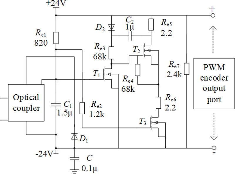
Figure 1: Internal circuit of PWM encoder.
The remainder of the paper is organized as follows. Section II investigates the interference coupling path of the PWM encoder and the types of interference sources through the EMC test. The coupling model is established in Section III to analyze the interference coupling mechanism. The coupling model is verified, and EMI suppression measures are proposed from the perspective of protecting sensitive equipment in Section IV. Section V is the conclusion.
II. INVESTIGATION OF COUPLING PATH AND INTERFERENCE SOURCE
The three elements of electromagnetic interference include interference source, coupling path, and sensitive equipment. In this section, according to the standard IEC 62236 [15], radiated immunity tests, electrostatic discharge (ESD) immunity tests, electrical fast transient/burst (EFT) immunity tests, and surge (SUG) immunity test are carried out to investigate interference sources and coupling paths of the PWM encoder, which is the sensitive equipment.
A. Investigation of coupling path
Electromagnetic coupling can be classified into two types: radiation coupling and conduction coupling. The radiated immunity test is carried out on the PWM encoder as shown in Fig. 2. The radio frequency signal transmitter (HP-8648C) and the log-periodic antenna (DS-3200) are utilized to simulate potential radiation interference sources such as the pantograph-catenary arc on trains mentioned previously.
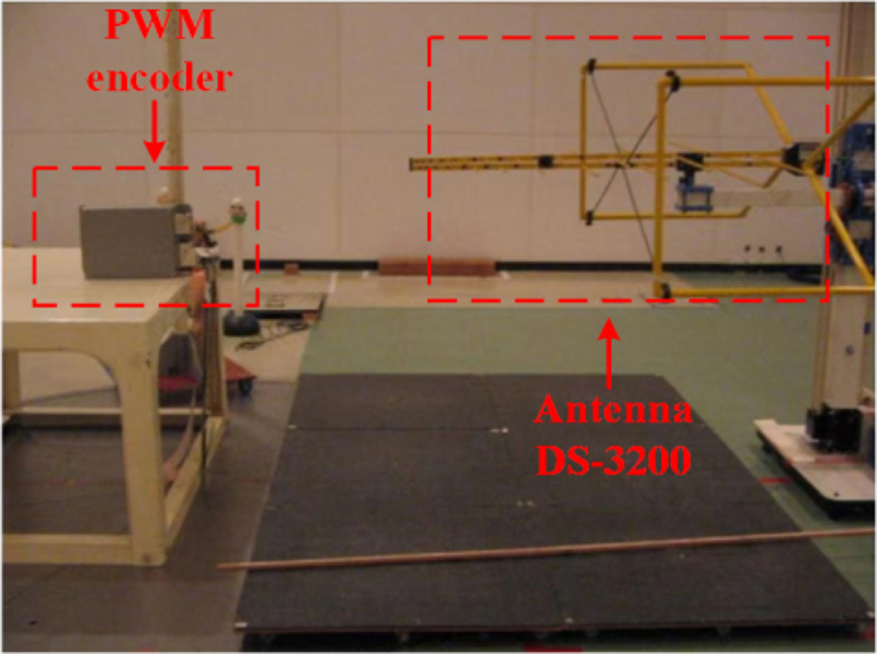
Figure 2: Radiated immunity test on PWM encoder.
Table 1: Radiated immunity results of PWM encoder
| Frequency | Electric FieldIntensity | Test Times | Results |
|---|---|---|---|
| 80 MHz-1 GHz | 20 V/m | 20 | Normal |
| 1.4 GHz-2 GHz | 10 V/m | 20 | Normal |
In this test, vertical and horizontal polarization radiation is carried out on six surfaces of the PWM encoder, respectively. The results are shown in Table 1. It is evident that the encoder can work normally after being exposed to radiation on all six surfaces within the experimental frequency range of 80 MHz-1 GHz with an electric field intensity of 20 V/m and a frequency range of 1.4 GHz-2 GHz with an electric field intensity of 10 V/m.
Moreover, the PWM encoder on the train is tested with the handheld field intensity meter (TES-593) at the work site. The data showed that the maximum electric field intensity in the working environment does not exceed 5 V/m, which indicates that radiation coupling is not responsible for the burnout of the PWM encoder, and therefore the coupling path is conduction coupling.
B. Investigation of interference source type
Conduction coupling tests, including ESD, EFT, and SUG immunity tests, are carried out on the PWM encoder to determine the source of interference.
(1) ESD test
As illustrated in Fig. 3, an ESD generator (ESD61002AG) is selected as the test equipment.
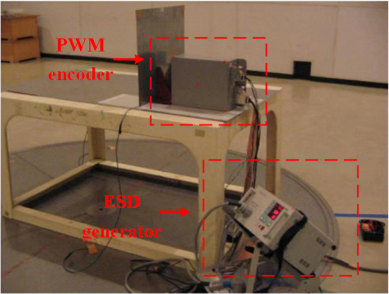
Figure 3: ESD immunity test of PWM encoder.
The results of the ESD test are presented in Table 2, showing that the encoder can still work normally after being subjected to 20 direct and indirect discharges at the voltage level of 4 kV.
Table 2: ESD immunity results of PWM encoder
| Types | Voltage Level | Test Times | Results |
|---|---|---|---|
| Directdischarge | 4 kV | 20 | Normal |
| Indirectdischarge | 4 kV | 20 | Normal |
(2) EFT test
As illustrated in Fig. 4, the EFT generator (EFT61004BG) is selected as the test equipment.

Figure 4: EFT immunity test of PWM encoder.
The results of the EFT test are presented in Table 3, showing that the PWM encoder can still work normally after 20 tests on the power port and signal port of the encoder under a voltage level of 2 kV.
Table 3: PWM encoder EFT immunity results
| Location | Voltage Level | Test Times | Results |
|---|---|---|---|
| Power port | 2 kV | 20 | Normal |
| Signal port | 2 kV | 20 | Normal |
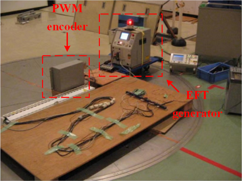
Figure 5: SUG immunity test of PWM encoder.
(3) SUG test
As illustrated in Fig. 5, the SUG generator (SUG61005AG) is selected as the test equipment.
The results of the SUG test are shown in Table 4. The PWM encoder can still work normally after 20 tests on its power port at a voltage level of 2 kV; however, it burned out when the voltage applied to its internal circuit port reached 1.8 kV or higher.
Table 4: PWM encoder SUG immunity results
| Location | VoltageLevel | TestTimes | Results |
|---|---|---|---|
| Power port | 2 kV | 20 | Normal |
| Internal circuit port | 2 kV | 20 | Burned |
| 1.9 kV | 20 | Burned | |
| 1.8 kV | 20 | Burned | |
| 1.7 kV | 20 | Normal |
From the test results, it can be determined that the EMI is not caused by ESD or EFT. The interference source is identified as the SUG voltage from the internal circuit port of the PWM encoder. In addition, an oscilloscope is used to test the output port of the PWM encoder at the operation site of the urban train, as shown in Fig. 6. The actual transient voltage peak value is measured up to 1843 V, which verifies the rationality of the above EMC tests.
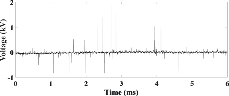
Figure 6: The voltage of encoder output port tested by oscilloscope.
III. COUPLING MECHANISM OF EMI
A. Coupling model of EMI
By performing on-site investigations of the urban train operations in Rio de Janeiro, Brazil, it is found that the majority of the train’s grounding wires are overloaded with current and have become blackened due to the overcurrent. In serious cases, some grounding wires have even been burned off. In addition, the rails are found to be in poor condition, having suffered from severe rusting caused by corrosion from the sea breeze. Even some of the electric connecting wires between the rails are missing, causing the grounding current to fail to return to the traction substation properly. The current acquisition device is used for field testing of the current in each grounding wire of the train. The transient current of the grounding wire is illustrated in Fig. 7, where a positive amplitude indicates that the transient current is flowing into the train body and a negative amplitude indicates that it is flowing out.
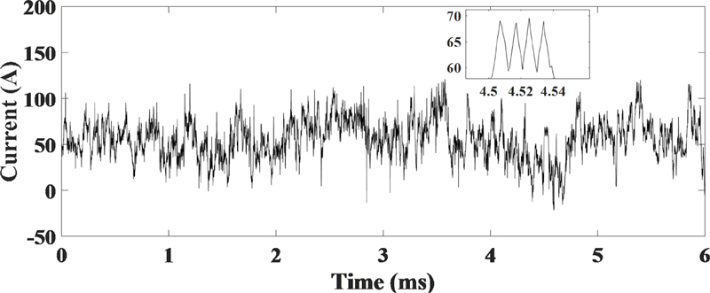
Figure 7: The transient current of grounding wire.
The inflow of transient grounding current into the train body can lead to an excess potential difference in the rails under the train, and can also lead to an unbalanced voltage in the train body due to its own impedance, thereby affecting the onboard electrical equipment. The interconnect cable of the PWM encoder is a two-core symmetric shielded cable whose shielding layer is grounded, that is, connected to the train body. When the unbalanced voltage of the train body is applied to both ends of the shielding layer, it capacitively couples to the inner core wires of the shielded cable and creates a potential difference. This interference voltage is then connected to the internal circuit of the PWM encoder, as demonstrated in Fig. 8. C and C are the equivalent capacitances between the shielding layer and the two inner core wires, and C is the equivalent capacitance between the two inner core wires [16]. R, R, C, and T are the internal components of the PWM encoder in Fig. 1, U is the unbalanced voltage at the two ends of the shielding layer, and U is the interference voltage coupled to the output end of the encoder.
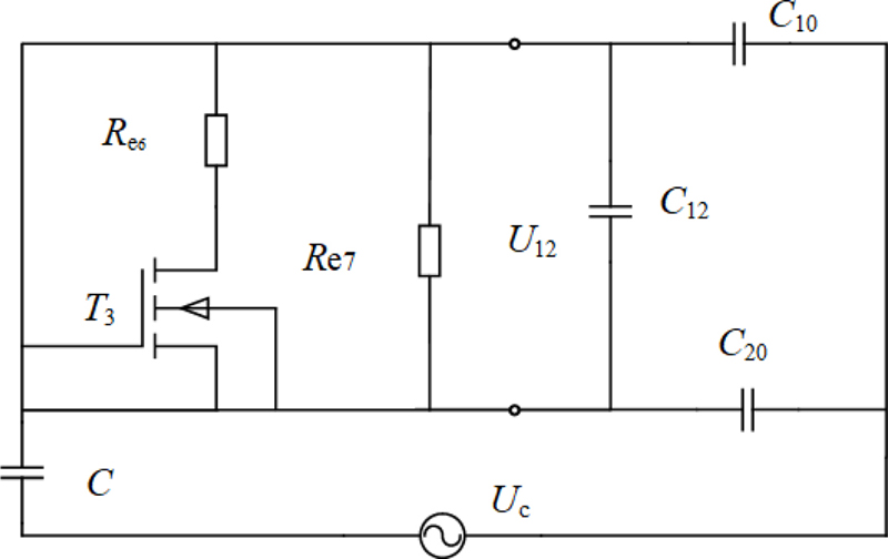
Figure 8: Capacitive coupling model.
B. Calculation of parameters
In order to obtain U and U, it is necessary to calculate the related parameters of rail and train body.
(1) Rail resistance and inductance
It can be seen from the partially enlarged area of Fig. 7 that the transient current here presents a periodic change with a cycle time of 0.01 ms, so the frequency f of the transient current is approximately 100 kHz. At this frequency, the amplitude of the current density in the current-carrying conductor will be attenuated, and the current mainly exists in the thin layer on the surface of the conductor, which is called the skin effect. Specifically,
| (1) |
where is the effect depth, is the conductivity of the rail, and represent vacuum permeability and rail permeability, respectively.
The equivalent section of the rail is shown in Fig. 9 [17], where R’ is the equivalent radius of the rail.
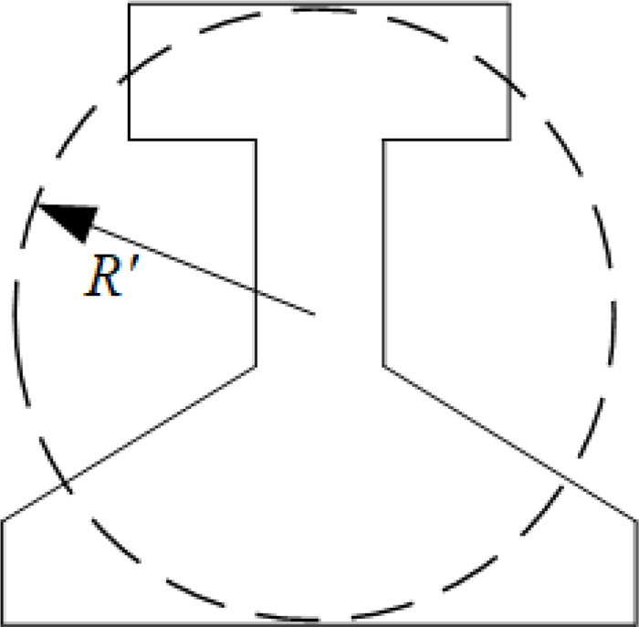
Figure 9: Equivalent section of the rail.
Accounting for skin effect, the rail AC resistance can be mathematically expressed as
| (2) |
| (3) |
where Ris the rail AC resistance considering skin effect, R is the rail DC resistance.
The magnetic flux is divided into inner and outer magnetic flux. When the current is uniformly distributed within the rail conductor, the flux linkage between the current-carrying conductor and the inner magnetic flux is:
| (4) |
where I is the current flowing through theconductor.
However, in the case of a high frequency of 100 kHz, (4) needs to be modified due to the existence of the skin effect. The current density J(r) at the rail radius r can be written as
| (5) |
where J is the rail surface current density.
The total current flowing through the rail is
| (6) |
The current contained at the rail radius r is:
| (7) |
Flux linkage between I and the inner magnetic flux can be deduced as
| (8) |
The internal self-inductance of the rail is
| (9) |
where the coefficient k is
| (10) |
The calculation diagram of flux linkage between outer magnetic flux and current of rail is shown in Fig. 10. The distance between the rail and the catenary denotes D, and the flux linkage between outer magnetic flux and current is
| (11) |
The rail outer self-inductance L is as follows:
| (12) |
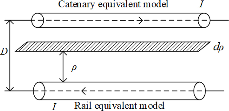
Figure 10: Schematic diagram of flux linkage calculation.
(2) Train body inductance
To calculate the train body inductance, the catenary and the train body can be approximately equivalent to a cylinder and a hollow cylinder with thickness d, respectively, as shown in Fig. 11 [18]. Here, d is the difference between the inner radius r and the outer radius r of the equivalent train body; r is the equivalent radius of the catenary; and d is the distance between the catenary and the train.
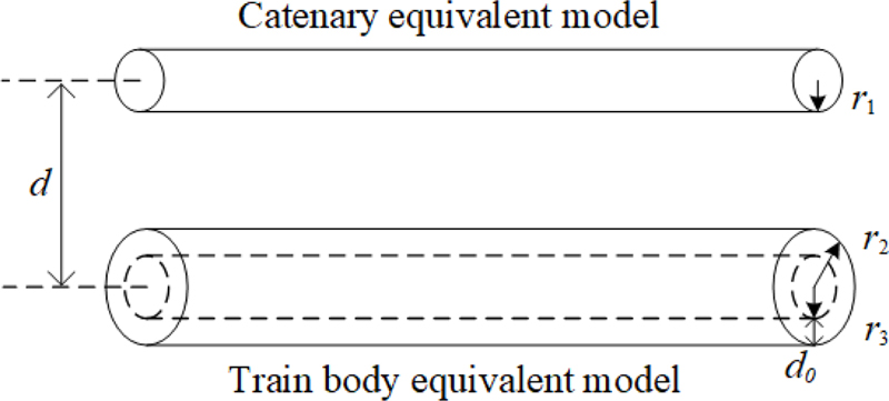
Figure 11: Train body-catenary equivalent model.
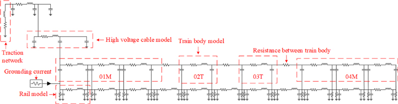
Figure 12: The vehicle-catenary-rail model of urban rail train.
Table 5: Relevant parameters of urban rail train
| Variable | Value | Variable | Value | Variable | Value |
| C/(F) | 0.005611 | D/(m) | 6.5 | High voltage cable inductance/(mH/m) | 0.000131 |
| C/(F) | 0.005611 | r/(m) | 0.01 | High voltage cablecapacitance/(F/m) | 0.000411 |
| C/(F) | 0.001414 | b/(m) | 2.8 | Rail resistance/(m/m) | 5.15 |
| /(H/m) | 410 | h/(m) | 3.8 | Railinductance/(mH/m) | 0.00178 |
| 150 | m/(kg) | 150 | Rail capacitance/(F/m) | 0.000852 | |
| /(H/m) | 410 | /(kg/m) | 2700 | Train bodyresistance/(m/m) | 0.15 |
| /(S/m) | 4.76210 | Traction substation resistance/() | 0.165 | Train bodyinductance/(mH/m) | 0.000473 |
| /(S/m) | 5.810 | Traction substationinductance/(mH) | 10.8 | Train bodycapacitance/(F/m) | 0.0000234 |
| R/(mm) | 109 | High voltagecable resistance/(m/m) | 0.014 | Resistance betweentrain body/(m) | 4 |
In practice, the train body can be approximated as a cuboid with width b and height h, and its per unit length mass and density are m and , respectively. The relationship between these parameters is expressed as follows:
| (13) |
| (14) |
| (15) |
According to relevant self-inductance knowledge and skin effect [19, 20], the train body current will mainly be distributed to the effect depth :
| (16) |
where represents the permeability of train body and denotes its conductivity.
By calculating the inner self-inductance L and outer self-inductance L of the train body, the train body self-inductance L can be obtained as
| (17) |
| (18) |
| (19) |
The vehicle-catenary-rail model of the urban rail train is built based on the EMTP software to calculate the unbalanced voltage of the train body U, which is shown in Fig. 12. The train is composed of two tractors (01M, 04M) and two trailers (02T, 03T). The pantograph is connected to the train body by high-voltage cables, and the train body is connected to the rails by a grounding system. As mentioned in Sec. III, the inflow of transient grounding current into the train body is responsible for U, and the frequency of the transient current is approximately 100 kHz, as shown in Fig. 7. Thus, the AC model is built with the transient grounding current as the source. Relevant parameters can be obtained from on-site measurements, theoretical calculations, and table lookup, as listed in Table 5.
IV. VERIFICATION AND ANALYSIS
This section is divided into two parts, including the correctness of the capacitive coupling model and measures for interference suppression.
A. Verification of coupling model
The transient voltage waveform of the rail obtained by EMTP is shown in Fig. 13, revealing a maximum value of 4867 V. The unbalanced voltage U of the train body is shown in Fig. 14 with a maximum voltage of 3632 V.
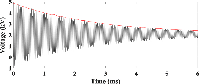
Figure 13: The transient voltage of rail.
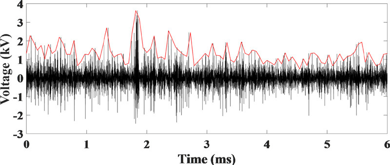
Figure 14: The unbalanced voltage U of train body.
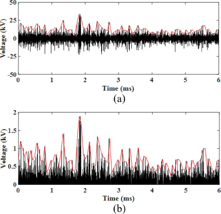
Figure 15: The output port voltage of PWM encoder: (a) low level, (b) high level.
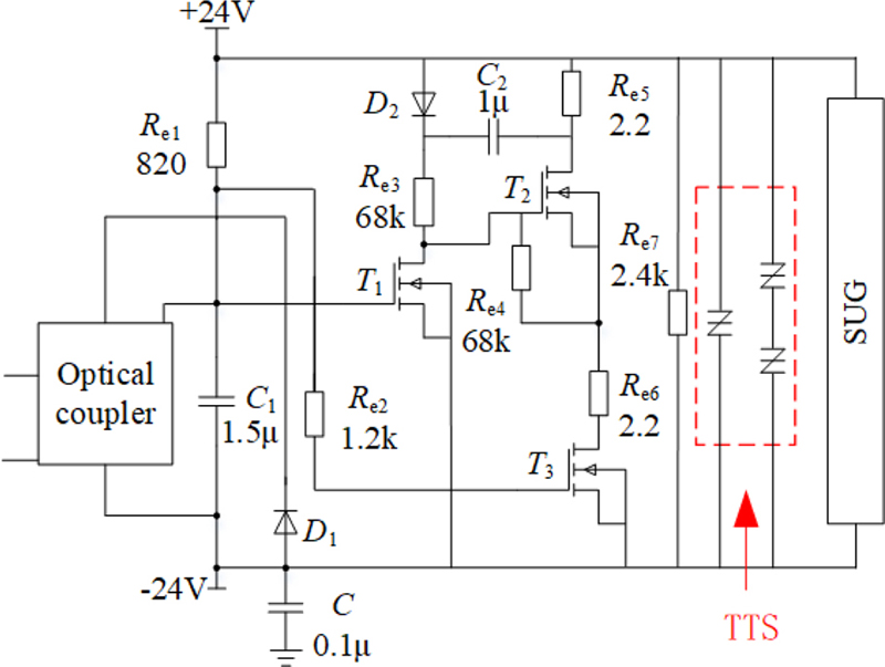
Figure 16: The schematic diagram of installing TSS at PWM encoder output port.
According to the coupling model illustrated in Fig. 8, when T is conducting, its resistance is 0.2 , and the output equivalent resistance R is 2.4 ; otherwise, its resistance is 2.4 k, and the output equivalent resistance R is 2.4 k. The voltage U coupled to the output port in the aforementioned two states can be calculated. As shown in Fig. 15 (a), when the output of the PWM encoder is at a low level, the peak voltage resulting from transient current coupling to the output port can reach up to 33 V. Conversely, when the output is at a high level, as shown in Fig. 15 (b), the maximum peak voltage of the output port reaches 1894 V. Compared to the voltage of the encoder output port, 1843 V, measured by the oscilloscope in Fig. 6, the absolute error between simulated and measured voltage results is small, indicating the soundness of the coupled model and mechanism analysis.
B. EMI suppression measures
Because the PWM encoder and the train are produced and supplied by different companies with different EMC standards, it is easy to cause the resistance and MOSFET to be burned. It can be seen from the SUG test that the PWM encoder needs to be able to withstand higher surge impulse voltages. Therefore, from the perspective of sensitive equipment, enhancing its immunity to suppress EMI can be considered as a solution. The suppression measure involves selecting the thyristor surge suppressors (TSS) P0300SC and installing them between the positive and negative lines of the output port of the PWM encoder. A schematic diagram depicting this arrangement is shown in Fig. 16.
When the PWM encoder is working properly, the TSS is cut off. When the surge transient voltage is coupled and impacts the internal circuit, the TSS will be conducting to discharge the surge current to the ground, thereby protecting the internal components of the encoder.
The SUG test was performed following the internal circuit diagram described above after the TSS was installed, and the results are shown in Table 6. Compared to the original case without the suppression measure, the encoder with TSS can withstand a voltage of up to 3.3 kV and its working state is not affected, which can effectively suppress the EMI. Furthermore, the components are not burned and the train operates normally after putting the encoder with the TSS into the urban rail train.
Table 6: SUG immunity results of PWM encoder with TSS
| Location | Grade | Test Times | Results |
|---|---|---|---|
| Internal circuit port | 1.8 kV | 20 | Normal |
| 3.2 kV | 20 | Normal | |
| 3.3 kV | 20 | Normal | |
| 3.4 kV | 20 | Burned |
V. CONCLUSION
In this paper, EMC tests are conducted to investigate the types of EMI sources and interference coupling paths for the PWM encoder used in urban rail trains in Brazil. A coupling model is then established based on the test data to analyze the interference coupling mechanism of the encoder. It is shown that the unbalanced voltage of the train body is the main cause for the interference of the PWM encoder, which can reach a peak voltage of up to 3632 V. In addition, the unbalanced voltage of the train body will be coupled to the internal port of the PWM encoder via the shielded cable with a coupling voltage of 1894 V, which can cause EMI on the encoder and burn out its components. This voltage value is consistent with the EMC test and measurement data, validating the correctness of the analysis.
Finally, the EMI problem of the PWM encoder has been solved by installing the TSS P0300SC between the positive and negative lines of the output port of the PWM encoder, which increases the interference voltage from 1.8 kV to 3.3 kV.
ACKNOWLEDGMENT
This work is supported by the National Key R&D Program of China (No.2018YFC0809500) and the Science and Technology Project of Sichuan College of Architectural Technology (No.2023KJ05).
REFERENCES
[1] Y. Tang, F. Zhu, and Y. Chen. “Research on the influence of train speed change on the EMI of pantograph-catenary arc to main navigation stations,” Applied Computational Electromagnetics Society (ACES) Journal, vol. 36, no. 4, pp. 450-457, 2021.
[2] Y. Tang, F. Zhu, H. Lu, and X. Li, “Analysis and suppression of EMI for traction control unit speed sensors of CRH380BL electric multiple unit,” Applied Computational Electromagnetics Society (ACES) Journal, vol. 66, no. 5, pp. 553-560, May 2018.
[3] D. S. Jia and S. S. Wang, “Application of PWM encoder based on micro-controller for light rail vehicles,” Electric Locomotives & Mass Transit Vehicles, vol. 31, no. 1, pp. 23-26, Jan. 2008.
[4] K. Huang, Z. Liu, F. Zhu, Z. Zheng, and Y. Cheng, “Evaluation scheme for EMI of train body voltage fluctuation on the BCU speed sensor measurement,” IEEE Transactions on Instrumentation and Measurement, vol. 66, no. 5, pp. 1046-1057, May 2017.
[5] D. Franco, M. Aguado, C. Pinedo, I. Lopez, I. Adin, and J. Mendizabal, “A contribution to safe railway operation: evaluating the effect of electromagnetic disturbances on balise-to-BTM communication in railway control signaling systems,” IEEE Vehicular Technology Magazine, vol. 16, no. 2, pp. 104-112, June 2021.
[6] Y. Wen, Q. Geng, J. Xiao, Y. Zhu, D. Zhang, and P. Spadoni, “Study on the electromagnetic susceptibility of balise transmission module system,” International Conference on Electromagnetics in Advanced Applications, Cartagena De Indias, Colombiano, pp. 667-670, 2018.
[7] C. Song, R. Wang, and Y. Feng, “Potential EMI analysis of the LED display panel driving current,” Journal of Optoelectronics Laser, vol. 24, no. 6, pp. 1059-1064, June 2017.
[8] S. Kim, S. An, N. Kim, H. Jeong, and H. Choi, “Circuit design for broad band EMI reduction in LCD driver IC,” 2014 NORCHIP, pp. 1-4, 2014.
[9] J. Guardado, S. Maximov, E. Melgoza, J. Naredo, and P. Moreno, “An improved arc model before current zero based on the combined Mayr and Cassie arc models,” IEEE Trans. Power Delivery, vol. 20, no. 1, pp. 138-142, Jan. 2005.
[10] M. Cassie, “Theorie nouvelle des arcs de rupture et de la rigidite des circuits,” Cigre, pp. 588-608, 1939.
[11] O. Mayr, “Beitrage zur theorie des statischen und des dynamischen lichtbogens,” Archiv fur Elektrotechnik, vol. 37, no. 12, pp. 588-608, 1943.
[12] X. Wei, G. Guo, P. Chen, and G. Wu, “Influence of protective grounding on high-speed EMU grounding reflux,” Journal of the China Railway Society, vol. 39, no. 8, pp. 39-44, Aug. 2017.
[13] L. Xie, T. Wang, N. Sun, X. Hou, Z. Chen, C. Ju, and X Zhou, “Study on the mechanism and suppression method of transient overvoltage in high-speed trains,” 2020 5th Asia Conference on Power and Electrical Engineering (ACPEE), pp. 727-731, 2017.
[14] X. Song, Z. Liu, and Y. Wang, “Study on electromagnetic transient process in split-phase insulator considering viaduct’s electrical coupling based on ATP-EMTP,” Power System Protection and Control, vol. 44, no. 13, pp. 6-13, July 2016.
[15] IEC 62236 Railway Applications-Electromagnetic Compatibility, 2018.
[16] C. Feng and X. Ma, An Introduction to Engineering Electromagnetic Fields, Higher Education, Beijing, 2004.
[17] F. Zhu, X. Li, P. Li, J. Li, and X. Xing, “Accurate calculation formula for rail inductance of electrified railway,” China Railway Science, vol. 38, no. 3, pp. 83-88, May 2017.
[18] Y. Wang and Y. Tsai, “Calculation of the frequency-dependent impedance of rail tracks using a four-parameter equivalent tubular conductor model,” IEEE Trans. Power Delivery, vol. 19, no. 3, pp. 1142-1147, 2004.
[19] F. Tesche, M. Ianoz, and T. Karlsson, EMC Analysis Methods and Computational Models, John Wiley & Sons, New York, 1997.
[20] R. Paul, Analysis of Multiconductor Transmission Lines, John Wiley & Sons, New York, 2008.
BIOGRAPHIES

Yang Yang was born in Shanxi, China, in 1989. She received the master’s degree in control theory and control engineering from Northwestern Polytechnical University in 2014. She is currently working toward the Ph.D. degree in electrical engineering at Southwest Jiaotong University, Chengdu, China. At the same time she is also a lecturer at Sichuan College of Architectural Technology.
Her research interests include electromagnetic environment test and evaluation, electromagnetic compatibility analysis, and design in the areas of rail transit.

Feng Zhu was born in Anhui Province, China, in 1963. He received the Ph.D. degree in railway traction electrification and automation from the Southwest Jiaotong University, Sichuan, China, in 1997.
He is currently a full professor with the School of Electrical Engineering, Southwest Jiaotong University. His current research interests include locomotive over-voltage and grounding technology, electromagnetic theory and numerical analysis of electromagnetic field and electromagnetic compatibility analysis and design.

Yuxuan Wang was born in Sichaun Province, China, in 1998. He received the B.S. degree in automation from the University of South China, Hengyang, China, in 2020. He is currently working toward the master’s degree in electronic and information engineering at Southwest Jiaotong University, Chengdu, China.
His research interests are in the areas of electrified railway, electromagnetic compatibility, electromagnetic environment test and evaluation.

Chengpan Yang was born in Sichaun Province, China, in 1994. He received the master’s degree in electrical engineering from Nanjing Normal University, Nanjing, China, in 2020. He is currently working toward the Ph.D. degree in electrical engineering at Southwest Jiaotong University, Chengdu, China.
His research interests are in the areas of electrified railway, electromagnetic compatibility, crosstalk, and multiconductor transmission lines.
ACES JOURNAL, Vol. 38, No. 7, 466–474
doi: 10.13052/2023.ACES.J.380701
© 2023 River Publishers