Decoupling Technique Based on Field Distribution on Ground Plane for WLAN MIMO Antenna Applications
Zicheng Zhou1, Xiao-Yu Ma2*, Zi-Yu Pang2, Guan-Long Huang3*, Rui-Sen Chen3, and Changqing Gu1
1College of Electronic and Information Engineering, Nanjing University of Aeronautics and Astronautics, Nanjing, P. R. China
2College of Electronics and Information Engineering, Shenzhen University, Shenzhen, P. R. China
xiaoyu_ma@foxmail.com
3School of AI - Guangdong & Taiwan, Foshan University, Foshan, P. R. China
hgl@fosu.edu.cn
Submitted On: July 14, 2022; Accepted On: September 8, 2022
Abstract
An efficiently-decoupling method for multiple-input multiple-output (MIMO) antenna systems is proposed in this paper. A planar-modified monopole antenna operating at the WLAN band is chosen as the antenna unit. The antenna structure is based on the printed circuit board technique. By observing and analyzing the ground plane’s field distribution generated by high-order modes, it is found that several stable minimum current points can be excited along the edges of the ground plane. In doing so, a high isolation can be obtained if the other antenna is placed at one of these points. The measured results and simulated results have a good agreement with each other, which well validates the proposed design concept. In addition, compared with the traditional decoupling technology, this method can improve the isolation between antennas without adding additional structures, which has excellent practicality in wireless communication system applications.
Index Terms: decoupling, MIMO, wireless communication system, WLAN.
I. INTRODUCTION
Nowadays, multiple-input multiple-output technology (MIMO) has been widely applied to modern wireless communication systems [1, 2]. However, as limited by internal space in some specific terminal devices, the mutual coupling of MIMO antennas will inevitably incur in these devices [3]. If the mutual coupling problem is not resolved properly, the antenna’s radiation efficiency will be significantly influenced, which will largely deteriorate the communication performance.
To reduce the mutual coupling between adjacent antennas, a lot of decoupling methods have been proposed [4–10] and one of the effective methods is to place a defective ground structure (DGS) between two adjacent antennas [11]. To further reduce the degree of mutual coupling, parasitic loading is introduced to generate contrary coupling, while [12] has proposed the technique of embedding non-radiating elements between antenna elements to alter the current distribution that results in affecting the antenna radiation and achieves the purpose of reducing the mutual coupling. However, the above methods [11, 12] usually require enough spacing among antenna units, increasing the whole size of the antenna system. Thus, to reduce the size and simplify the decoupling network, another effective technique to achieve good mutual decoupling is introducing a decoupling network using reactive lumped elements [13]. Although this method can obtain good impedance matching, as well as high port-to-port isolation of the entire antenna system, the introduction of the reactive lumped components will produce parasitic effects, and the antenna efficiency will not be very high.
Even though all the aforementioned methods can achieve good mutual decoupling between adjacent antennas, they also have some limitations and complications. For example, if the ground size of the two-antenna MIMO system is relatively small, it will be very challenging for the antenna engineer to select the optimized positions that can yield the best isolation level between the antennas. Thus, it is imperative to seek a method with a lesser complex design, applicable to smaller ground plane sizes, and not involve any additional decoupling network. This paper proposes a method of achieving good mutual decoupling between two adjacent monopole antennas without the need to load any additional complicated decoupling network. The monopole antennas are placed at the selected minimum points generated by one of MIMO antenna while observing along the edges of the ground plane, and a high isolation between the two adjacent monopole antennas can be obtained in a small space (or ground size), which can achieve a compact size of the WLAN terminals (like routers), as well as a high radiation efficiency.
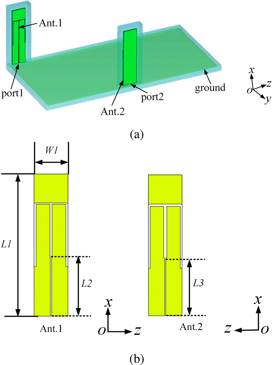
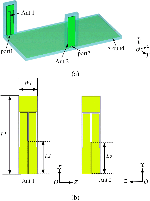
Fig. 1: Physical structure of the proposed MIMO antenna. (a) 3-D view of the whole antenna. (b) The detailed structure of the two antennas.
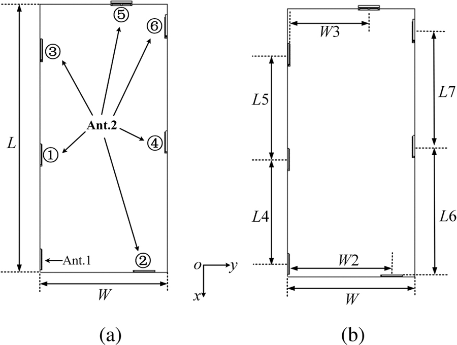
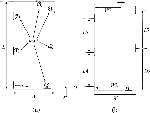
Fig. 2: Configuration of the proposed MIMO antenna system. (a) Positions of Ant. 2. (b) Dimensional parameters.
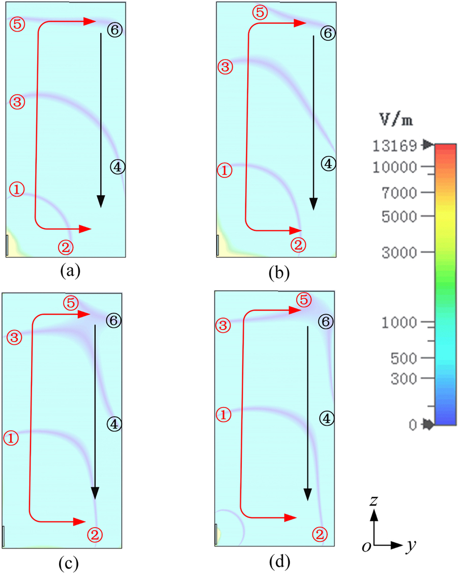
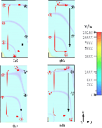
Fig. 3: Simulated E-field distribution on the ground plane at different phases. (a) 0. (b) 45. (c) 90. (d) 135\textdegree.
II. ANTENNA STRUCTURE
For easy illustration, the MIMO antenna system is simplified, as shown in Fig. 1. It is mainly composed of the ground plane and the monopole antennas, which are placed perpendicularly to the ground plane. To form a dual-antenna MIMO system with the proposed decoupling technique, after Antenna 1 (Ant. 1) is fixed on the ground plane, Antenna 2 (Ant. 2) can be freely placed on the platform. In particular, Ant. 2 is sequentially moved from points ① to ⑥ on the ground plane during the design investigation. The points’ positions are the same as those shown in Fig. 2 (a). According to the dimensions marked in Fig. 3 (b), the size of the ground plane is: L = 170 mm and W = 80 mm, and the dimensions of the monopole antenna are L1 = 50 mm and W1 = 13 mm. The physical dimension of Ant. 1 and Ant. 2 are identical. The dimensions are L4 = 66 mm, W2 = 64 mm, and L5 = 66 mm when Ant. 2 is placed at points ①-③. In the case that Ant. 2 is located at points ④-⑥, the dimensions are L6 = 74 mm, W3 = 50 mm, and L7 = 73 mm. The monopole antenna is designed using FR-4 PCB board with a thickness of 1.0 mm (4.4, tan = 0.02). In addition, the ground plane is also made up of an FR-4 substrate with 1.6 mm thickness. Table 1 tabulates the optimized dimensions of the proposed MIMO antenna system.
Table 1: Dimensions of the antenna system
| Parameter | Value | Parameter | Value |
|---|---|---|---|
| L | 170 mm | L5 | 66 mm |
| W | 80 mm | L6 | 74 mm |
| L1 | 50 mm | L7 | 73 mm |
| W1 | 13 mm | W2 | 64 mm |
| L2 | 24 mm | W3 | 50 mm |
| L3 | 23 mm | H1 | 1.0 mm |
| L4 | 66 mm | H2 | 1.6 mm |
III. WORKING MECHANISM OF THE PROPOSED DESIGN
A. Minimum point of field distribution on ground
As is well known, a monopole antenna can excite two traveling waves on the ground plane, which propagate in opposite directions along the edges [14], [15]. When these two traveling waves overlap with each other at the edges of the ground plane, an extra standing wave region can appear between the two traveling wave regions. The standing wave region contains a stable minimum point, while the traveling wave one contains a propagation minimum point.
The simulated electric field (E-field) distribution on the ground plane at 2.4 GHz at four different phases is shown in Fig. 3. It can be observed that six field amplitude minima are found on the ground plane marked by ①, ②, ③, ④, ⑤, and ⑥, respectively. Black color numbers refer to stable minimum points under the conditions of different phases, while the red ones refer to the unstable minimum points, which move along with the phases. Besides, the direction of the minimum traveling points is represented by the red arrows. While the black ones show the area covering the stable minimum points. The minimum points ① and ③ are placed at the left edge of the ground plane, and they propagate along the edge from the bottom to the top when the phase of the E-field changes. The minimum point ② is placed at the bottom edge of the ground plane and moves from left to right along the bottom edge of the ground plane. The minimum point ⑤ is placed at the upper edge of the ground plane and moves from left to right along it. On the contrary, the minimum points ④ and ⑥ are placed at the right edge of the ground plane, these points remain unchanged with the variation of the phase of the E-field.
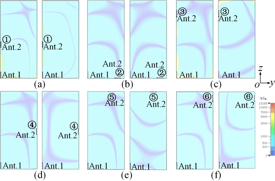
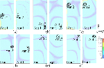
Fig. 4: Simulated E-field distribution when Ant.2 is placed at different points. (a) point ①. (b) point ②. (c) point ③. (d) point ④. (e) point ⑤. (f) point ⑥.
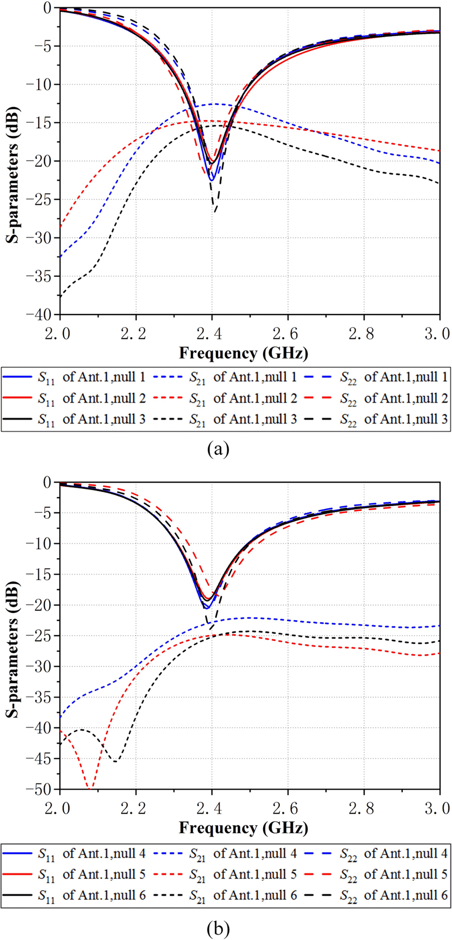
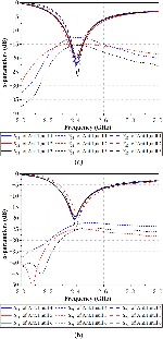
Fig. 5: Simulated S-parameters: Ant. 2 placed at the minimum points. (a) points ①-③. (b) points ④-⑥.
B. Performance of MIMO antenna system
The configuration of the proposed MIMO antenna system is provided in Fig. 2. Two monopole antennas operating at 2.4 GHz, i.e., Ant. 1 and Ant. 2, are utilized in this system. The E-field distribution on the ground plane is influenced by following factors: the antenna’s size, the antenna’s position, the shape of the ground plane, and the size of the ground plane. To obtain better isolation in the MIMO antenna system while Ant. 2 is placed at different minimum points, the size of the antenna and its ground plane should be slightly modified.
Figure 4 shows the simulated E-field when Ant. 2 is placed at the minimum points ①-⑥, which indicates that both Ant. 1 and Ant. 2 are located at the minimum points excited by the other antenna.
The simulated S-parameters in this case are shown in Fig. 5. S and S at 2.4 GHz at each minimum point are below -18 dB, but the isolation level is different. When Ant. 2 is placed at the points ①, ②, and ③, the isolation is approximately 12.5 dB, 15 dB, and 15 dB, respectively. Therefore, one can conclude that when Ant. 2 is placed at the traveling minimum point, the E-field excited by Ant. 1 is nearly zero in some particular phases around Ant. 2. Ant. 2 can still be coupled via the E-field, and energy is still transmitted between the MIMO antennas, so the isolation is not well. As can be seen in Fig. 5 (b), when Ant. 2 is placed at the stable minimum point, the isolation of the dual-monopole MIMO antenna system has a better isolation level at around 2.4 GHz. Specifically, when Ant. 2 is placed at points ④ and ⑥, the isolation is better than 22.5 dB and 25 dB respectively. In addition, when the antenna is at minimum point ⑤, the isolation is approximately 25 dB. When Ant. 2 is placed at these positions, the E-field around Ant. 2 is always close to zero. In this case, the energy transferred between the antennas is very weak, so the isolation is largely improved. Hence, a significant improvement can be obtained by optimizing the positional isolation of the MIMO antennas.
The simulated 3-D radiation patterns when Ant. 2 is placed at different minimum points are shown in Fig. 6, from which it can be observed that the radiations are not very stable when Ant. 2 is placed at the minimum points ①, ②, and ③. However, if Ant. 2 is placed at the points ④, ⑤, and ⑥, the radiation pattern is approximatively omnidirectional.
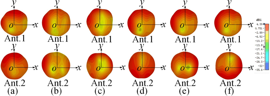
Fig. 6: The 3-D radiation patterns when Ant. 2 is placed at the minimum points ①-⑥.
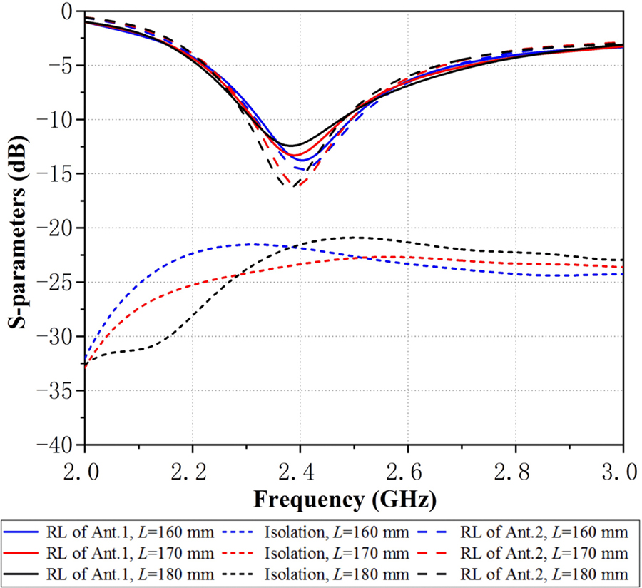
Fig. 7: Simulated S-parameters with different ground lengths (L).
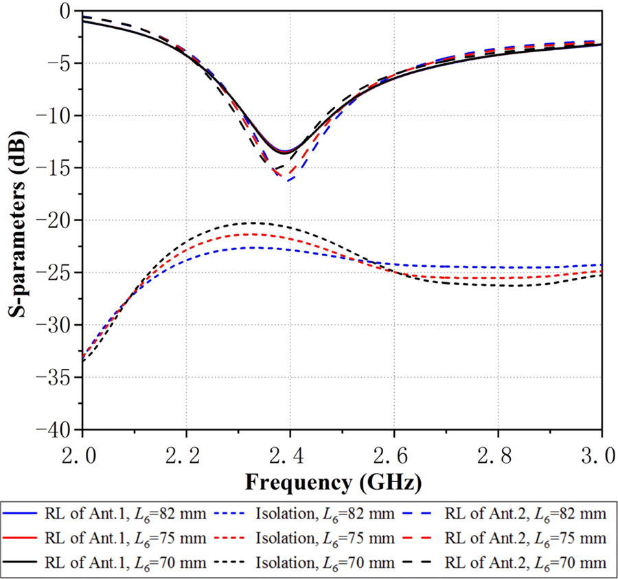
Fig. 8: Simulated S-parameters with different antenna spacings (L6).
C. Parametric study
To in order to achieve the desired MIMO antenna system, the dimensions of the antenna radiator and the ground plane can be slightly modified to reach better isolation when Ant. 2 is moved to different minimum points.
This paper performs a parametric study to find the optimum antenna position with the best isolation. Figure 7 shows the simulated reflection coefficient and isolation at different ground plane lengths (L). As the length increases, the isolation first increases and then decreases. When L = 170 mm, the entire working frequency band has the best isolation. In contrast, the reflection coefficient of the two antennas has only a slight change, which shows that the length of the ground plane will only have a certain impact on the isolation. Figure 8 shows the simulated S-parameters of the different antenna spacings (L6). With the increase of L6, the reflection coefficient of the MIMO antennas basically does not change, but the isolation becomes worse. This shows that better isolation can be obtained only when Ant. 2 is placed at a proper position.
According to the previous analysis, it can be concluded that by changing the ground plane length, antenna spacing and other parameters, the reflection coefficient of the two antennas would not change significantly, and their isolation could be affected to a certain extent. Therefore, it is necessary to select proper design parameters and ensure that there is the best isolation at 2.4 GHz to get the most compliant MIMO antenna system.
IV. RESULTS ANALYSIS
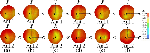
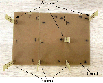
Figure 9 shows three prototypes of the proposed MIMO antennas for WLAN terminal application. The size of the prototypes is similar to a typical Wi-Fi router in the commercial market. The antennas’ location corresponds to Ant. 2 placed at the minimum point ③, point ④, and point ⑥. As shown in Fig. 9, the two monopole antennas are printed on the FR-4 dielectric substrate and fed with SMA connectors. To verify the operational characteristics, the proposed MIMO antennas are fabricated and measured.
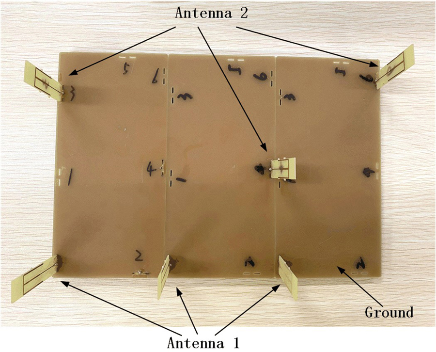
Fig. 9: Prototypes of the proposed MIMO antenna (three prototypes placed next to each other).
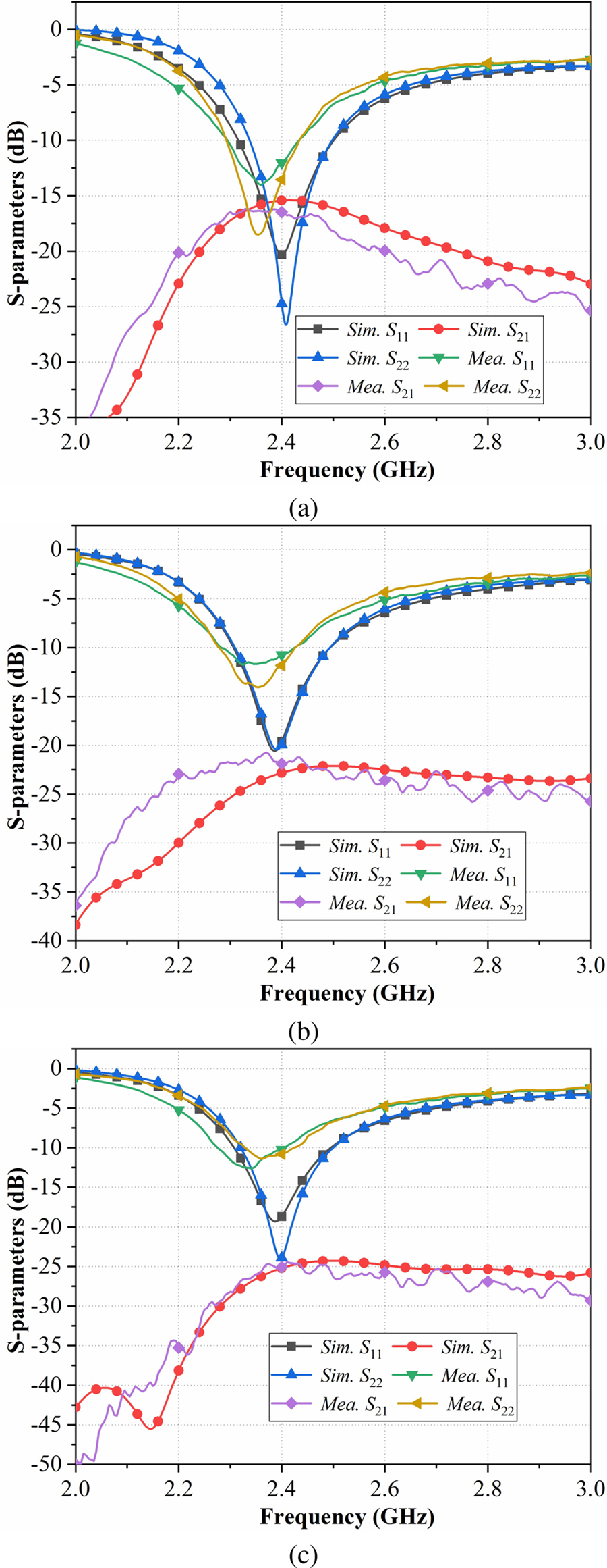
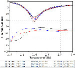
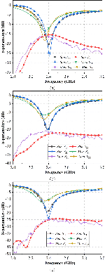
Fig. 10: S-parameters of measurement and simulation when Ant. 2 is placed at different points. (a) point ③. (b) point ④. (c) point ⑥.
As shown by the comparison chart in Fig. 10, there is a good agreement between measured and simulated results. It can be seen from Fig. 10 (a) that if Ant. 2 is placed at the point ③, S and S are both greater than -10 dB, and the port-to-port isolation is better than 15 dB at the operating frequency. Figures 10 (b) and 10 (c) show that when Ant. 2 is placed at stable minimum point ④ and point ⑥, S and S are also both below -10 dB, while the isolation can be improved to 20 dB. Compared with Fig. 10 (a), S and S are almost identical, but the isolation is improved. Generally, a larger distance between the monopole antennas will result in a better isolation. However, in the proposed MIMO antenna system, compared with Ant. 2 placed at the point ③, the spacing between the antennas is obviously shorter when Ant. 2 is at minimum point ④, but its isolation isincreasing.
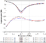
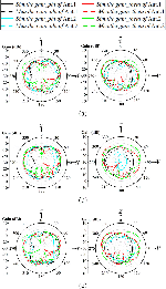
Figure 11 shows the comparison of the simulated and measured radiation pattern of proposed MIMO antennas in E-plane (xoz) and H-plane (you) at 2.4 GHz. It can be seen that the measurement result is approaching the simulation result. The results show that the peak achieved gain of Ant. 1 and Ant. 2 are both greater than 2.7 dBi.
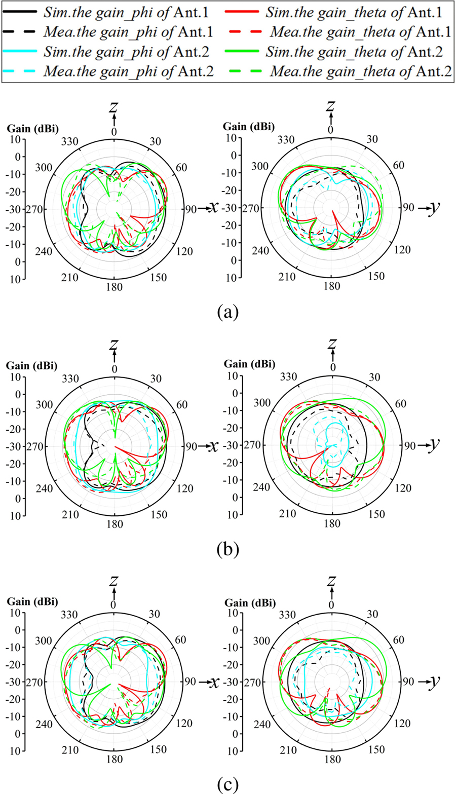
Fig. 11: The 2-D radiation patterns of measurement and simulation when Ant. 2 is placed at different points. (a) point ③. (b) point ④. (c) point ⑥.
Table 2: ECCs of the proposed MIMO antenna
| Minimum Point ③ | Minimum Point ④ | Minimum Point ⑥ | |
| ECC | 0.057 | 0.024 | 0.018 |
To verify the diversity performance of the designed MIMO antenna system, Table 2 shows the envelope correlation coefficients (ECC) when Ant. 2 is placed at minimum point ③, point ④, and point ⑥. ECC describes the level of channel independence, which is frequently used to evaluate the performance of the MIMO antenna system. The larger mode diversity of different antenna elements will produce lower ECC values, so for the MIMO antenna system, the smaller the value of ECC is, the weaker the coupling between antennas would be. It can be seen from the table that when Ant. 2 is at minimum point ③, the ECC increases; on the contrary, when it is at stable minimum point ④ and ⑥, the ECC decreases, which means the coupling between antennas is weaker. This further verifies that Ant. 2 has better radiation performance when it is at the stable minimum point.
V. CONCLUSION
This paper proposes a method for efficiently decoupling the monopole antennas from the ground plane under the operation of high-order modes, which is suitable for WLAN MIMO platform applications. The monopole antenna will generate a particular electric field distribution on the ground plane under the operation of high-order modes. These high-order modes will produce some stable E-field points. Then, by placing the other monopole antenna at these points, high isolation can be obtained between these two antennas without affecting their operation. This attractive method can realize the decoupling between antennas without utilizing extra elements or another decoupling network, which can make the decoupling mechanism simpler and also has a higher isolation value.
REFERENCES
[1] W. Shi, X. Liu, and Y. Li, “ULA fitting for MIMO radar,” IEEE Communications Letters, vol. 26, 2022.
[2] W. Shi, S. A. Vorobyov, and Y. Li, “ULA fitting for sparse array design,” IEEE Transactions on Signal Processing, vol. 69, pp. 6431-6447, 2021.
[3] F. Faraz, X. Chen, Q. Li, J. Tang, J. Li, T. A. Khan, and X. Zhang,, “Mutual coupling reduction of dual polarized low profile MIMO antenna using decoupling resonators,” Applied Computational Electromagnetics Society (ACES) Journal, vol. 35, no. 1, pp. 38-43, 2020.
[4] X. Chen, M. Zhao, H. Huang, Y. Wang, S. Zhu, C. Zhang, J. Yi, and A. A. Kishk, “Simultaneous decoupling and decorrelation scheme of MIMO arrays,” IEEE Transactions on Vehicular Technology, vol. 71, no. 2, pp. 2164-2169, Feb. 2022.
[5] B. Liu, X. Chen, J. Tang, A. Zhang, and A. Kishk, “Co- and cross-polarization decoupling structure with polarization rotation property between linearly polarized dipole antennas with application to decoupling of circularly polarized antennas,” IEEE Transactions on Antennas and Propagation, vol. 70, no. 1, pp. 702-707, Jan. 2022.
[6] B. Qian, X. Chen, and A. Kishk, “Decoupling of microstrip antennas with defected ground structure using the common/differential mode theory,” IEEE Antennas and Wireless Propagation Letters, vol. 20, no. 5, pp. 828-832, May 2021.
[7] Y. Wang, X. Chen, X. Liu, J. Yi, J. Chen, A. Zhang, and A. A. Kishk, “Improvement of diversity and capacity of MIMO system using scatterer array,” IEEE Transactions on Antennas and Propagation, vol. 70, no. 1, pp. 789-794, Jan. 2022.
[8] K. Yu, Y. Li, and X. Liu, “Mutual coupling reduction of a MIMO antenna array using 3-D novel meta-material structures,” Applied Computational Electromagnetics Society (ACES) Journal, vol. 33, no. 7, pp. 758-763, 2018.
[9] S. Luo, Y. Li, Y. Xia, and L. Zhang, “A low mutual coupling antenna array with gain enhancement using metamaterial loading and neutralization line structure,” Applied Computational Electromagnetics Society (ACES) Journal, vol. 34, no. 3, pp. 411-418, 2019.
[10] J. Jiang, Y. Xia, and Y. Li, “High isolated X-band MIMO array using novel wheel-like metamaterial decoupling structure,” Applied Computational Electromagnetics Society (ACES) Journal, vol. 34, no. 12, pp. 1829-1836, 2019.
[11] S. W. Cheung, Q. Li, D. Wu, C. Zhou, and B. Wang, “Defected ground structure with two resonances for decoupling of dual-band MIMO antenna,” IEEE International Symposium on Antennas and Propagation & USNC/URSI National Radio Science Meeting, pp. 1645-1646, 2017.
[12] Z. Li, Z. Du, M. Takahashi, K. Saito, and K. Ito, “Reducing mutual coupling of MIMO antennas with parasitic elements for mobile terminals,” IEEE Transactions on Antennas and Propagation, vol. 60, no. 2, pp. 473-481, Feb. 2012.
[13] C. Wu, C. Chiu, and T. Ma, “Very compact fully lumped decoupling network for a coupled two-element array,” IEEE Antennas and Wireless Propagation Letters, vol. 15, pp. 158-161, 2016.
[14] X. Zhao, S. P. Yeo, and L. C. Ong, “Decoupling of inverted-F antennas with high-order modes of ground plane for 5G mobile MIMO platform,” IEEE Transactions on Antennas and Propagation, vol. 66, no. 9, pp. 4485-4495, Sep. 2018.
[15] X.-Y. Ma, Z.-Y. Pang, G. Zhao, and G.-L. Huang, “An efficient decoupling technique for WLAN MIMO antenna applications,” IEEE Asia-Pacific Microwave Conference (APMC), Hong Kong, Hong Kong, pp. 75-77, 2020.
ACES JOURNAL, Vol. 37, No. 9, 970–976.
doi: 10.13052/2022.ACES.J.370906
© 2022 River Publishers