Design and Analysis of Dual Narrow Band MIMO (DNB-MIMO) Antenna for IoT Applications
Saminathan Thiruvenkadam and Eswaran Parthasarathy
1Department of Electronics and Communication Engineering, SRM Institute of Science and Technology, Chennai, Tamilnadu 603203, India
saminatt@srmist.edu.in, eswaranp@srmist.edu.in
Submitted On: July 18, 2022; Accepted On: September 20, 2022
Abstract
A compact DNB-MIMO antenna design and analysis for IoT application was proposed. The antenna radiator consists of 2 L-shaaped quarter-wavelengths and inverted 7-shaped radiators with a microstrip feed line, and partial ground plane with a size of 32 15 mm. This antenna achieves a higher quality factor (Q > 10) and narrow band impedance matching at the central frequencies of 1.8 GHz and 2.4 GHz bands with approximately 8.2% and 6.2% bandwidth respectively. The suitability of the designed antenna for IoT applications is verified through the hosting device model. The proposed 4-port MIMO antenna has an overall size of 60 60 1.6 mm, and it is printed on an FR4 substrate. The diversity add comma such as ECC, DG, TARC, MEG, and CCL, are calculated and there values are < 0.19, 9.85 dB, < -25 dB, < -6 dB, < 0.19 bits/Hz/s, respectively, within the limits. The proposed antenna is integrated with the Zigbee module (lowercase) to analyze the performance for IoT applications at 2.4 GHz.
Index Terms: DNB, DNB-MIMO, EEC, IoT, TARC, Zigbee module.
1 INTRODUCTION
The Internet of Things (IoT) is a global network of billions of physical objects that gather and send data without requiring human-to-human or human-to-computer communication. IoT implementation is found in many fields, such as smart homes, medical healthcare facilities, transportation, smart buildings, manufacturing, smart agriculture, and automation, which allows for quick decision-making based on real-time data analysis [1]. As reported in a Cisco study, between 2003 and 2020, the number of physical devices connected to the Internet increased significantly, ranging from 500 million to 50 billion [2]. Because the IoT device specifies a low data transmission rate, bandwidth needs are reduced, resulting in ultra-narrow band (UNB) modulations. Considering the above constraint, the antennas for IoT applications should be smaller and have reduced bandwidth (approximately 1MHz is also supportable for many applications), which is main challenge when designing antennas [3, 4]. It has been found that the IoT applications based on various multiband antennas [5–6], and multiband MIMO antenna designs have been investigated [7, 8, 9, 10, 11, 12, 13, 14, 15, 16, 17]. A complementary S-shape meander line has been integrated with a slotted rectangular box and capacitive load for WLAN application, showing a gain 1.347 dBi and a radiation efficiency of 79% [5]. Triangular-shaped slotted monopole antenna, E-shape monopole antenna, and two slotted patches connected to the main rectangular patch are used to achieve GSM/Bluetooth/WLAN bands [18–19]. Planar spiral loops with 4-turns for near field communication (NFC) and meander line radiator for ultra-high frequency (UHF) bands are used for IoT-based RFID reader applications [20]. Coplanar wave guide (CPW)-fed multiband patch antennas with two crossed C-shaped slots integrated into the patch and two E-shaped slots integrated into the grounded, CPW-fed slot with asymmetric T-shaped radiators are used for WLAN/WiMAX applications [21, 22, 23]. Multi-branch strips a and asymmetric CPW feed with split-ring resonator are used for LTE/WWAN/WiMAX/WLAN bands [24, 6]. In [5–6], multiband antennas where implemented for GSM/Bluetooth/LTE/WLAN/WiMAX applications. However, most of the reported multiband designs have a relatively large antenna size, less gain and lower efficiency which is not suitable for IoT applications.
Furthermore, the rapid development of a multiband MIMO antenna that utilizes multiple antennas for both the transmitter and receiver will improve channel capacity, reliable radio links, and high data rates of the wireless communication system. In [7], a circularly polarized 4-port path antenna implemented without decoupling structure is used in WLAN applications. In [8], a 4-port two identical planar inverted F-antenna implemented without decoupling network was used for WLAN/LTE/4G applications. In [9], a dual mode four elements MIMO antenna design with slits placed at the four edges of the substrate were implemented with a decoupling network for WLAN applications. In [10], a 4-port shorted patch antenna was integrated with a square-ring structure for mobile device applications. A 4-port dual-band antenna consisting of two symmetrical twisting inverted-F antenna [11]. Tunable, triangular-and C-shaped MIMO antennas with a meander line-shaped are used for LTE/ISM-2.4 GHz/5G/WiMAX bands [12–14]. For a rectangular patch antenna connected to a complementary split-ring resonator (CSRR) in the ground plane, the antenna ports are created by inserting T–shaped structure, and modified U-shaped resonator were used to reduce mutual coupling between the ports [15, 16, 17]. The literature review on multiband MIMO antennas show that the most essential frequency bands, such as LTE/GSM/WLAN/4G/WiMAXA applications, are covered. However, the most widely reported multiband MIMO designs have a relatively large antenna size, and mutual coupling between the ports are used several techniques, such as parasitic elements, metamaterials, electromagnetic band gap structure (EBG) [8, 9, 15, 16, 17].
In this article, a simple, compact, and DNB-MIMO antenna for IoT applications is presented. The designed antenna front side two radiators and backside two radiators are placed in the FR4 substrate without decoupling structure. The antenna element has a Quarter wavelength of L-shaped, and inverted 7-shaped stubs are loaded with microstrip line to achieves the dual narrow band (DNB). The designed antenna has a size of 60 60 1.6 mm.
2 DESIGN CONFIGURATION AND ANALYSIS OF DNB ANTENNA
In this section, we have discussed the unit element design, equivalent circuit model, surface current distribution at operating bands, hosting effect, and MIMO antenna design.
2.1 Design of unit element
The dimension of the proposed DNB antenna is depicted in Fig. 1. The front of the substrate is composed of an L-shaped and inverted 7-shaped radiators integrated with 50- feed line. The back side of the substrate optimized partial ground plane. The unit element is designed on a FR4 substrate with a thickness of 1.6 mm, , and a conductor (copper) thickness = 0.035 mm. The overall size of the proposed unit element is 32 15 mm, and the optimized dimensions are listed in Table 1. Figures 2 (a)-(b) describes the development stages of the DNB antenna. The DNB antenna is accomplished due to L-shaped and inverted 7-shaped radiators, and it can be determined by following Equation (1). The f and fare operating frequency due to L-shaped and inverted 7-shaped radiator respectively.
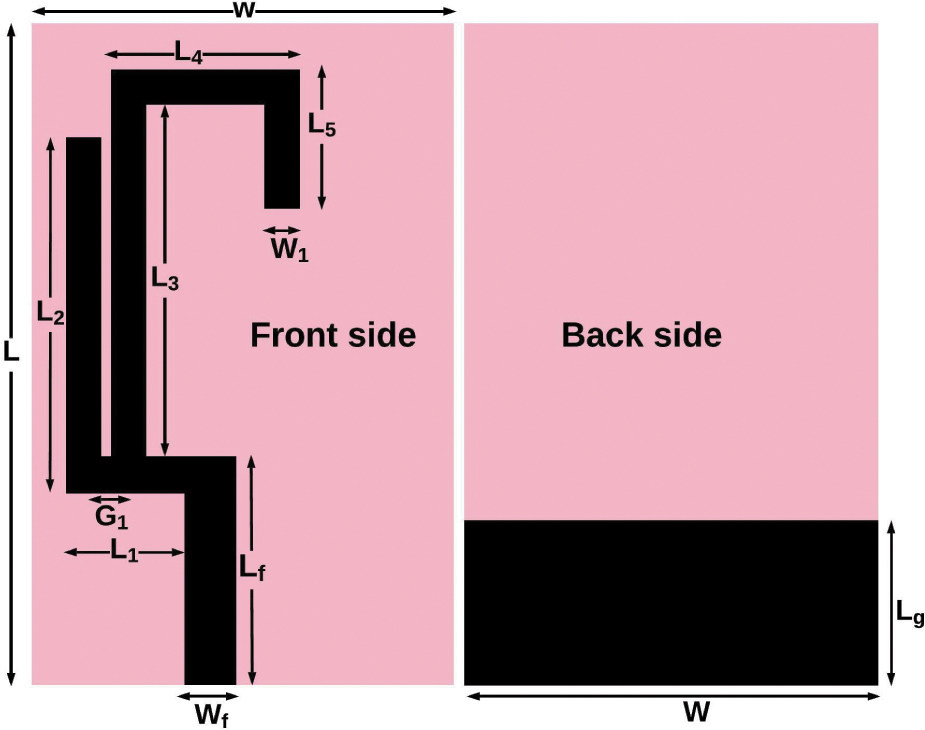
Figure 1: Proposed DNB unit element.
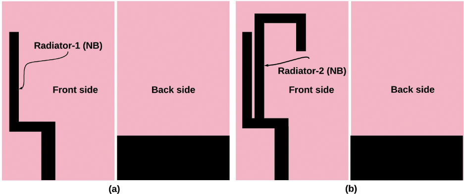
Figure 2: Development stages of DNB antenna (a) Antenna-1, (b) Antenna-2.
| (1) |
where
where ’C’ is speed of light, is effective dielectric constant, is dielectric constant of substrate, and is total length of stub radiator which is responsible for operating mode.
Table 1: Dimension of proposed unit element
| Parameters | values (mm) | Parameters | values (mm) |
| L | 32 | L | 9.5 |
| L | 11 | L | 6 |
| L | 5.5 | W | 15 |
| L | 19 | W | 3 |
| L | 20 | W | 1.5 |
| L | 8 | G | 0.5 |
2.1.1 Antenna-1
A quarter wavelength of L-shaped radiator-1 and an optimized partial ground plane of L W is designed with a 3 mm wide microstrip feed line as shown in the Fig. 2 (a).
| (2) |
where L, L are length of L, Wis the width of Land is guided wavelength. The length of the L-shaped stub (L) is calculated using length and width of the L as mentioned in Equation (2) and it is 30 mm approximately. The antenna-1 operating frequency f is theoretically calculated at 2.4 GHz and while the simulated operating frequency is 2.5 GHz as illustrated in Fig. 3, which is very close to theoretical value.
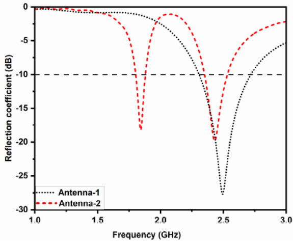
Figure 3: Reflection coefficient (S) of designed unit element.
2.1.2 Antenna-2:
A quarter wavelength of the inverted 7-shaped radiator-2 connected with antenna-1. Antenna-2 consists of L-shaped, inverted 7-shaped radiator connected with a feed line and an optimized partial ground plane, as shown in Fig. 2 (b).
| (3) |
where L is the length of the inverted 7-shaped radiator-2. L, L and L5 are the length of L, and W is the width of L. The length of the inverted 7-shaped stub (L) is calculated using the length and width of the L as mentioned in Equation (3) and it is 40 mm approximately. The radiator-2 operating frequency f is theoretically calculated at 1.8 GHz and while the simulated operating frequency is 1.85 GHz as depicted in Fig. 3, which is very close to the theoretical value. It was found that antenna-2 operates dual-mode at 1.85 GHz and 2.45 GHz due to the inverted 7-shaped and L-shaped radiators. The reflection coefficient of the proposed antenna-2 is < -10 dB at the operating bands. Further, the proposed unit element covers the GSM (1.75-1.9 GHz) and WLAN (2.34-2.55 GHz) bands.
2.2 Equivalent circuit of designed element
The antenna’s physical mechanism is investigated using the equivalent circuit. The equivalent circuit is calculated by using proposed the antenna impedance characteristic as shown in Fig. 4. It can be seen that the impedance curve at resonance frequency real part is around 50 and imaginary part nearly equivalent to 0 . Further, the impedance curve at resonance frequency goes from high (positive) to low (negative), so a parallel RLC resonant circuit is drawn [25, 26] . The dual-band antenna consist of 7-shaped and L-shaped stub, hence the two parallel RLC circuits used to generate a dual-band through lumped equivalent circuit model are depicted in Fig. 5. The S-Parameters of the lumped equivalent circuit model is illustrated in Fig. 6. It can be observed that S-Parameters of EM model and equivalent circuit model provide identical performance.
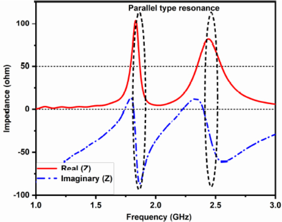
Figure 4: Impedance characteristic of designed antenna.
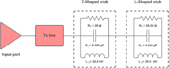
Figure 5: Equivalent circuit model of designed antenna.
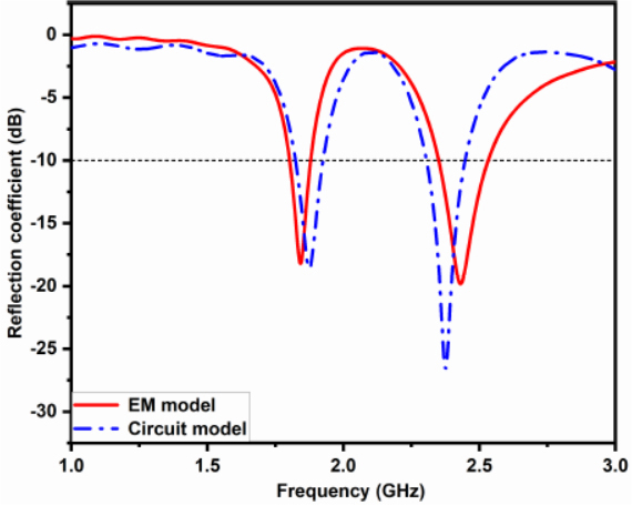
Figure 6: Comparison of the reflection coefficient of the circuit model and the EM model.
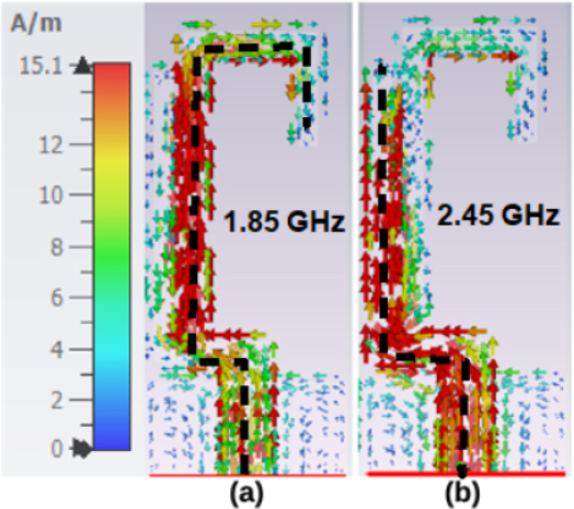
Figure 7: Surface current distribution of the proposed unit element.
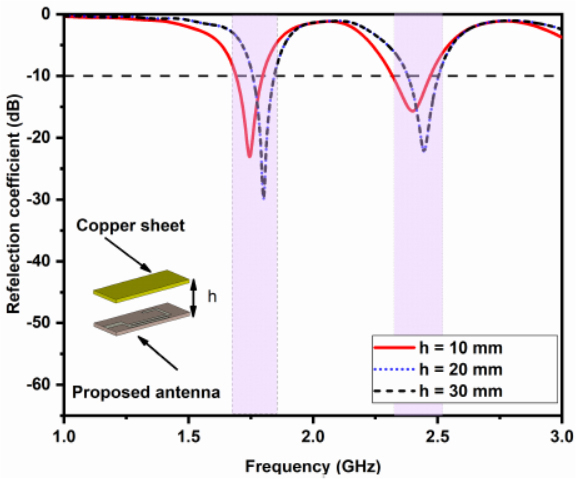
Figure 8: Reflection coefficient of the dual band antenna with a copper plate at the distance ‘h’.
2.3 Surface current distribution of DNB antenna
The surface current distribution of the proposed unit element has been investigated and illustrated in the Fig. 7. Figure 7 (a) represent the current distribution at 1.85 GHz, and the maximum current density available in radiator-2. A current density value of approximately 0.3926 A/mm is observed in radiator-2. Figure 7 (b) represent the current distribution at 2.45 GHz, and the maximum current density available in radiator-1. A current density value of approximately 0.5436 A/mm is observed in radiator-1. Hence, the surface current distribution shows that the fundamental resonance of two radiators is seen to be independent of the change in radiator length and mutual coupling between two radiators is adjusted.
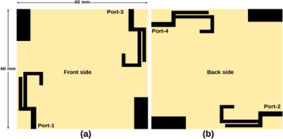
Figure 9: Schematic diagram of designed MIMO antenna.
2.4 Hosting effect
The performance of the designed antenna is verified considering it as a host device in IoT applications. The antenna is mounted below a copper sheet size of 32 15 mm at a distance h of 10 to 30 mm to investigate the hosting effect [27, 28, 29]. The proposed antenna reflection coefficients are investigated after being mounted in the host device, as shown in Fig. 8. It is found that the antenna can operate in dual-band whenever substrate-sized ground plane is mounted in the far near-field region. Thus, the copper sheet has less impact on the antenna performance, indicating that it will work reliably in IoT devices.
2.5 Design of 4-port MIMO antenna
The designed unit element is used in a MIMO system that utilizes multiple ports as transmitters and receivers to enhance the channel capacity for IoT applications. The designed has a size of 60 60 1.6 mm, as shown in the Fig. 9. The designed antenna was printed identically on double-sided FR4 substrate and each side contains two elements with an optimized partial ground plane that are connected to two other elements printed on the other side. MIMO elements are placed in an orthogonal arrangement on both sides to reduce mutual coupling between ports. The simulated reflection coefficients of the MIMO antenna are depicted in Fig. 10. It is perceived that the designed antenna achieves narrow bandwidth at center frequency of 1.8 GHz and 2.4 GHz with reflection coefficient of< -10 dB.
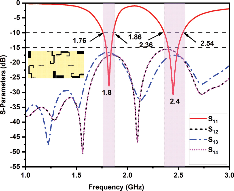
Figure 10: S-parameters of designed antenna at Port 1 (Simulated).
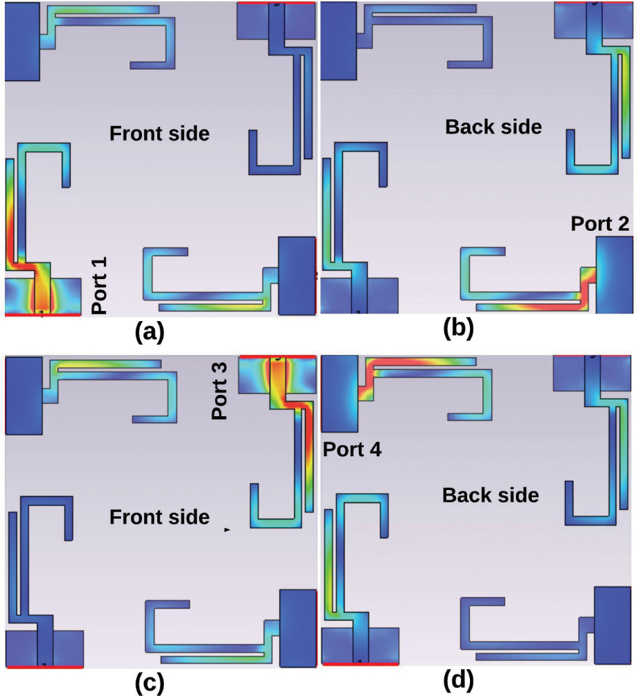
Figure 11: Surface current distribution of designed 4-port MIMO antenna at 2.4 GHz with excitation applied at (a) Port 1, (b) Port 2, (c) Port 3, and (d) Port 4.
The designed MIMO antenna uses double-sided placement techniques such as radiators and ground planes on both sides because it has less mutual coupling between the ports (S, S, S) as shown in the Fig. 10. It has been observed that the mutual coupling between the two ports is < -15 dB over the entire operating band. In addition, the surface current distribution results of the proposed antenna used to validate the mutual coupling between the ports is depicted in Fig. 11. In this 4-port MIMO antenna design, when every port is excited and remain ports are connected to 50- matched the loaded, a negligible amount of current flows to other ports. Hence, the need for a decoupling structure was eliminated.
3 RESULTS AND DISCUSSIONS OF PROPOSED 4-PORT MIMO ANTENNA
The designed MIMO antenna fabricated on FR4 substrate is depicted in Fig. 12. The simulation results are experimentally verified for the antenna reflection coefficients, farfield radiation pattern, gain, and efficiency measured using the N9926A vector network analyzer and anechoic chamber.
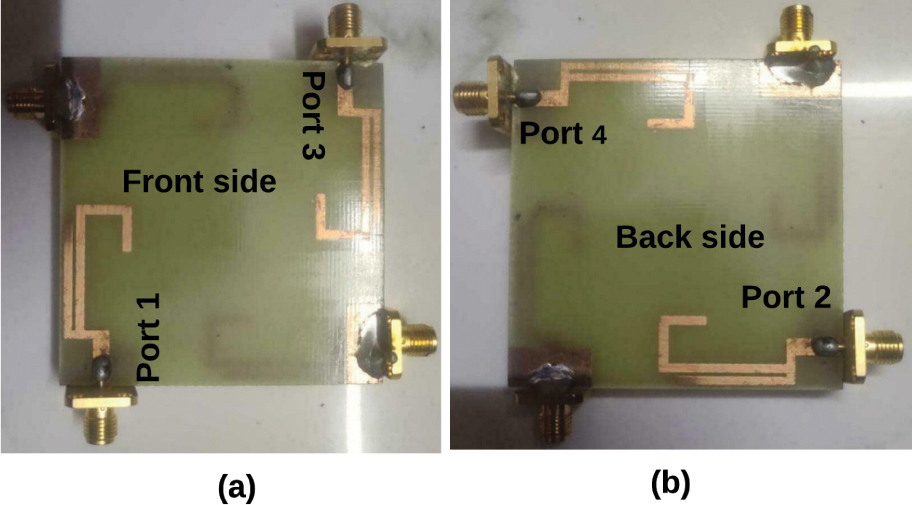
Figure 12: Prototype of designed antenna.
3.1 Reflection coefficients
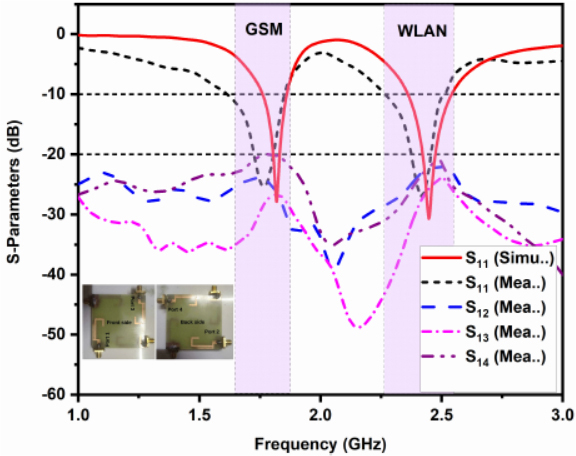
Figure 13: S-parameters of designed antenna at Port 1 (Simulated and Measured).
The proposed antenna simulated and measured reflection coefficients are illustrated in Fig. 13. The antenna is resonating dual-band center frequencies of 1.8 and 2.4 GHz and covers two different narrow bandwidth of 130 MHz (1.7–1.83 GHz) and 190 MHz (2.33–2.52 GHz) at < -10 dB, which covers GSM and WLAN bands. The mutual coupling between port 1 to port 2, port 1 to port 3, and port 1 to port 4 are < -20 dB at the operating bands, which shows the simulated and measured results are in good agreement.
3.2 Radiation pattern
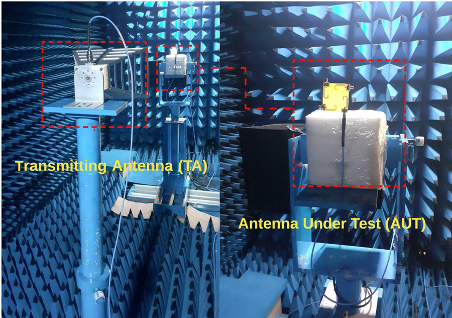
Figure 14: Radiation pattern measurements of designed antenna in anechoic chamber.
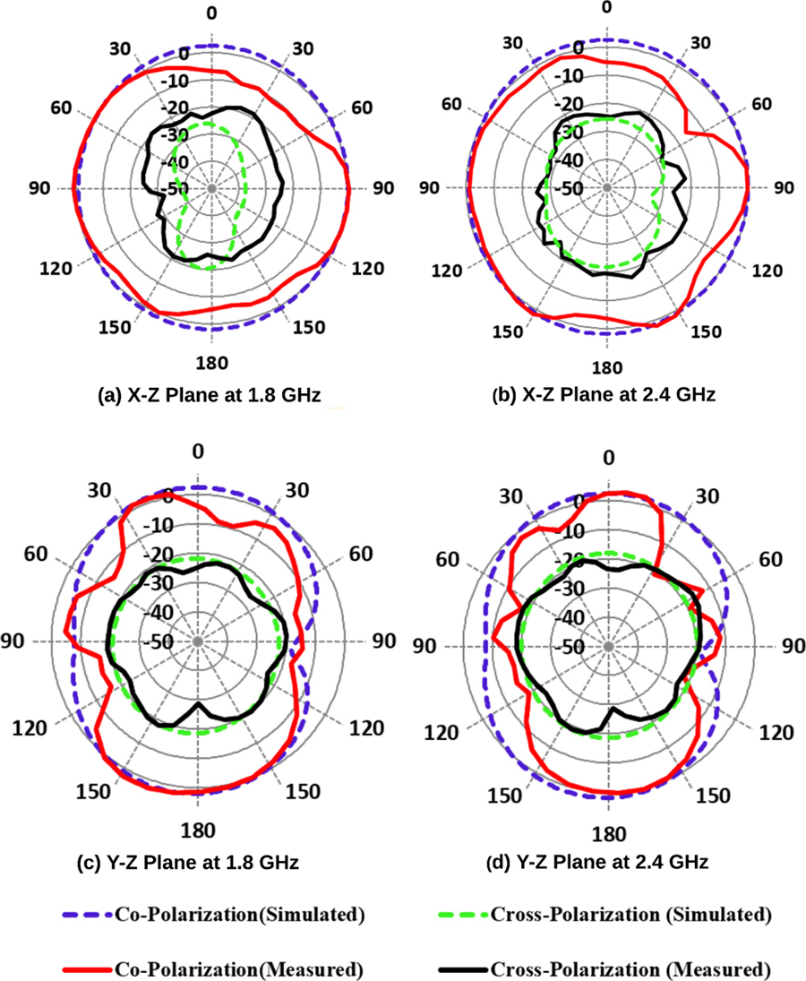
Figure 15: Radiation patterns of designed antenna (a) X-Z plane at 1.8 GHz, (b) X-Z Plane at 2.4 GHz, (c) Y-Z plane at 1.8 GHz, (d) Y-Z Plane at 2.4 GHz.
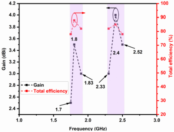
Figure 16: Gain and total efficiency of the designed 4-port MIMO antenna is measured at Port 1.
The antenna radiation pattern, gain, and efficiency are measured using an anechoic chamber at port 1 and the measurement environment is shown in Fig. 14. The coplanar and cross polarization of electric and magnetic field distribution of the designed antenna excited in port 1 is depicted in Figs. 15 (a)-(b) for 1.8 GHz and 2.4 GHz respectively.The designed antenna exhibits an omnidirectional radiation pattern in a simulation study as well as in experimental measurement. It shows good agreement among the measured values.
3.3 Gain and efficiency
The measured gain and total efficiency of the proposed 4-port MIMO antenna at port 1 from the far-field distance is depicted in Fig. 16. It is perceived that the peak gain of 3.2 dBi and 4 dBi is attained in 1.8 GHz and 2.4 GHz respectively. The total efficiency measured at 1.8 GHz is 85% and at 2.4 GHz is 93.57%. Hence, the designed antenna achieves an overall peak gain > 3 dbi and total efficiency > 78% in the operating bands and is illustrated in Fig. 16.
3.4 MIMO parametric analysis of proposed antenna
The essential diversity metrics of the proposed MIMO antenna are discussed in this section using calculated and measured values of reflection coefficient, mutual coupling and radiation pattern.
3.4.1 ECC
Envelope correlation coefficient (ECC) is an essential metric for the MIMO antenna. It determines the correlation between the antenna radiating elements. The ECC can be computed using far-field patterns as given in Equation (4), where S and S are the electric fields radiated, and , , and d are the elevation, azimuthal, and beam area, respectively. The real-time best value of ECC should be < 0.5 in all operating bands [30, 31].
| (4) |
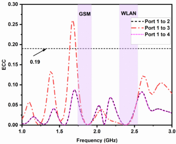
Figure 17: ECC of designed antenna (Measured).
3.4.2 DG
The diversity gain (DG) is calculated by using farfield ECC value as given in Equation (5) [32]:
| (5) |
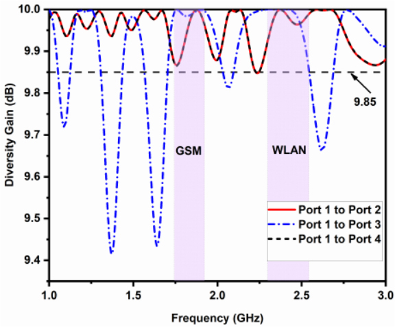
Figure 18: DG of designed antenna (Measured).
3.4.3 TARC
The total active reflection coefficient (TARC) is a mathematical expression that relates to the total incident power with the total radiated power of a MIMO antenna. TARC is calculated between two-port MIMO antennas by using Equation (6). The most suitable value of TARC is expected to be < 0 to have good diverse performance for MIMO system [33].
| (6) |
Where, is lies from 0 to 360
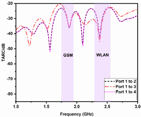
Figure 19: TARC of designed antenna (Measured).
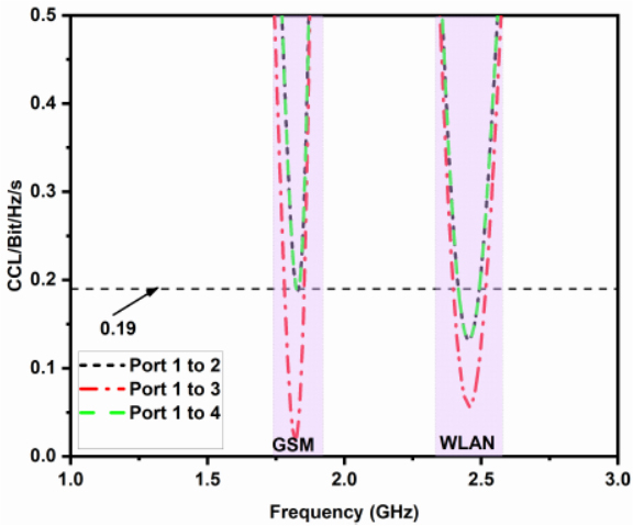
Figure 20: CLL of designed antenna (Measured).
3.4.4 CCL
The channel capacity loss (CCL) is a significant metric in MIMO performance since it grows linearly with the number of antenna elements employed under a given assumption, without affecting the transmitted power or bandwidth. MIMO channel systems suffer from capacity loss as a result of the elements’ correlation. The CCL parameter is determined by the Equation (7).
| (7) |
where is correlation of the receiving antenna. The allowable limit for CCL is typically < 0.4 bps/Hz [34]. The designed MIMO antenna measured CCL is plotted in Fig. 20 and the value of CCL is < 0.19 bits/Hz/s at the resonating bands.
Table 2: Measured MEG of designed antenna
| Frequency (GHz) | MEG-1 | MEG-2 | MEG-3 | MEG-4 | MEG-1/MEG-2 | MEG-3/MEG-4 |
|---|---|---|---|---|---|---|
| 1.8 | -8.44 | -8.53 | -8.42 | -8.51 | 0.989 | 0.989 |
| 2.4 | -6.76 | -6.93 | -6.86 | -6.84 | 1.002 | 1.002 |
Table 3: Comparison between proposed work and existing work
| Ref.No | Size (mm) | M | N | BW (GHz) | MC (dB) | ECC | TARC | App |
|---|---|---|---|---|---|---|---|---|
| [15] | 96 96 | FR4 | 2 | 2.4-2.485 | <-25 | <0.4 | - | WLAN |
| [16] | 50 100 | FR4 | 2 | 2.0-3.6 | <-17 | <0.3 | - | IoT |
| [17] | 46 20 | FR4 | 4 | 2.4-2.5, 4.9-5.7 | <-12 | <0.3 | - | WLAN |
| [18] | 66 66 | FR4 | 4 | 2.4-2.484, 5.7-5.8 | <-12 | <0.1 | - | WLAN |
| [19] | 52 77 | FR4 | 2 | 2.4-2.48, 5.15 -5.82 | <-15 | <0.3 | - | WLAN |
| [20] | 80 54 | FR4 | 2 | 1.06-1.24, 1.52-2.13, 2.19-2.63 | <-14 | <0.5 | - | Radio/LTE/ISM |
| [21] | 60 20 | FR4 | 2 | 2.4-2.48, 3.4-3.6, 5.3-5.9 | <-20 | <0.08 | - | WLAN/WiMAX |
| [22] | 150 75 | FR4 | 4 | 3.4-3.6 | <-17.5 | <0.09 | <-8.6 | 5G |
| [23] | 106 95 | FR4 | 4 | 2.29-2.49,2.85-3.04, 5.61-5.80 | <-17 | <0.01 | <-20 | WLAN |
| PS | 60 60 | FR4 | 4 | 1.7-1.83,2.33-2.52 | <-21 | <0.19 | <-21 | IoT |
M-Material, N-refers to number of radiators, BW-Bandwidth, MC-Mutual Coupling, App-Application
3.4.5 MEG
In multi-path fading situations, the mean effective gain (MEG) is defined as the ratio of the received mean power of the diversity antenna to the received mean power of the isotropic antenna and as given in Equation (8) is used to determine S-parameters of individual ports.
| (8) |
where N is number ports and i is the active port.
The computed MEG-1, MEG-2, MEG-3, MEG-4 values are given in Table 2, which is lies standard range of -3 MEG(dB) < -12 [35, 36]. Further, the ratio of MEG1/MEG2 and MEG3/MEG4 are closed to one, which complies with the multi-path fading standard.
3.4.6 Performance comparison
The designed antenna parameters are compared with previously reported works of MIMO antenna and it is given in Table 3.
• The designed antenna structure is compact when compared to previously reported works [7, 8, 10, 11, 12, 14, 15].
• The mutual coupling of the designed antenna are better than those of [8–15] without a decoupling structure.
• This work also concentrated on the ECC and TARC of the MIMO design. The proposed antenna has a lower ECC than [7, 8, 9, 11, 12] because of the low mutual coupling characteristics. TARC was not reported in [7–13], and a lower TARC value is exhibited when compared with [14, 15].
• The proposed MIMO antenna has been validated for real-time IoT applications.
3.4.7 Implementation of designed MIMO antenna for smart home application
Real-time implementation is carried out for IoT-based home automation applications in which the sensor modules are embedded with designed antenna operating at 2.4 GHz. The experimental setup depicted in Fig. 21 (a) consists of IoT 2040 gateway, three Zigbee modules (CC2538 kit) embedded with a designed 4-port MIMO antenna integrated with temperature, light, humidity sensors respectively.
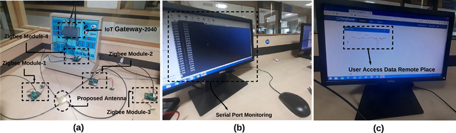
Figure 21: Experimental setup of IoT based smart home application by using proposed antenna.
In this 4-port MIMO antenna, Port 1, Port 2, and Port 3 are connected sensor modules and Port 4 is connected to the coordinating sensor module.The Winx serial port monitor is used to display the status of the sensor data acting as a host computing device and it is shown in Fig. 21 (b). This sensor data can be used remotely using a cloud platform (ThinkSpeak) and is shown in Fig. 21 (c). The smart home application is implemented in a closed room environment. Each sensor module trasmits sensor data at a rate of 64 kbps through IoT 2040 gateway to the host computing device, which is connected to the IoT cloud . This data can be accessed from any device remotely.
4 CONCLUSION
A multi-stub-based 4-port dual narrow band MIMO antenna is designed and fabricated and the characteristics are analyzed experimentally for IoT applications. The designed antenna exhibits dual narrow bandwidth of 1.8 GHz (1.7–1.83 GHz) and 2.4 GHz (2.33-2.52 GHz) which covers the GSM/WLAN frequency band. In the operating bands, the antenna’s important metrics, such as reflection coefficient of < -10 dB, mutual coupling of < -21 dB between the ports, peak gain of > 3 dbi, nearly omnidirectional radiation pattern, and total efficiency of > 78%, are obtained experimentally. The hosting effect of proposed antenna is examined. The diversity metrics, such as ECC, DG, TARC, CCL, and MEG, are experimentally analyzed and found to be within the limits. The designed MIMO antenna performance compared with previous work shows better results. We have also demonstrated the implementation of the designed antenna in a real-time application. This proposed antenna can also be used to integrate sensor modules in a larger IoT network.
REFERENCES
[1] A. Al-Fuqaha, M. Guizani, M. Mohammadi, M. Aledhari, and M. Ayyash, “Internet of things: A survey on enabling technologies, protocols, and applications,” IEEE Communications Surveys & Tutorials, vol. 17, no. 4, pp. 2347-2376,2015.
[2] D. Evans, “The internet of things: How the next evolution of the internet is changing everything,” CISCO white paper, vol. 1, no. 2011, pp. 1-11, 2011.
[3] S. Zhang, “Spectrum aanlyses of UNB modulation formats,” in 2013 3rd International Conference on Consumer Electronics, Communications and Networks, pp. 594-597, 2013.
[4] A. De, B. Roy, and A. K. Bhattacharjee, “Miniaturized dual band consumer transceiver antenna for 5G-enabled IoT-based home applications,” International Journal of Communication Systems, p. e4840, Jul. 2021.
[5] M. S. Islam, M. T. Islam, M. A. Ullah, G. K. Beng, N. Amin, and N. Misran, “A modified meander line microstrip patch antenna with enhanced bandwidth for 2.4 GHz ISM-band Internet of Things (IoT) applications,” IEEE Access, vol. 7, pp. 127850-127861, Sep. 2019.
[6] K. K. Naik, “Asymmetric CPW-fed SRR patch antenna for WLAN/WiMAX applications,” AEU-International Journal of Electronics and Communications, vol. 93, pp. 103-108,Sep. 2018.
[7] E. Zhang, A. Michel, M. R. Pino, P. Nepa, and J. Qiu, “A dual circularly polarized patch antenna with high isolation for MIMO WLAN applications,” IEEE Access, vol. 8, pp. 117833-117840, Jun. 2020.
[8] H. T. Chattha, “Compact high isolation wideband 4G and 5G multi-input multi-output antenna system for handheld and internet of things applications,” International Journal of RF and Microwave Computer-Aided Engineering, vol. 29, no. 6, p. e21710, Jun. 2019.
[9] S. Soltani, P. Lotfi, and R. D. Murch, “A dual-band multiport MIMO slot antenna for WLAN applications,” IEEE Antennas and Wireless Propagation Letters, vol. 16, pp. 529-532, Jul. 2016.
[10] K.-L. Wong, C.-J. Chen, and W.-Y. Li, “Integrated four low-profile shorted patch dual-band WLAN MIMO antennas for mobile device applications,” IEEE Transactions on Antennas and Propagation, vol. 69, no. 6, pp. 3566-3571,Nov. 2020.
[11] J. Deng, J. Li, L. Zhao, and L. Guo, “A dual-band inverted-F MIMO antenna with enhanced isolation for WLAN applications,” IEEE Antennas and Wireless Propagation Letters, vol. 16, pp. 2270-2273, Jun. 2017.
[12] B. BharathiDevi and J. Kumar, “Small frequency range discrete bandwidth tunable multiband MIMO antenna for radio/LTE/ISM-2.4 GHz band applications,” AEU-International Journal of Electronics and Communications, vol. 144, p. 154060, Feb. 2022.
[13] S. Pandit, A. Mohan, and P. Ray, “Compact frequency-reconfigurable MIMO antenna for microwave sensing applications in WLAN and WiMAX frequency bands,” IEEE sensors letters, vol. 2, no. 2, pp. 1-4, Apr. 2018.
[14] A. T. Z. Moses, N. Moses, and D. K. Janapala, “An electrically small 4-port self-decoupled MIMO antenna pairs operating in n78 5G NR band for smartphone applications,” AEU-International Journal of Electronics and Communications, p. 154082, Feb. 2021.
[15] M. Aminu-Baba, M. K. A. Rahim, F. Zubir, A. Y. Iliyasu, K. I. Jahun, M. F. M. Yusoff, M. M. Gajibo, A. A. Pramudita, and I. K. C. Lin, “A compact triband miniaturized MIMO antenna for WLAN applications,” AEU-International Journal of Electronics and Communications, vol. 136, p. 153767, Jul. 2021.
[16] H. Yon, M. A. Aris, N. H. A. Rahman, N. M. Nasir, and H. Jumaat, “A Design of Decoupling Structure MIMO Antenna for Mutual Coupling Reduction in 5G Application,” in 2019 International Symposium on Antennas and Propagation (ISAP), pp. 1-3, 2019.
[17] A. Iqbal, A. Altaf, M. Abdullah, M. Alibakhshikenari, E. Limiti, and S. Kim, “Modified U-shaped resonator as decoupling structure in MIMO antenna,” Electronics, vol. 9, no. 8, p. 1321, Aug. 2020.
[18] M. Dehmas, A. Azrar, F. Mouhouche, K. Djafri, and M. Challal, “Compact dual band slotted triangular monopole antenna for RFID applications,” Microwave and Optical Technology Letters, vol. 60, no. 2, pp. 432-436, Feb. 2018.
[19] S. Katoch, H. Jotwani, S. Pani, and A. Rajawat, “A compact dual band antenna for IOT applications,” in 2015 International Conference on Green Computing and Internet of Things (ICGCIoT), pp. 1594-1597, 2015.
[20] A. Romputtal and C. Phongcharoenpanich, “IoT-linked integrated NFC and dual band UHF/2.45 GHz RFID reader antenna scheme,” IEEE Access, vol. 7, pp. 177832-177843, Dec. 2019.
[21] A. M. Saadh and R. Poonkuzhali, “A compact CPW fed multiband antenna for WLAN/INSAT/WPAN applications,” AEU-International Journal of Electronics and Communications, vol. 109, pp. 128-135, Sep. 2019.
[22] Chandan, “Truncated ground plane multiband monopole antenna for WLAN and WiMAX applications,” IETE Journal of Research, pp. 1-6, Jan. 2020.
[23] K.-L. Wong, H.-J. Chang, C.-Y. Wang, and S.-Y. Wang, “Very-low-profile grounded coplanar waveguide-fed dual-band WLAN slot antenna for on-body antenna application,” IEEE Antennas and Wireless Propagation Letters, vol. 19, no. 1, pp. 213-217, Dec. 2019.
[24] Ming-An Chung, “A miniaturized triple band monopole antenna with a coupled branch strip for bandwidth enhancement for IoT applications,” Microwave and Optical Technology Letters, vol. 60, no. 9, pp. 2336-2342, Sep. 2018.
[25] S. Luo, D. Wang, Y. Chen, E. Li, and C. Jiang, “A compact dual-port UWB-MIMO antenna with quadruple band-notched characteristics,” AEU-International Journal of Electronics and Communications, vol. 136, p. 153770, Jul. 2021.
[26] L. S. Yahya, L. S. Yahya, and K. H. Sayidmarie, “Dual-band folded monopole MIMO antennas with enhanced isolation,” Applied Computational Electromagnetics Society (ACES) Journal, pp. 1569-1578, Dec. 2021.
[27] U. Bashir, K. R. Jha, G. Mishra, G. Singh, and S. K. Sharma, “Octahedron-shaped linearly polarized antenna for multistandard services including RFID and IoT,” IEEE Transactions on Antennas and Propagation, vol. 65, no. 7, pp. 3364-3373, May 2017.
[28] N. K. Maurya and R. Bhattacharya, “Design of compact dual-polarized multiband MIMO antenna using near-field for IoT,” AEU-International Journal of Electronics and Communications, vol. 117, p. 153091, Apr. 2020.
[29] S. Thiruvenkadam, E. Parthasarathy, S. K. Palaniswamy, S. Kumar, and L. Wang, “Design and performance analysis of a compact planar MIMO antenna for IoT applications,” Sensors, vol. 21, no. 23, p. 7909, Nov. 2021.
[30] M. S. Sharawi, “Printed multi-band MIMO antenna systems and their performance metrics [wireless corner],” IEEE Antennas and Propagation Magazine, vol. 55, no. 5, pp. 218-232, 2013.
[31] P. Prabhu and S. Malarvizhi, “Compact dual-band hybrid-fractal MIMO system for UMTS and LTE mobile applications,” Applied Computational Electromagnetics Society (ACES) Journal, pp. 135-140, Jan. 2019.
[32] Z.-J. Tang, J. Zhan, B. Zhong, L. Cheng, and G. Zuo, “Design of a coplanar UWB-MIMO ground antenna based on the theory of characteristic modes,” Progress in Electromagnetics Research C, vol. 117, pp. 221-237, 2021.
[33] J. Kulkarni, A. Desai, and Chow-Yen-Desmond Sim, ‘‘Two port CPW-fed MIMO antenna with wide bandwidth and high isolation for future wireless applications,” International Journal of RF and Microwave Computer-Aided Engineering, p. e22700, Aug. 2021.
[34] K. Srivastava, S. Kumar, B. K. Kanaujia, S. Dwari, H. C. Choi, and K. W. Kim, “Compact eight-port MIMO/diversity antenna with band rejection characteristics,” International Journal of RF and Microwave Computer-Aided Engineering, vol. 30, no. 5, p. e22170, May 2020.
[35] A. A. Khan, M. H. Jamaluddin, J. Nasir, R. Khan, S. Aqeel, and J. Saleem, “Design of a dual-Band MIMO dielectric resonator antenna with pattern diversity for WiMAX and WLAN applications,” Progress in Electromagnetics Research M, vol. 50, pp. 65-73, 2016.
[36] D. H. Sadek, H. A. Shawkey, and A. A. Zekry, “Multiband triple L-arms patch antenna with diamond slot ground for 5G applications,” Applied Computational Electromagnetics Society (ACES) Journal, pp. 302-307, Mar. 2021.
BIOGRAPHIES

T. Saminathan received his B.E. degree in Electronics and Communication Engineering from King College of Engg, Tamil Nadu, India (affiliated to Anna University, Chennai) in 2008 and M.Tech degree in Embedded System and Technology from SRM University, Tamil Nadu, India, in 2012. Presently, he is working as an assistant professor in SRMIST and pursuing a Ph.D. degree in the Department of Electronics and Communication Engineering at SRMIST, Chennai, India. His research interests include monopole antenna design, multi-band antennas, and MIMO antenna design.

P. Eswaran received his Bachelor degree in Electronics and Telecommunication Engineering from the Institute of Engineers (India) in 2000, Master’s in Mechatronics in 2003 from Madras Institute of Technology (India), and Ph.D. in Electronics and Communication Engineering from SRM University in 2014. He currently works as Professor in Department of Electronics and Communication Engineering at SRMIST (Formerly known as SRM University). His areas of interest are MEMS, VLSI, Device Modeling, EV and PV systems, embedded systems and Industry 4.0. He has published over 30 reviewed international journal/conference papers, and two Indian patents. He has served as a reviewer for peer reviewed journals. He is also Fellow Member of IE (India), Life Member of IETE, and ISTE professional bodies.
ACES JOURNAL, Vol. 37, No. 8, 901–911.
doi: 10.13052/2022.ACES.J.370809
© 2022 River Publishers