Uncertainty Quantification Method of Crosstalk Involving Braided-Shielded Cable
Tianhong Tan, Tao Jiang, Haolin Jiang, Tianhao Wang, and Mingjuan Cai
1College of Information and Communication Engineering
Harbin Engineering University, Harbin, 150001, China
tthjob@163.com, jiangtao@hrbeu.edu.cn
2College of Instrumentation & Electrical Engineering
Jilin University, Changchun, 130000, China
jiang960208@yeah.net, wangtianhao@jlu.edu.cn
3Naval Research Academy, Shanghai, 201105, China
happy_caier@163.com
Submitted On: July 24, 2022; Accepted On: September 24, 2022
ABSTRACT
In this paper, in view of the uncertainty of geometric parameters of braided-shielded cable and structural parameters of the shield in practical problems, polynomial chaos expansions (PCE) is used to explore the uncertainty quantification of a crosstalk calculation model of braided-shielded cable. First, the model based on multi-conductor transmission line theory is expanded by PCE. Second, the truncation degrees of polynomials and sample size of PCE are determined by the leave-one-out method, and the statistical characteristic parameters of crosstalk are obtained by combining coefficients of polynomials. Compared with the calculation results of the Monte Carlo method, the mean value, standard deviation and probability density function obtained by the two methods are basically consistent, but the PCE method has obvious advantages in calculation efficiency. Finally, the influence of input variable parameters in the crosstalk calculation model of braided-shielded cable are calculated by combining the PCE and the Sobol’s global sensitivity analysis method, which provides theoretical guidance for the electromagnetic compatibility design of electrical and electronic equipment using braided-shielded cable.
Index Terms: braided-shield cable, crosstalk uncertainty quantification, polynomial chaos expansions, Sobol’s global sensitivity analysis method.
I. INTRODUCTION
A transmission line is the carrier of electronic signals that play an important role in equipment connection. However, with the high integration of electrical and electronic equipment, the electromagnetic environment (EME) inside the equipment is becoming more and more complex, and the possibility of transmission signal distortion or mis-operation of equipment caused by electromagnetic interference is also gradually increasing. Under certain conditions, the crosstalk of transmission lines can be calculated based on the transmission line theory (MTL) [1, 2]. However, due to objective reasons such as working environment, working state, and manufacturing process, the relevant parameters of transmission lines show uncertainty, so the uncertainty quantification of transmission lines has become a research hotspot in recent years [3, 4].
Braided-shielded cable is a transmission line wrapped by a metal mesh braid layer, which can shield electromagnetic interference caused by complex EME [5]. Due to its excellent electromagnetic compatibility (EMC) performance, braided-shielded cable is widely used in various fields [6]. As a key parameter affecting the shielding characteristics, transfer impedance has been studied by a large number of researchers. Schelkunoff proposed using surface transfer impedance of shielding cable to describe shielding effectiveness [7]. Subsequently, a complete calculation model of the transfer impedance was established by Vance [8], and the calculation model of the transfer impedance was improved by Sali, Tyni, and Kley [9–11]. Deterministic calculation of crosstalk in braided-shielded cable by combining MTL with transfer impedance calculation model [12]. However, in the actual situation, the geometric parameters of braided-shielded cable and the structural parameters of the shield will show uncertainty [13, 14], which will have an effect on the shielding effectiveness of the shield. Therefore, it is necessary to study the uncertainty quantification of crosstalk of braided-shielded cable. In [15], the influence of shielding material on shielding effectiveness is analyzed based on plane-wave theory. In [16] compared the analysis results of the sensitivity analysis method based on the BEATRICS analytical model with the results based on MTL repeated analysis and calculation, and concluded that the magnitude of the average height between the carriers strongly determines the value of the transfer impedance at high frequencies. In [17] analyzed the multi-shield cable model and pointed out that the number of shielding layers, the thickness of shielding layer, and the structural parameters of insulating layer were the main parameters affecting the shielding effectiveness.
The existing research on braided-shielded cable is mostly about the qualitative analysis of the influence of shielding layer structure parameters on shielding effectiveness or crosstalk [18], which cannot quantify the uncertainty of the crosstalk of braided-shielded cable. In view of the above problems, this paper proposes to use PCE to quantify the uncertainty of the crosstalk calculation model of braided-shielded cable, and determine the sample size and truncation degree of PCE based on the leave-one-out (LOO) method. This is in view of the successful application of Sobol’s global sensitivity analysis method based on variance decomposition in EMC field [19, 20]. In this paper, the Sobol’s global sensitivity analysis method is combined with PCE to calculate the global sensitivity indices of input variable parameters and quantify their influence. The statistical characteristic parameters and global sensitivity index are calculated by the PCE method and are compared with results calculated by the Monte Carlo (MC) method to verify the accuracy and efficiency of the Sobol’s global sensitivity analysis method based on PCE.
II. TRANSFER IMPEDANCE CALCULATION OF BRAIDED-SHIELDED CABLE
Due to its mechanical flexibility, the braided shielding layer will have holes. The external electric field can penetrate the shielding layer through the holes, resulting in crosstalk on the receptor line protected by the shielding layer [21, 22]. This shielding effectiveness is described by the transfer impedance of the shielding layer. The transfer impedance is determined by the five structural parameters of the shielding layer, which are: radius r of the shield, the number of carries C in the braid, the pitch angle of the weave, the diameter d of weaving wires, the number N of wires in each carrier. This is shown in Figs. 1 and 2:

Figure 1: Braid pattern developed on a plane.
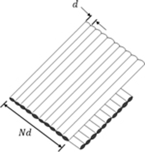
Figure 2: One diamond of braid.
The external electromagnetic field penetrates the shielding layer through three mechanisms to generate coupling on the receptor line:
1. Diffusion of the magnetic currents induced in the shield.
2. Penetration of the magnetic field through braid layer diamond-shaped holes.
3. More complex inductance phenomenon caused by overlapping of weaving wires.
The above can be described by the following formula:
| (1) |
Zis the transfer impedance, Z represents the diffusion impedance calculation formula, which describes the low frequency characteristics of electromagnetic radiation to the shielding layer, Ma formula for calculating the hole inductance, which describes the direct leakage of the magnetic field through the diamond-shaped holes in the braid, Mrepresents the formula for calculating braided inductance, which is a description of inductance phenomenon. According to the theory of [23], the vortex current of braided carries produces attenuation of transfer impedance, which is called the extra fluctuation effect M:
| (2) |
The improved transfer impedance calculation formula is:
| (3) |
According to the transfer impedance calculated by (3), the outer current of the shielding layer can be connected with the electric field of the inner layer, and the boundary conditions can be obtained. Combined with MTL to calculate crosstalk on receptor line.
III. ANALYSIS METHOD OF UNCERTAINTY QUANTIFICATION
A. Polynomial chaos expansions method
The PCE method has a solid mathematical foundation to describe the randomness of variables with different distributions [24]. The PCE method is equivalent to constructing a surrogate modeling of output variables. Any uncertain information of output variables can be obtained through the surrogate modeling, such as mean, standard deviation and probability density functions. In the construction of the surrogate modeling, PCE is usually truncated at degree p due to the consideration of calculation, and the corresponding p-degree PCE model can be expressed as:
| (4) |
where represents the corresponding coefficients of the multivariate polynomials orthonormal. The multivariate polynomials are then assembled as the tensor product of their univariate counterparts , d represents the dimension of the model input.
| (5) |
The number of polynomial coefficients in p-degree PCE model can be calculated by the following formula.
| (6) |
Next, the samples of PCE need to be sampled in the standard random space. The sampling method used in this paper is Latin hypercube design (LHD) [25]. After obtaining the samples and the response value corresponding to the samples, the PCE coefficients are calculated by the ordinary linear square (OLS) method. As follows:
| (7) |
A represents the sample matrix, represents the vector of the coefficients of the polynomial, and G represents the vector of the response value. After the polynomial coefficients of PCE is calculated according to (7), the uncertainty information of output variable can be calculated on the surrogate modeling. The mean and variance of the output variable can be expressed as:
| (8) |
| (9) |
In order to ensure accuracy and high efficiency, this paper uses the LOO method to determine the truncation degree and sample size of PCE. The process can be simply summarized as the following three steps:
1. Set the sample size to be verified and determine the truncation degree interval.
2. Use the LOO method to calculate the minimum error value of each sample size and the corresponding maximum truncation degree.
3. The error values of the minimum LOO method of each sample size are analyzed, and the optimal sample size is selected.
The error calculation formula of the LOO method is as follows:
| (10) |
where represents the response value, represents the response value calculated by the surrogate modeling constructed after removing sample points numbered i as the training set, is the expectation of the original model.
B. Global sensitivity analysis
The global sensitivity analysis can obtain the average sensitivity indexes in the entire distribution of the input variable parameters, and can also measure the effect of interaction between different input variable parameters on the uncertainty of output variables. This paper adopts Sobol’s global sensitivity analysis method based on PCE, which is based on variance decomposition and is suitable for independent input variable parameters. Because the basis functions of PCE are mutually orthogonal, Sobol’s global sensitivity decomposition can be used in (4) [26], So the first-order Sobol’s global sensitivity index based on PCE method is:
| (11) |
where c represents the coefficients of polynomials involving the only jth-dimensional variable. V represents the variance of the output variable, according to (9).
The formula of total global sensitivity index is as follows:
| (12) |
where c represents the coefficients of all polynomials involving the jth-dimensional variable.
IV. EXAMPLE APPLICATION
In this section, combined with the PCE method and Sobol’s global sensitivity analysis method based on PCE, the uncertainty quantification of the crosstalk model of braided-shielded cable is shown in Fig. 3.
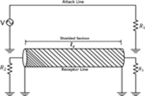
Figure 3: Braided-shielded cable model.
There are six fixed parameters in the model shown in Fig. 3. The number of carries in the braided C is 16, the number of wires in the carry N is 4, the values of all impedances are 50, and the excitation source amplitude on the attack line is set to 1V. According to the actual situation, the following eight uncertain independent parameters are set as input variable parameters of the model: lis the length of receptor line wrapped in braided layer, the distance between the attack line and the receptor line is S, the height of attack line and receptor line from the ground is h, the inner radius of the shielding layer is , the line radius of receptor line and attack line are and respectively. The distributions of input variables are as follows:
Table 1: The distribution of input variables
| Random Input Variables | Distributed and Parameters | Unit |
|---|---|---|
| l | U(3.45,3.84) | m |
| S | U(1.42e,1.57e) | m |
| h | U(1.42e,1.57e) | m |
| d | N(1.27e,(6.35e)) | m |
| r | U(8.44e,9.33e) | m |
| r | N(3.2e,(1.6e)) | m |
| r | N(3.2e,(1.6e)) | m |
| U(/18, /4) | rad |
First, its PCE surrogate modeling is constructed according to the crosstalk calculation model of braided shield cable. When selecting the sample size of PCE, usually select the number of samples twice the number of polynomials, that is, the sample size is . However, this method has its limitations in the model with high dimension and strong nonlinearity. And according to equation (6), the number of coefficients is related to the truncation degree. Using inappropriate truncation degree will not only lead to low computational efficiency, but also cause insufficient calculation accuracy. So, it is important to select the appropriate sample size and truncation degree for the PCE model. Therefore, this paper adopts the LOO method to determine the truncation degree and sample size. Set at frequency point , the sample sizes that need to be verified are 100, 200, 300, 400, and 500. The sample size of each group is analyzed by the LOO method 50 times, and the box plot is as follows:
As can be seen from Fig. 4, when the sample size is 100, 200, 300 using PCE calculation is prone to extreme outliers, and value of Inter-Quartile Range (IQR) of each sample size t is 8.510, 310, 7.710 respectively. When the sample size is 400 and 500, the IQR is 4.0810 and 4.7210 respectively, and there are no extreme outliers. At this time, the maximum truncation degree is 3. Considering the computational cost, the 3-degree truncation and the sample size of 400 should be adopted.
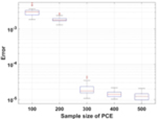
Figure 4: The box plot of error analysis of the LOO method with different sample sizes.
Second, the calculation accuracy of PCE needs to be verified. The comparison frequency band is set as [10,10] Hz, the calculation times of the MC method is 10, and the truncation degree and sample size of PCE are taken as the values verified by the LOO method. The comparison data are the near-end response voltage of the braided-shielded cable model.
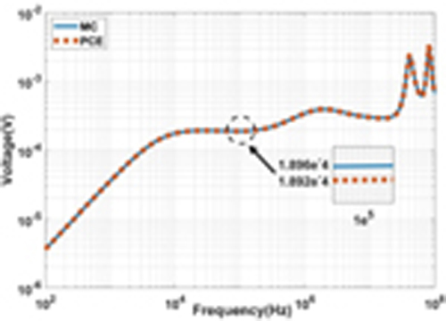
Figure 5: Comparison between the mean value of near-end response voltage computed MC and PCE.
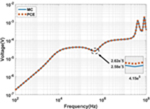
Figure 6: Comparison between the standard deviation of near-end response voltage computed MC and PCE.
As shown in Figs. 5 and 6, the standard deviation and mean value calculated by PCE are basically consistent with those calculated by MC. It can be seen that the application of the PCE method to calculate statistical moments in this model has accuracy. Then select two frequency points in [10,10] Hz, respectively, using the MC method and PCE method to calculate the probability density function at the frequency points.
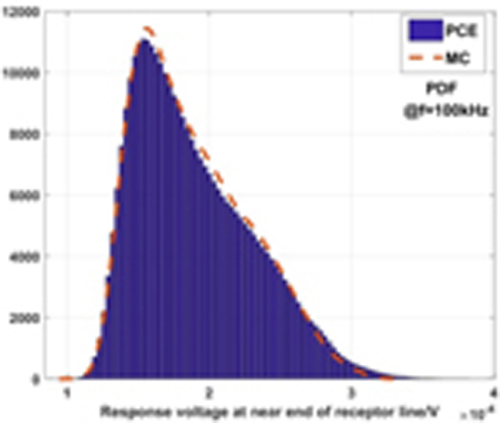
Figure 7: Comparison between the probability density functions of near-end response voltage computed by MC and PCE at 100kHz.
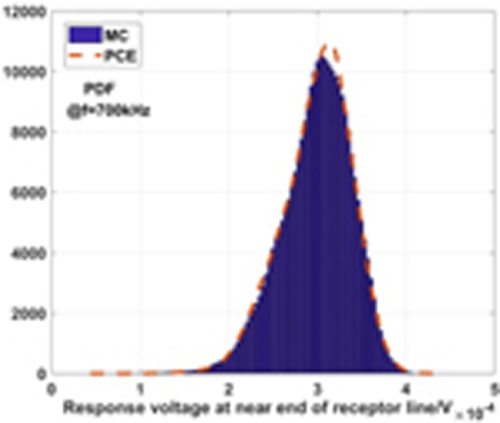
Figure 8: Comparison between the probability density functions of near-end response voltage computed by MC and PCE at 700kHz.
It can be seen from Figs. 7 and 8 that the probability density functions of the near-end crosstalk voltage calculated by the PCE and MC methods is consistent. Through the comparison and verification of mean, standard deviation and probability density function, it can be seen that the statistical characteristic parameters calculated by the PCE method and MC method are basically the same, indicating that the accuracy of uncertainty quantification of the braided-shield cable crosstalk model by PCE meets the requirements.
Finally, the efficiency of the PCE method is verified. For calculation, the MC method requires 3398 seconds on an Intel Core i5 2.4GHz, 8-GB RAM computer, while the calculation time of the PCE method is 233 seconds, which is only 6.8 % of the time required by the MC method. This shows that the PCE method is much better than the MC in computational efficiency.
Next, the Sobol’s global sensitivity analysis method based on PCE is used to analyze the global sensitivity of the eight input variables mentioned above, quantifying the influence of input variables on the model. The near-end crosstalk voltage is also selected as the comparison data, and 100kHz is set as the calculation frequency point. The results of global sensitivity analysis based on the MC method are used as comparison data.

Figure 9: The global first-order sensitivity index at 100kHz.
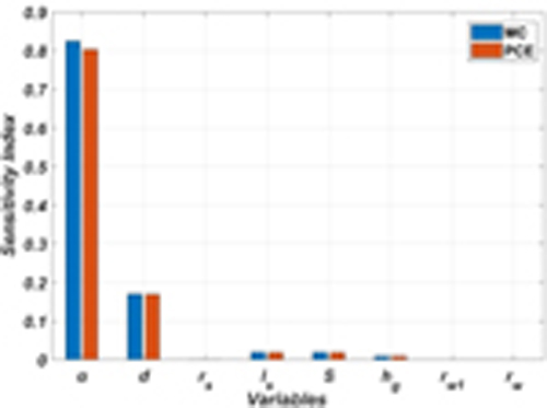
Figure 10: The global total sensitivity index at 100kHz.
Figures 9 and 10 show that the Sobol’s global sensitivity analysis method based on PCE at 100kHz is precise, compared with the MC result. It is proved that this method has accuracy in quantifying the uncertainty of the braided-shielded cable crosstalk model. In addition, it can be seen from the information given in the graphs that the weaving angle has the greatest influence at 100kHz, followed by the diameter of the braided wire d. At high frequency section, the transfer impedance consists of most of the hole inductance and braid inductance and a small part of the diffusion impedance.
In order to accurately show the influence of each input variable parameter on the model at different frequencies. Using Sobol’s global sensitivity analysis method based on PCE for each input variable in frequency band [10,10] Hz.

Figure 11: Global total sensitivity index of input variables in [10,10] Hz.
As shown in Fig. 11, when the crosstalk calculation model of braided-shielded cable is in the frequency range [10,6.3e] Hz, l and S and h have great influence on the model. Because in the low frequency state, crosstalk is mainly composed of inductive coupling, l and S and h are the three important parameters determining inductive coupling. When the frequency is greater than 6.3kHz, and d become important factors affecting the output variable, and the growth of is particularly obvious. It shows that in the process of increasing frequency, most of the crosstalk is converted from inductive coupling to capacitive coupling. The shielding layer of braided-shielded cable can greatly weaken capacitive coupling. The change of shielding layer structure parameter , rand d affects the shielding effectiveness, and then affects the crosstalk received by the receptor line. The higher the frequency, the more obvious the effect. In addition, the effects of r and r on the model are not significant.
V. CONCLUSION
In this paper, the uncertainty quantification problem of the crosstalk calculation model of braided-shield cable is studied. The model with infinite ground as a reference conductor is adopted to make the input variable parameters obey different distributions. The uncertainty of the model is quantified by the PCE method, and the relevant statistical quantities such as the mean, standard deviation and probability density functions of the near-end crosstalk voltage of the receptor line, are obtained. The computed statistical quantities using PCE were validated by the classical MC method. This proves that the PCE method can greatly improve the calculation efficiency while ensuring the calculation accuracy by simplifying the model, and realize the uncertainty quantification of the crosstalk calculation model of braided-shielded cable. Finally, the global total sensitivity index and global first-order sensitivity index of the relevant input variable parameters in the crosstalk calculation model of braided-shielded cable are calculated by combining the PCE method and the Sobol’s global sensitivity analysis method. Thus the influence degree of the relevant parameters on the braided-shielded cable crosstalk is obtained. Feasibility is also verified by the MC method. Therefore, the uncertainty quantification method and the global sensitivity analysis method proposed in this paper can provide an effective basis for the EMC design of electrical and electronic equipment with braided-shielded cables.
ACKNOWLEDGMENT
This paper is funded by the Harbin Engineering University high-level scientific research guidance special “urgent solution” research plan (3072022 QBZ0804) and the Key Laboratory of Advanced Marine Communication and Information Technology, Ministry of Industry and Information Technology, Harbin Engineering University, Harbin, China. This paper is also supported by the Shanghai Aerospace Science and Technology Innovation Fund under Grant SAST2019-002.
REFERENCES
[1] C. R. Paul, “Solution of the transmission-line equations for three conductor lines in homogeneous media,” IEEE Transactions on Electromagnetic Compatibility, vol. EMC-20, no. 1, pp. 216-222, Feb. 1978.
[2] Y. Zhao, Y. Li, and L. Zhao, “A G-shaped defected isolation wall for mutual coupling reduction between patch antenna and microstrip transmission line,” IEEE 7th Asia-Pacific Conference on Antennas and Propagation, Auckland, New Zealand, 2018.
[3] L. Gao, Q. Yu, D. Wu, T. Wang, X. Yu, Y. Chi, and T. Zhang, “Probabilistic distribution modeling of crosstalk in multi-conductor transmission lines via maximum entropy method,” IEEE Access, vol. 7, pp. 103650-103661, Jul. 2019.
[4] Q. Yu, W. Liu, K. Yang, X. Ma, and T. Wang, “Uncertainty quantification of the crosstalk in multiconductor transmission lines via degree adaptive stochastic response surface method,” Applied Computational Electromagnetics Society (ACES) Journal, vol. 36, no. 2, pp. 174-183, Feb. 2021.
[5] Y. Zhao, Y. Li, W. Shi, and W. Yu, “Mutual coupling reduction between patch antenna and microstrip transmission line by using defected isolation wall,” Applied Computational Electromagnetics Society (ACES) Journal, vol. 34, no. 1, pp. 100-106, Jan. 2019.
[6] M. Zhao, S. Xie, D. Su, and H. Sun, “Electromagnetic compatibility predesign for satellite secondary electrical power supply,” Acta Aeronautica et Astronautica Sinica, vol. 32, no. 5, pp. 849-856, May 2011.
[7] S. A. Schelkunoff, “The electromagnetic theory of coaxial transmission lines and cylindrical shields,” Bell System Technical Journal, vol. 13, no. 4, pp. 532-579, Oct. 1934.
[8] E. F. Vance, “Shielding effectiveness of braided-wire shields,” IEEE Transactions on Electromagnetic Compatibility, vol. EMC-17, no. 2, pp. 71-77, May 1975.
[9] S. Sali, “An improved model for the transfer impedance calculations of braided coaxial cables,” IEEE Transactions on Electromagnetic Compatibility, vol. 33, no. 2, pp. 139-143, May 1991.
[10] M. Tyni, “The transfer impedance of coaxial cables with braided outer conductor,” Proc. 3rd Wroclaw Symposium on Electromagnetic Compatibility, Wroclaw, Poland, pp. 410-418, 1976.
[11] T. Kley, “Optimized single-braided cable shields,” IEEE Transactions on Electromagnetic Compatibility, vol. 35, no. 1, pp. 1-9, Feb. 1993.
[12] C. R. Paul, “Transmission-line modeling of shielded wires for crosstalk prediction,” IEEE Transactions on Electromagnetic Compatibility, vol. EMC-23, no. 4, pp. 345-351, Nov. 1981.
[13] Z. Fei, H. Yi, and J. Zhou, “Crosstalk variations caused by uncertainties in three-conductor transmission lines,” Loughborough Antennas & Propagation Conference, LAPC. IEEE, Loughborough, UK, pp. 1-5, Jan. 2016.
[14] A. Tsaliovich, Cable Shielding for Electromagnetic Compatibility, Chapman and Hall, New York, 1995.
[15] P. V. Y. Jayasree, B. P. Rao, and P. Lakshman, “Analysis of shielding effectiveness of single, double and laminated shields for oblique incidence of EM waves,” Progress in Electromagnetics Research B, vol. 22, no. 22, pp. 187-202, Jan. 2010.
[16] J. L. Rotgerink, J. Verpoorte, and H. Schippers, “Uncertainties in coaxial cable transfer impedance,” IEEE Electromagnetic Compatibility Magazine, vol. 7, no. 3, pp. 83-93, Oct. 2018.
[17] M. Xu, Y. Wang., X. Li, X. Dong, H. Zhang, H. Zhao, and X. Shi, “Analysis of the influence of the structural parameters of aircraft braided-shield cable on shielding effectiveness,” IEEE Transactions on Electromagnetic Compatibility, vol. 62, no. 4, pp. 1028-1036, Jul. 2019.
[18] Y. Zhao, Y. Li, L, Zhao, V. Mordachev, and E. Sinkevich, “Equivalent circuit model for closely spaced patch antenna and microstrip line with loaded defected microstrip structure,” Cross Strait Quad-Regional Radio Science and Wireless Technology Conference, Xuzhou, China, Jul. 2018.
[19] S. Lum, M. Nakhla, and Q.-J. Zhang, “Sensitivity analysis of lossy coupled transmission lines with nonlinear terminations,” IEEE Transactions on Electromagnetic Compatibility, vol. 42, no. 4, pp. 607-615, Apr. 2002.
[20] A. Kouassi, J. Bourinet, S. Lalléchère, P. Bonnet, and M. Fogli, “Reliability and sensitivity analysis of transmission lines in a probabilistic EMC context,” IEEE Transactions on Electromagnetic Compatibility, vol. 52, no. 2, pp. 561-572, Apr. 2016.
[21] X. Liu, Y. Li, Y. Zhao, L. Zhao, V. Mordachev, and E. Sinkevich, “Equivalent circuit model of crosstalk reduction parallel transmission lines with defected microstrip structures,” Cross Strait Quad-Regional Radio Science and Wireless Technology Conference, Xuzhou, China, pp. 21-24, Jul. 2018.
[22] X. Liu, Y. Li, Y. Zhao, and L. Zhao, “Crosstalk reduction design and analysis of the planar meander transmission lines,” International Symposium on Antennas and Propagation, Busan, South Korea, pp. 23-26, Oct. 2018.
[23] F. M. Tesche, M. Lanoz, and T. Karlsson, EMC Analysis Methods and Computational Models, Wiley, New York, 1997.
[24] D. Xiu and G. Karniadakis, “Modeling uncertainty in flow simulations via generalized polynomial chaos,” Journal of Computational Physics, vol. 187, no. 1, pp. 137-167, 2003.
[25] M. D. Mckay, R. J. Beckman, and W. J. Conover, “A comparison of three methods for selecting values of input variables in the analysis of output from a computer code,” Technometrics, vol. 21, no. 2, pp. 239-245, May 1979.
[26] I. M. Sobol, “Sensitivity analysis for non-linear mathematical models,” Mathematical Modelling and Computational Experiment. vol. 1, pp. 407-414, 1993.
BIOGRAPHIES

Tianhong Tan received his B.S. degree in Electrical Engineering from Jilin University, Changchun, Jilin, China, in 2014. He is currently pursuing a Ph.D. degree in Information and Communication Engineering at Harbin Engineering University. His research interests include electromagnetic compatibility, electromagnetic simulation, and effectiveness evaluation.

Tao Jiang received his Ph.D. degree from Harbin Engineering University, Harbin, China, in 2002. Since 1994, he has been a Faculty Member of the College of Information and Communication, Harbin Engineering University, where he is currently a Professor. He was a Postdoctoral Researcher with the Research Institute of Telecommunication, Harbin Institute of Technology, Harbin, China, from 2002 to 2003, and a Visiting Scholar with the Radar Signal Processing Laboratory, National University of Singapore, from 2003 to 2004. His current research interests include radio wave propagation, complex electromagnetic system evaluation, modeling, and simulation.

Haolin Jiang received his B.S. degree from the Department of Electrical Engineering, Southwest Jiaotong University, Chengdu, Sichuan, China, in 2018 and his M. S. degree from the College of Electrical and Computer Science, Jilin Jianzhu University, Changchun, China, in 2022. He is currently pursuing a Ph.D. degree in Electrical Engineering at Jilin University. His research interests include lightning electromagnetic fields evaluation and electromagnetic compatibility.

Tianhao Wang received his B.S. degree in Electrical Engineering and his Ph.D. degree in Vehicle Engineering from Jilin University, Changchun, Jilin, China, in 2010 and 2016, respectively.
From 2016 to 2019, he was a Postdoctoral Researcher with the Department of Science and Technology of Instruments, Changchun, Jilin University. He is currently an associate professor with the College of Instrumentation and Electrical Engineering, Jilin University. His research interests include the uncertainty quantification of wireless power transfer of EVs and human electromagnetic exposure safety.

Mingjuan Cai received her Ph.D degree from the National University of Defence Technology, Changsha, China, in 2006. She works with the Naval Research Academy as a Senior Engineer. Her current research interests include electromagnetic simulation, electromagnetic compatibility and evaluation.
ACES JOURNAL, Vol. 38, No. 1, 28–35
doi: 10.13052/2023.ACES.J.380105
© 2023 River Publishers