Spiral Resonator Arrays for Misalignment Compensation in Wireless Power Transfer Systems
Nunzia Fontana1, Sami Barmada1, Marco Raugi1, Danilo Brizi2, and Agostino Monorchio2
1Department of Energy, Systems, Territory and Construction Engineering, University of Pisa, 56122, Pisa, Italy
sami.barmada@unipi.it, nunzia.fontana@unipi.it, marco.raugi@unipi.it
2Department of Information Engineering, University of Pisa, 56122, Pisa, Italy
danilo.brizi@unipi.it, agostino.monorchio@unipi.it
Submitted On: July 30, 2022; Accepted On: August 28, 2022
Abstract
In this contribution, the authors focus on the use of a metasurface (physically implemented as a 2D array of spiral resonators) as an additional component of a two-coil Wireless Power Transfer (WPT) system, with the aim of increasing the robustness to misalignment between the transmitter and the receiver coils. Resonator arrays have been proven to have a positive effect on WPT systems’ performance since they produce a focusing effect on the magnetic field; at the same time, they contribute to the reduction of the electric near field. In addition, we herein demonstrate how proper control over the metasurface’s unit cells can contribute to making a WPT system more tolerant to misalignment. In particular, the comparison between metasurfaces of different sizes (keeping the same transmitting and receiving coils) and their optimization performed to improve misalignment robustness is proved by numerical simulations.
Index Terms: Metamaterials, metasurfaces, misalignment compensation, wireless power transfer.
1 INTRODUCTION
Wireless Power Transfer (WPT) apparatuses based on resonant multi-coil systems are becoming popular devices. Especially for low-power applications, WPT can be already considered a consumer-ready product, regulated by specific international standards such as Qi. At the same time, power levels up to hundreds of kilowatts can be delivered with the same concept (but with different and more complex systems) for applications such as e-mobility. In this latter case, more aspects should be taken into account in the design phase of the WPT system, such as electromagnetic shielding and cooling issues ([1–7]).
Electromagnetic shielding is a particularly important aspect when WPT apparatuses are used to power biomedical devices or implants due to the proximity of human tissue being at its maximum. Several solutions for the reduction of magnetic field leakage are available in the literature, employing shields and passive or active coil arrangements [8–13].
More recently, some research shows that metamaterials (most commonly implemented as 2D metasurfaces) can be useful to increase power transfer efficiency by focusing the magnetic field and not being excessively prone to eddy currents [14–15]. In addition, in [16]the authors demonstrated that the use of a metasurface can also improve the system’s performance from the EMC point of view by reducing the electric near field produced by the transmitting side of a WPT system.
Nevertheless, all of the above-mentioned applications critically suffer from misalignment between the transmitter and the receiver; indeed, not perfectly aligned coils share a drastically reduced inductive mutual coupling, leading to a degradation of the global WPT performance (efficiency, amount of delivered power, flux leakage). In some commercial products, misalignment is solved by forcing the position between transmitter and receiver (i.e., in the wireless rechargeable toothbrushes). Unfortunately, this is not always a viable option, for obvious reasons. The authors demonstrated that the insertion of a metasurface between driving and receiving coils also mitigates the efficiency drop problem that arises from misalignment in a common inductive WPT system [17]. Other research groups proposed a tunable active version of the resonator’s matrix, with the same purposes [18–19].
In this contribution, a study on a metasurface, in which each resonator is passive, is performed, with the goal of addressing the misalignment recovering purpose.
The analysis is conducted both by employing full wave electromagnetic software (for the system characterization) together with a circuit simulator. Different optimization procedures are followed to find the best values of the capacitors that are connected to each single resonator of the metasurface
The practical implementation of the proposed compensation is case-dependent. If the geometrical structure of the system allows misalignment only along one direction, a direct solution without active devices, taking into account the results shown below, is feasible. In case the misalignment is completely not predictable, then the use of varicaps is needed.
The results obtained (and shown in this paper) demonstrate that the use of passive metasurfaces for misalignment compensation is possible, and constitutes a basis for the designers, evidencing how the size of the metasurface affects the performance of the system.
2 WORKING PRINCIPLE
The WPT configuration object of this study is a commonly used magnetic resonance-based system, in which a compensation network is present both at the transmitter and receiver sides; the compensation network makes the system resonant at a specific working frequency.
Instead of adopting additional repeater coils (typically one or two), a metasurface is specifically designed. Typically, all the metasurface elements are tuned at the same operating frequency of the two main coils (transmitter and receiver); moreover, the metasurface is usually positioned in between the two principal coils, at a specific distance from one of them, depending on the specific purpose it is designed for.
The authors in [16] demonstrated that an optimally designed metasurface, located in close proximity to the transmitter, reduces the electric field that could reach values above the limits recommended by the ICNIRP guidelines. In the same study, the authors performed an analysis of the geometrical characteristics of the metasurface, identifying, for this particular case, the optimal number of elements. This optimum allowed us to achieve the desired shielding level while maintaining an acceptable decrease in the performance due to increased losses in the metasurface itself.
By starting from this study, Fig. 1 shows the complete system after the design process, leading to an optimal configuration of the metasurface, i.e., a matrix of resonators. The system has been designed and prototyped, showing that a real shielding effect can be achieved [16].
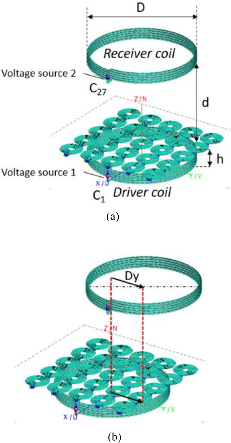
Figure 1: Geometry of the proposed WPT system: (a) coaxial; (b) with a Dy misalignment along y axis.
Figure 1, on the contrary, shows the same configuration but with the presence of a misalignment (indicated by Dy) between the transmitting and receiving coils. As anticipated, a misalignment between transmitter and receiver in resonant WPT systems reduces the coupling coefficient, hence both the transmitted power and the efficiency. There are various techniques to reduce the misalignment effect on the performance, ranging from mechanical constraints to a closed loop communication between transmitter and receiver (implemented by the measurement of sensitive quantities such as currents, for instance), that gives feedback to the operator relative to the misalignment quantity.
In this contribution, the authors focus on the use of a passive metasurface as the means to recover the misalignment between transmitter and receiver. The advantage of this choice relies on the fact that no complex communication link should be created; in addition, a passive metasurface, if compared to an active device, avoids the presence of complex networks for changing loading capacitors values. In [17], only a metasurface of specific dimensions was considered (coincident with the one shown in Fig. 1); in this case, the side of the square metasurface is coincident with the diameter of the transmitter and receiver coils. As demonstrated in [16], this solution reduces joule losses (that are introduced in the case of larger metasurfaces, i.e., with a higher number of resonators), but once one of the two coils is moved, there is a significant part of its surface that is projected outside the metasurface. This led the authors to investigate the possibility of employing larger metasurfaces that, despite being characterized by higher power losses, can reduce performance degradation in case of misalignment.
For this reason, the performances of metasurfaces of different dimensions are compared, and a procedure for the optimization of the loading capacitors’ value is performed.
3 NUMERICAL METHODS
The CAD model of the system, as shown in Fig. 1, has been created with commercial electromagnetic software (Feko suite, Altair, Troy, MI, USA) based on the Method of Moments. In the full wave model, each coil of the WPT system (including the unit cells of the meta surface) terminates in a lumped port. The ports of the metasurface elements are, in turn, closed on a lumped capacitor; the port of the driver coil (transmitter) is terminated with a series connection between the generator and the proper resonant capacitor, while the port of the receiver is terminated with the resonant capacitor and resistive load.
A single full-wave simulation (for a given operation frequency) allows the characterization of the system as an N-port entity, represented by using the S or Z parameters matrix. In this particular case, ports are relative to the lumped loading capacitances of the metasurface unit cells (used to impose resonance of each resonator at the selected frequency) while the 2 remaining ports (labeled as Port 1 and Port 2) are relative to the transmitter and receiver, represented in Fig. 2 as a generator and a resistive load, respectively.
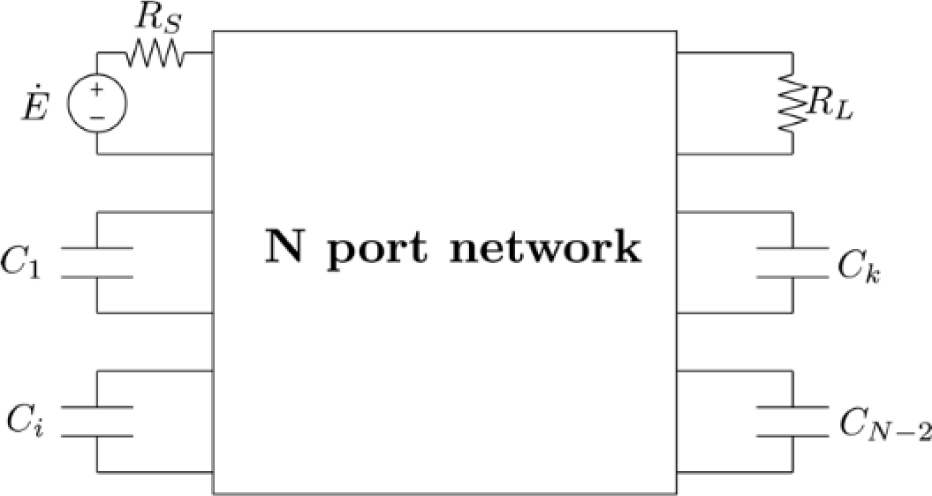
Figure 2: N-port circuit representation of the proposed WPT system: N-2 ports are dedicated to the capacitive loads of the metasurface unit cells, while the first two are relative to the transmitting and receiving coils.
The rationale behind the choice of finding an equivalent circuit stands in the fact that we are not interested in the field distribution, but only in the performances of the system in terms of currents and voltages. Indeed, the efficiency of the system is calculated as:
| (1) |
Equation (1) applies to the N-port circuit represented in Fig. 2. A more synthetic representation would be the usual 2-port circuit, easily obtainable by the same full-wave model and not considering the capacitors as external ports, as in the following expression.
| (2) |
where:
| (3) |
While this synthetic representation would anyway allow the evaluation of the efficiency as in equations (1) and (2) and give more insight due to the explicit presence of the impedance parameters, it will not allow for an optimization of the capacitances to achieve misalignment compensation.
The calculations on the N-port circuit have been carried out by using the Keysight Advanced Design System (ADS) software, according to the following steps:
a. evaluation of the performance in case of perfect alignment between transmitter and receiver, with the capacitance value optimized to a specific single nominal value;
b. evaluation of the performances in case of misalignment, with the capacitances set to the nominal value (as in the previous simulation);
c. optimization the capacitances, with the goal of maximizing the efficiency level of the system in presence of misalignment.
The optimization procedure used in this paper is directly implemented in the software ADS; the number of parameters to be optimized is relatively high (the capacitance of each lumped element present in the metasurface, ranging from 25 to 81 in the following results), and the fitness function in equation (2) is relatively flat with a high number of local minima. However, the obtained results are sound and small differences in the value of the capacitances (obtained in different optimization runs) do not significantly affect the results. The authors also performed a set of Montecarlo analysis(not shown here for the sake of conciseness) to verify how the system is robust towards capacitances variation due to tolerance, and the outcome confirm the validity of the results shown below.
4 RESULTS
The numerical cases reported in this section have been obtained by employing the commercial tools mentioned before; in addition, the system named “test case #1” has been also implemented in a lab experiment, as described below. On the contrary, the test cases with metasurfaces of larger dimensions have been implemented only numerically. All the simulations results are characterized by a voltage source of amplitude , since the goal of the analysis is to validate the working principle of the proposal. Both the generator and the load resistances ( and respectively) have been chosen equal to 50.
Table 1: Geometrical quantities of the system
| Quantity | Value |
|---|---|
| Tx diameter | |
| Rx diameter | |
| Operating frequency | |
| Slab thickness | |
| Unit cell conductor diameter | |
| Unit cell average diameter | |
| Slab distance from the transmitter | 1.4cm |
| Number of resonators |
4.1 Test case #1: metasurface and coils characterized by the same dimension
The first results are relative to the experimental setup proposed in [16], in which the metasurface is a square slab with the side coincident with the diameter of the transmitting and receiving coils, fabricated with a 3D printing process. The slab was engraved with spiral grooves following the unit cells profile thanks to a commercial 3D printer. Table 1 shows the main geometrical quantities, while Fig. 3 shows the system during the experiments performed and described in [16].

Figure 3: Experimental setup. The metasurface is placed few millimeters above the driving coil.
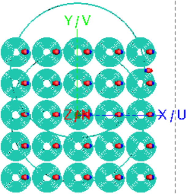
Figure 4: Representation of the WPT system with the misaligned receiver.
In this nominal case, the optimal value of the capacitances that leads to the higher efficiency level is . A full-wave simulation with all the unit cells tuned with has been carried out to obtain the efficiency (as defined in equations (1) - (3)) and the power delivered to the load, respectively , .
Later, the same simulation has been performed in the case of a misalignment of the receiver, where (see Fig. 4).
In the misaligned configuration, the performances are summarized by efficiency and power as , , which is lower with respect to the previous nominal case.
To improve the performances in case of misalignment, different values of the tuning capacitors are considered; the optimization procedure has now been set to optimize every single capacitance. This result in new values of efficiency and power to the load, respectively , .
As it is evident from the previous values, the new capacitances allow a partial recovery both of the efficiency and the power delivery levels.
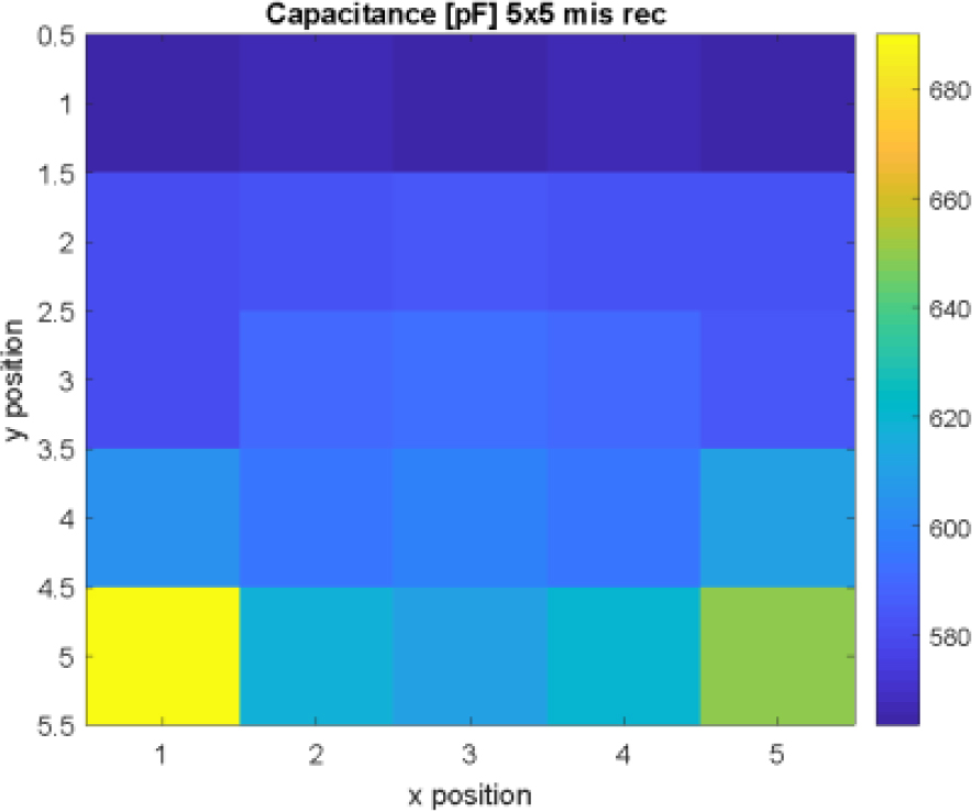
Figure 5: Values of the tuning capacitors in the metasurface with 55 elements.
Figure 5 shows a colormap matrix in which the values of the capacitances are associated with their position in the metasurface. At a first glance, it can be easily noted that in areas of the metasurface not covered by the misaligned receiver, the capacitance assumes a higher value, i.e., the single resonator is characterized by a higher inductive behavior.
4.2 Test case #2: metasurface side larger than coils diameters ( elements)
In this second case, the authors simulated the presence of a slab of wider dimension, i.e., whose side is larger than the transmitting and receiving coil diameters. The metasurface is now composed of a matrix of the same identical spiral resonators, with the aim of investigating the possibility of an increased capability misalignment compensation. The new test case is shown in Fig. 6, both in the aligned and in the misaligned configuration.
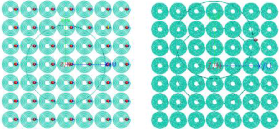
Figure 6: WPT system with metasurface, with the receiver in aligned position (left) and misaligned position (right).
In the nominal case, the optimal value of the capacitances that leads to the higher efficiency is ; with all the unit cells tuned with , the efficiency and the power delivered to the load, respectively, are , .
The simulation has been replicated in presence of the same misalignment (see Fig. 6). It is worth noticing that, in this case, the slab 77 (characterized by increased size) covers both the transmitter and the receiver also in the misaligned configuration, leading to a potentially higher capability of misalignment recovery.
In this case, the performances are summarized by efficiency and power as , , that are lower with respect to the previous nominal case. At the same time, a newsworthy result is derived: the performance decrease is lower if compared to the previous case.
The same optimization procedure has been performed in this case, resulting in new values of the selected performance parameters, respectively , .
As it is evident from the previous values, the new capacitances allow an almost complete recovery of the efficiency also in the misaligned configuration.
Figure 7 shows a colormap matrix in which the values of the capacitances are associated with their position in the metasurface. Again, it is easy to verify that in the section of the metasurface not covered by the misaligned receiver, the capacitance assumes a higher value.
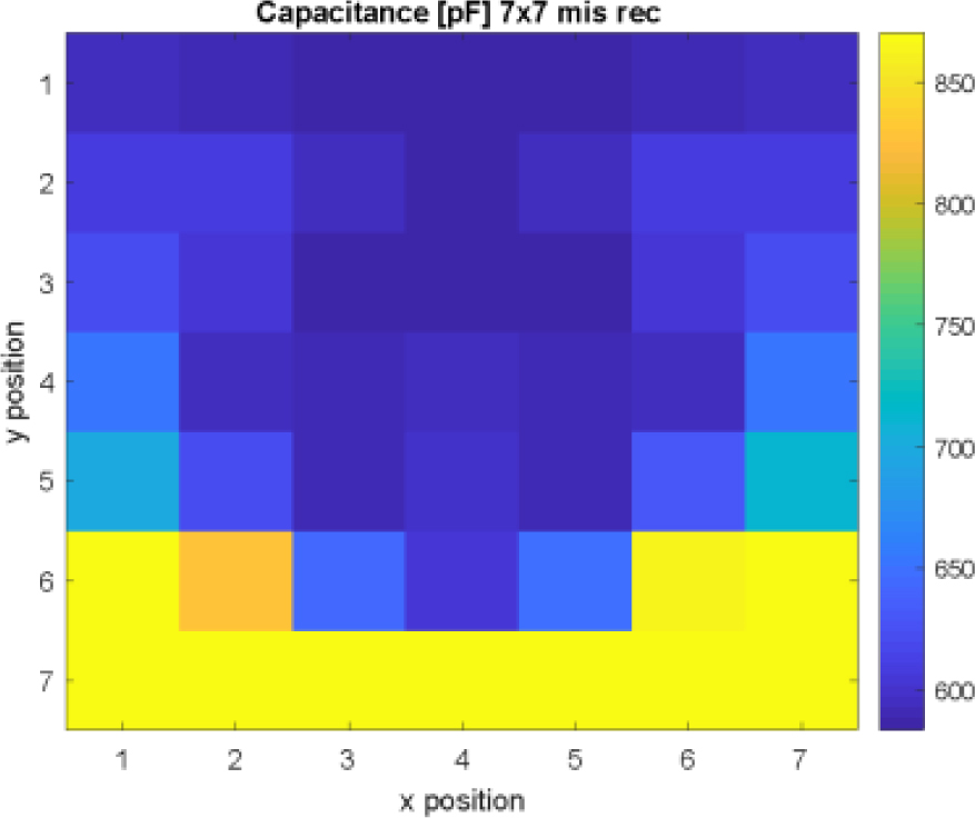
Figure 7: Values of the tuning capacitors in the metasurface with 77 elements.
4.3 Test case #3: metasurface side larger than coils diameters ( elements)
In the final case shown in this paper, the authors simulated the presence of a slab of an even wider dimension, i.e., a matrix of resonators. The new test case is shown in Fig. 8, both in the aligned and in the misaligned configuration.
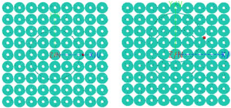
Figure 8: WPT system with metasurface, with the receiver in aligned position (left) and misaligned position (right).
In the nominal case, the optimal value of the capacitances that leads to the higher efficiency is; with all resonators tuned with the efficiency and the power delivered to the load, respectively are , .
The same simulations have been performed in presence of the same misalignment (see Fig. 8). In this case, the performances are summarized by efficiency and power as , , which are lower with respect to the previous nominal case. In the present case, an already observed and interesting trend is confirmed: the performance decrease is lower if compared to the previous cases.
The same optimization procedure has been performed in this case, resulting in new values of the selected performance parameters, respectively , .

Figure 9: Values of the tuning capacitors in the metasurface with 99 elements.
In this case, the recovery in terms of efficiency is practically total, even though it is performed at the cost of a lower power delivered to the load.
Figure 9 shows a colormap matrix in which the values of the capacitances are associated with their position in the metasurface. Again, it is easy to verify that in the section of the metasurface not covered by the misaligned receiver, the capacitance assumes a higher value, suggesting a systematic behavior that the metasurface needs to present with the aim of compensating for the misalignment introduction in a specific direction, thus confirming what already guess by the authors in [17].
4.4 General comments
The following overall trend can be evidenced:
• The nominal capacitance capable of making the whole system resonate at slowly increases with the dimension of the metasurface. This is due to the known frequency shifting phenomenon caused by the mutual coupling between all the metasurface elements. The larger the metasurface, the higher the mutual coupling contribution coming from the surrounding cells.
• An increase of the dimension of the metasurface above a certain limit, causes a reduction of the efficiency, because of the joule losses in the high-number resonators. Moreover, the unit cells far from the center of the Tx or Rx coils have practically no effect on the field focusing.
• An increase in the dimension of the metasurface allows a lower performance degradation in case of misalignment.
• An increase in the dimension of the metasurface allows a stronger efficiency recovery when the values of the capacitances are properly selected.
• The inductive behavior of the single resonators appearing in case of misalignment (of the areas of the metasurface not covered by the misaligned receiver) can be explained by the need of reducing the current in these particular resonators to redistribute the magnetic field spatial configuration, that is achieved with an increase of the equivalent inductance.
Considering all the previous points, from the economical point of view, the inclusion of a passive metasurface in a WPT system does not significantly affect its overall cost. In case the metasurface is implemented with the use of varicaps, the main cost increase would be relative to the varicaps control circuit, but in the authors’ opinion, it will not anyway be comparable with the cost of the high-frequency AC power supply.
5 CONCLUSION
In this paper the authors investigated the use of passive metasurfaces as a tool for the compensation of misalignment in wireless power transfer systems. Starting from a system implemented in the lab, the authors have simulated metasurfaces of different dimensions and verified that, when they are properly designed, they can contribute to the reduction and compensation of performance degradation, in case a perfect placement of the transmitter and receiver coil cannot be guaranteed.
REFERENCES
[1] A. P. Sample, D. A. Meyer, and J. R. Smith, “Analysis experimental results, and range adaptation of magnetically coupled resonators for wireless power transfer,” IEEE Trans. Ind. Electron., vol. 58, no. 2, pp. 544-554, Feb. 2011.
[2] G. Wang, W. Liu, M. Sivaprakasam, and G. A. Kendir, “Design and analysis of an adaptive transcutaneous power telemetry for biomedical implants,” IEEE Trans. Circuits Syst. I, Reg. Papers, vol. 52, no. 10, pp. 2109-2117, Oct. 2005.
[3] A. K. RamRakhyani, S. Mirabbasi, and M. Chiao, “Design and optimization of resonance-based efficient wireless power delivery systems for biomedical implants,” IEEE Trans. Biomed. Circuits Syst., vol. 5, no. 1, pp. 48-63, Feb. 2011.
[4] C.-S. Wang, O. H. Stielau, and G. A. Covic, “Design considerations for a contactless electric vehicle battery charger,” IEEE Trans. Ind. Electron., vol. 52, no. 5, pp. 1308-1314, Oct. 2005.
[5] M. Bertoluzzo, P. Di Barba, M. Forzan, M. E. Mognaschi, and E. Sieni, “Multiobjective optimization of compensation networks for wireless power transfer systems,” COMPEL - The International Journal for Computation and Mathematics in Electrical and Electronic Engineering, vol. 41, no. 2, pp. 674-689, 2022.
[6] M. Song, P. Belov, and P. Kapitanova, “Wireless power transfer inspired by the modern trends in electromagnetics,” Appl. Phys. Rev., vol. 4, no. 2, Art. no. 021102, Jun. 2017.
[7] J. Shin, S. Shin, Y. Kim, S. Ahn, S. Lee, G. Jung, S.-J. Jeon, and D. H. Cho, “Design and implementation of shaped magnetic-resonance- based wireless power transfer system for roadway-powered moving electric vehicles,” IEEE Trans. Ind. Electron., vol. 61, no. 3, pp. 1179-1192, Mar. 2014.
[8] I. Lee, N. Kim, I. Cho, and I. Hong, “Design of a patterned soft magnetic structure to reduce magnetic flux leakage of magnetic induction wireless power transfer systems,” IEEE Trans. Electromagn. Compat., vol. 59, no. 6, pp. 1856-1863, Dec. 2017.
[9] M. Mohammad, E. T. Wodajo, S. Choi, and M. E. Elbuluk, “Modeling and design of passive shield to limit EMF emission and to minimize shield loss in unipolar wireless charging system for EV,” IEEE Trans. Power Electron., vol. 34, no. 12, pp. 12235-12245, Dec. 2019.
[10] S. Lee, D.-H. Kim, Y. Cho, H. Kim, C. Song, S. Jeong, J. Song, G. Park, S. Hong, J. Park, K. Cho, H. Lee, C. Seo, S. Ahn, and J. Kim, “Low leakage electromagnetic field level and high efficiency using a novel hybrid loop-array design for wireless high power transfer system,” IEEE Trans. Ind. Electron, vol. 66, no. 6, pp. 4356-4367, Jun. 2019.
[11] Q. Zhu, Y. Zhang, Y. Guo, C. Liao, L. Wang, and L. Wang, “Null-coupled electromagnetic field canceling coil for wireless power transfer system,” IEEE Trans. Transport. Electrific., vol. 3, no. 2, pp. 464-473, Jun. 2017.
[12] M. Bertoluzzo, P. Di Barba, M. Forzan, M. E. Mognaschi, and E. Sieni, “Field models for the electromagnetic compatibility of wireless power transfer systems for electric vehicles,” Engineering Computations, vol. 39, no. 7, pp. 2802-2819,2022.
[13] T. Campi, S. Cruciani, F. Maradei, and M. Feliziani, “Magnetic field mitigation by multicoil active shielding in electric vehicles equipped with wireless power charging system,” in IEEE Transactions on Electromagnetic Compatibility, vol. 62, no. 4, pp. 1398-1405, doi: 10.1109/TEMC.2020.2988463, Aug. 2020.
[14] Y. Cho, S. Lee, D.-H. Kim, H. Kim, C. Song, S. Kong, and J. Park, “Thin hybrid metamaterial slab with negative and zero permeability for high efficiency and low electromagnetic field in wireless power transfer systems,” IEEE Trans. Electromagn. Compat., vol. 60, no. 4, pp. 1001-1009, Aug.2018.
[15] Y. Cho, J. J. Kim, D.-H. Kim; S. Lee, H. Kim, and C. Song, “Thin PCB-type metamaterials for improved efficiency and reduced EMF leakage in wireless power transfer systems,” IEEE Trans. Microw. Theory Techn., vol. 64, no. 2, pp. 353-364, Feb. 2016.
[16] D. Brizi, N. Fontana, M. Tucci, S. Barmada, and A. Monorchio, “A spiral resonators passive array for inductive wireless power transfer applications with low exposure to near electric field,” in IEEE Transactions on Electromagnetic Compatibility, vol. 62, no. 4, pp. 1312-1322, doi: 10.1109/TEMC.2020.2991123, Aug. 2020.
[17] N. Fontana, D. Brizi, S. Barmada, M. Raugi, and A. Monorchio, “Optimization and robustness analysis of a spiral resonators array for misalignment recovering purposes in WPT systems,” 2021 XXXIVth General Assembly and Scientific Symposium of the International Union of Radio Science (URSI GASS), pp. 1-3, 2021.
[18] A. L. A. K. Ranaweera, C. A. Moscoso, and J.-W. Lee, “Anisotropic metamaterial for efficiency enhancement of mid-range wireless power transfer under coil misalignment,” J. Phys. D: Appl. Phys., vol. 48, pp. 8, 2015, doi: 10.1088/0022-3727/48/45/455104.
[19] H. N. Bui, T. S. Pham, J.-S. Kim, and J.-W. Lee, “Field-focused reconfigurable magnetic metamaterial for wireless power transfer and propulsion of an untethered microrobot,” Journal of Magnetism and Magnetic Materials, vol. 494, pp. 165778, ISSN 0304-8853, 2020, https://doi.org/10.1016/j.jmmm.2019.165778.
BIOGRAPHIES

Nunzia Fontana received an M. Sc. (summa cum laude) in telecommunications engineering and a Ph.D. in remote sensing from the University of Pisa, Italy, in 2008 and in 2012, respectively. She is an Associate Professor of Electrical Engineering with the Department of Energy, Systems, Territory and Construction Engineering, University of Pisa. Her research interests include wireless power transfer; antennas, impedance matching networks design, prototyping, and RF testing, radio frequency coils design for magnetic resonance and RF testing, and bio-electromagnetics. Her research activities have been published in several international scientific journals and in a number of international conference proceedings. She is IEEE Senior Member and Applied Computational Electromagnetics Society (ACES) Member. Prof. Fontana serves as an Associate Editor forACES Journal.

Sami Barmada received M.S. and Ph.D. degrees in electrical engineering from the University of Pisa, Italy, in 1995 and 2001, respectively. He is currently a Full Professor with the Department of Energy and System Engineering, University of Pisa. He is an author and co-author of more than 180 papers in international journals and indexed conferences. His research interests include applied electromagnetics, electromagnetic fields calculation, power line communications, wireless power transfer devices, and nondestructive testing. Prof. Barmada is an Applied Computational Electromagnetics Society (ACES) Fellow and he served as ACES President from 2015 to 2017. He is a member of the International Steering Committee of the CEFC Conference and he has been the General Chairman and Technical Program Chairman of numerous international conferences.

Marco Raugi is a Professor of Electrical Engineering at the Department of Energy, Systems, Territory, and Construction Engineering. He graduated in Electronic Engineering from the University of Pisa in 1985 and received his Ph.D. in Electrical Engineering from the university in 1990. Main Research Topics are Computational Electromagnetics, Nondestructive testing magnetostrictive sensors, and Sustainable Energy Communities. The research activity of Professor Marco Raugi has produced more than 250 publications in international journals and conferences. The achievements of his studies have been acknowledged by several invitations to international conferences as session chairman or chairman of the editorial board and as the author of invited speeches and tutorials. He is currently the Vice-Rector for Applied Research and Technology Transfer of the University of Pisa, Head of the Interdepartmental Center for Research on Energy for Sustainable Development (CIRESS), and Chair Holder of the UNESCO/UNITWIN Chair “Sustainable Energy Communities”.

Danilo Brizi was born in Viterbo, Italy, in 1992. He received an M.S. Laurea degree in biomedical engineering and a Ph.D. degree in information engineering (both summa cum laude) from the University of Pisa in 2016 and 2020, respectively. He is currently an Assistant Professor at the same university. His research interests include electromagnetic metasurfaces, MRI filter design, and wireless power transfer applications.

Agostino Monorchio is a Full Professor with the University of Pisa, Pisa, Italy. He received a Laurea degree in electronics engineering and the Ph.D. degree in methods and technologies for environmental monitoring from the University of Pisa, Pisa, Italy, in 1991 and 1994, respectively. He spent several research periods at the Electromagnetic Communication Laboratory, Pennsylvania State University, State College, PA, USA, both as a recipient of a scholarship (Fellowship Award) of the Summa Foundation, Albuquerque, NM, USA, and in the framework of CNR-NATO Senior Fellowship program. He has carried out considerable research activity and technical consultancy to national, EU, and U.S. industries, coordinating, as Principal Scientific Investigator, a large number of national and European researchprojects.
He is active in a number of areas including computational electromagnetics, microwave metamaterials, radio propagation for wireless systems, the design and miniaturization of antennas and electromagnetic compatibility, and biomedical applications. The activity is mainly carried out at the Microwave and Radiation Laboratory (www.mrlab.it), Department of Information Engineering, University of Pisa, together with a large group of Ph.D. students, Postdocs, and Research Associates. His research results have been published in more than 130 journal papers and book chapters, and more than 200 communications at international and national conferences. He is a co-author of fourpatents.
Prof. Monorchio is a member of the RaSS National Laboratory, Consorzio Nazionale Interuniversitario per le Telecomunicazioni, Parma, Italy, and since 2010 he has been with the Pisa Section of INFN, the National Institute of Nuclear Physics. He was elevated to a Fellow by the IEEE for his contributions to computational electromagnetics and for the application of frequency selective surfaces in metamaterials in 2012.
ACES JOURNAL, Vol. 37, No. 7, 765–773.
doi: 10.13052/2022.ACES.J.370703
© 2022 River Publishers