A Topological Charge Continuously Tunable Orbital Angular Momentum (OAM) Electromagnetic Wave Generation Method Based on Fixed-length Delay Line Mixing Circuit
Yuliang Zhou, Xiaona Li, Kaiyuan Yao, Yong Mao Huang and Haiyan Jin
1School of Aeronautics and Astronautics, University of Electronic Science and Technology of China, Chengdu, China.
uestcjhy@uestc.edu.cn
2School of Electrical and Electronic Information, Xihua University, Chengdu, China
Submitted On: August 4, 2022; Accepted On: September 26, 2022
ABSTRACT
To overcome the drawback of complex structure and high cost attributed from the utilization of phase shifters to generate OAM in the conventional schemes, this paper proposes a new method for generating OAM based on a fixed delay line. By deriving the proposed system with fixed delay line theoretically, the relationship between the frequency of the input signal on the delay line and the topological charge of the OAM is obtained, and the topological charge of the generated OAM can be controlled by controlling the frequency. Furthermore, this paper proposes a vortex beam pointing control method based on phased array scanning, so as to realize the beam steering of OAM. It is then verified by using electromagnetic simulation, and the simulation results show that the proposed method is feasible. The proposed method not only has the advantages of simple structure and low cost, but also can generate OAM with continuously adjustable topological charge by controlling the frequency, which has the functions of topological charge reconstruction and dynamic adjustment.
Index Terms: beam steering, continuous topological charge, delay line, vortex electromagnetic waves.
I. INTRODUCTION
In recent years, to increase the channel capacity and spectrum utilization, and to make the communication network more reliable and secure, the Orbital Angular Momentum technology [1, 2] has been introduced. The electromagnetic wave-carrying OAM is called vortex electromagnetic wave, and its wavefront phase is different from the plane structure of traditional plane wave due to carrying orbital angular momentum [3]. This feature provides a new direction for increasing information transmission capacity and improving spectral efficiency [4]. It is mentioned in [5] that vortex electromagnetic waves carry information about geometric shapes and material properties. Additionally, the orbital angular momentum multiplexing technology of vortex electromagnetic waves has extremely efficient frequency utilization and anti-interference ability [6], and has good application prospects. The research of vortex electromagnetic waves in optics has been relatively mature. Compared with the great role played by vortex electromagnetic waves in the field of optics, it cannot fully play the role of vortex electromagnetic waves in the field of wireless communication [7].
According to the existing literature, it can be determined that the main methods of generating orbital angular momentum are: helical reflector structure [8], transmission helical structure [9], transmission grating structure [10], and array antenna [11, 12]. At present, the method of using array antennas to excite vortex electromagnetic waves has been widely studied [13], but due to the high cost of phase-shifting devices in the array, it is not conducive to mass production and manufacturing. To reduce the cost of phased arrays that generate vortex electromagnetic waves, international researchers have adopted a variety of methods to reduce the cost of phased arrays, mainly in the following aspects: improving phase-shifting devices [14], reducing the cost of phase-shifters number [15], and make a reasonable array [16], so the related theory of vortex electromagnetic wave is still worthy of in-depth study.
II. GENERATION OF VORTEX ELECTROMAGNETIC WAVES BASED ON A FIXED DELAY LINE
The schematic diagram of the vortex electromagnetic wave generated by the uniform circular array is shown in Fig. 1 [17]. Based on the method of fixed delay line, the phase offset between each array element is controlled, so as to generate continuous topological charge OAM by changing the frequency. However, this approach causes the beam’s transmit frequency to vary with its topological charge. Since most communication systems require a constant transmit frequency, a heterodyne mixer can be added to each antenna element so that the radio frequency (RF) transmit signal appearing at each antenna element is the result of mixing an intermediate frequency (IF) signal and a local oscillator (LO) signal.
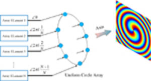
Figure 1: Schematic diagram of vortex electromagnetic wave generated by uniform circular array.
Based on the basic principle of the above-mentioned uniform circular array to excite vortex electromagnetic waves, this paper proposes a phase shifter-free vortex electromagnetic wave generation system, which includes a LO signal source and an IF signal source. The output end of the LO signal source is connected to the delay line, which is respectively connected to the input end of the heterodyne mixer. The other input terminal of each heterodyne mixer is connected to the IF signal source. The output terminals of each heterodyne mixer are connected to an one antenna unit and the antenna units are arranged in a circle at equal intervals. The specific schematic diagram is shown in Fig. 2. From Fig. 2, the specific method of exciting the vortex electromagnetic wave is based on the determined antenna element number and the initial vortex electromagnetic wave modulus. The phase shift of the LO signal entering each heterodyne mixer is determined, so as to obtain the length of each delay line. The heterodyne mixer is connected with the LO signal source through the delay line; the LO signal and the IF signal entering into it are mixed through the heterodyne mixer, then each mixed frequency signal is mixed through the antenna unit. The signal is transmitted to complete the generation of the vortex electromagnetic wave. Finally, the vortex electromagnetic wave with continuous topological charge can be obtained by changing the frequency of the LO signal. Accordingly, the relationship between the frequency of the LO signal and the topological charge of the generated vortex electromagnetic wave canbe derived.
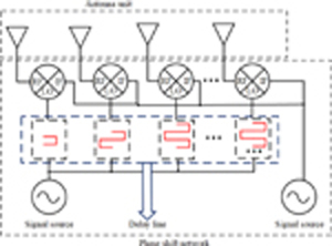
Figure 2: Phase-shifting network structure based on delay line.
Set the IF signal and the LO signal:
| (1) |
| (2) |
It is known after mixing the two signals that if the frequency of the LO signal increases by , to ensure that the frequency of the output RF signal does not change after mixing, the frequency of the IF signal needs to be reduced by . Assuming the length of the delay line is , according to the phase shift constant of the delay line, the phase shift it can produce is:
| (3) |
It can be seen from Fig. 2 that if the delay line acts on the LO signal source, the LO will add a phase shift generated by the delay line and combined with Equation (3), namely:
| (4) |
The initial phase of the signal source can be set to 0. Assuming that the number of antenna elements is , to obtain a vortex electromagnetic wave with a topological charge of , the phase offset required by the mth antenna element is:
| (5) |
Then according to Equations (3) and (5), the length of the delay line corresponding to the mth antenna unit can be calculated as:
| (6) |
where is the angular frequency of the LO signal entering the m th delay line, is the dielectric constant of the m th delay line, and is the permeability of the m th delay line.
The above derivation process and conclusion are under the premise that the number of array elments of the antenna array is large enough, but the number of array elements of the antenna array is an important factor affecting the topological charge of the vortex electromagnetic wave. Although the topological charge number of vortex electromagnetic waves can take any integer value in theory, the maximum number of topological charges that can be generated is determined by the number of array elements of the antenna array that generates vortex electromagnetic waves compared with conventional arrays. The range of topological charges that can be generated by a circular phased array is:
| (7) |
where represents the number of elements of the antenna array.When the topological charge is greater than or equal to , there will be no pure helical phase wavefront beam generation, which means that no perfect vortex electromagnetic wave can be obtained.
It can be seen from the above derivation that when the length of delay line is fixed, the number of OAM topological charge increases by 1 for every doubling of the signal frequency applied on the delay line. Within the range of OAM topological charges allowed by the number of array elements, the structure can produce OAM with tunable continuous topological charges only by adjusting the frequency.
Based on the uniform circular array with radius A, the number of array elements M is selected as 8, working frequencies of 10 GHz and 4 GHz were selected to conduct electromagnetic simulation. The simulation results are shown in Table 1.
Table 1: At different frequencies, OAM with being 1, 2, and 3 corresponds to 3-D Pattern, Amplitude, and Phase diagrams
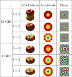
It can be seen from Table 1 that the phase diagrams of electromagnetic waves generated by this method all present the shape of helical phase wavefront, which is a typical feature of vortex electromagnetic waves.The electromagnetic simulation results show that with the increase of the topological charge number, the generated side-lobe of the OAM pattern increases and the zero-depth region increases, indicating that the energy is gradually dispersed with the increase of the topological charge number. Additionally, according to the degree of color alternation, the phase change values of the vortex electromagnetic wave can be obtained respectively as and , corresponding to the topological charges of OAM being 1, 2 and 3. It further proves the feasibility of the OAM generation method without phase shifter proposed in this paper, and that the method is suitable for different working frequencies.
Table 2: Phase distribution of radiation field under different array radius and frequency when is 8
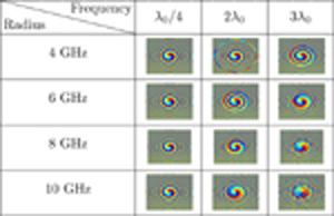
The above simulation results show that this method can generate relatively ideal vortex electromagnetic waves. Next, the topological charge of the generated vortex electromagnetic waves is fixed at 1, and the array radius and operating frequency parameters are modified. Phase diagrams of vortex electromagnetic waves corresponding to different operating frequencies. Table 2 shows the phase diagram results based on the 8-element uniform circular array. Where, is the corresponding wavelength when the operating frequency is 10GHz. As can be seen from the table, the array radius and operating frequency will have a certain impact on the OAM. For a fixed frequency, as the array radius increases, the phase image of the OAM begins to appear phase aliasing; for a fixed radius, as the operating frequency increases, the phase image of the OAM begins to appear phase aliasing. This is because the side lobes of the radiation pattern of the uniform circular array increase, and the vortex electromagnetic wave radiation field is in the state of superposition of the main lobe radiation and the side lobe radiation. When phase aliasing occurs, the vortex electromagnetic wave has not only one OAM mode, but also a superposition of different OAM modes in the main lobe and side lobes. [18] presents an algorithm for vortex beam optimization design that might be needed to optimize the sidelobe level of the vortex beam.
III. GENERATION OF VORTEX ELECTROMAGNETIC WAVES WITH ARBITRARY ORIENTATION BASED ON PHASED ARRAY
To generate a vortex electromagnetic wave with a topological charge number , the excitation phase of the array element needs an additional phase , which can be expressed as:
| (8) |
Therefore, if we want to generate a vortex electromagnetic wave with a topological charge of and a beam direction of , the radiation function of the array is:
| (9) |
Setting ,, , Equation (9) can be simplified as follows:
| (10) |
Assuming N is infinite, Equation (9) can be rewritten for derivation, and then compared with the Bessel function of order , the following formula can be obtained:
| (11) |
According to Equation (11), OAM can still be generated by uniform circular array after phased control. Set simulation parameters for electromagnetic simulation verification. The uniform circular arrays with 8 elements are simulated respectively. The array radius is set to , and the transmit frequency is set to 10 GHz. The 8-element uniform circular array is simulated to analyze whether the vortex beam generated by the antenna array has a specific direction when the topological charge of the vortex electromagnetic wave is different.
The corresponding vortex electromagnetic wave amplitude and purity simulation diagrams are given in Fig. 3. It can be seen from Fig. 3 that for different pitch angles and different horizontal azimuth angles, the amplitude map can have a given orientation. Additionally, for a uniform circular array with an array element number of 8, when the topological charge of the vortex electromagnetic wave is 1, 2 and 3, the beams all have directions, so the beam direction of the vortex electromagnetic wave is not affected by the topological charge of the vortex electromagnetic wave. Therefore, the proposed method for designing vortex electromagnetic waves with arbitrary radiation patterns is feasible.

Figure 3: is 8, (a), (c), (e) is the amplitude map when L is 1, 2, and 3 respectively and (b), (d), (f) is the amplitude map when L is 1, 2, and 3 respectively.
It can be seen from the purity maps of different topological charge numbers represented by Figs. 3 (d), (e), and (f) that OAM waves with different topological charges still dominate after beam steering, but with the increase of topological charges, the dominant dominance gradually decreases. While the OAM purity decreases, it can be seen that the zero-depth region of the magnitude map relatively increases. This is because the phases of the phased array and the OAM are superimposed on the array antenna at the same time. Although the purity is not as good as before phase control, the main mode still dominates.
IV. CONCLUSION
Due to the high cost and single topological charge of using array antenna for exciting vortex electromagnetic waves, this work developed a novel method to generate vortex electromagnetic waves by using fixed delay line instead of phase shifters. Based on the fundamental theory analyses, it has been concluded that as when the length of the delay line is fixed, the frequency of the delay line is proportional to the topological charge of the vortex electromagnetic wave. Furthermore, the effects of different array radius and different radio frequency on the phase of vortex electromagnetic waves are discussed. For a fixed frequency, with the increase of the array radius, the phase image of OAM begins to appear phase aliasing; for a fixed radius, as the operating frequency increases, the phase image of OAM begins to appear phase aliasing. The propagation direction of the vortex electromagnetic wave generated by the proposed method is generally the axial direction of the vortex electromagnetic wave. However, to make the vortex electromagnetic wave have a specified beam direction, a vortex beam pointing control method based on phased array scanning is proposed. To make the vortex electromagnetic wave generated by the uniform circular array have a specified direction, it is necessary to add a phase varying on the basis of the phase originally required for exciting the vortex electromagnetic wave, so that the phase difference between the two adjacent array elements is related to the direction. Thereby the angles have a specific relationship so that the vortex beam is directed at a specified angle by adjusting the phase difference. Using the delay lines has greatly reduced the critical issue of high cost and complexity of the phase shifter when the vortex electromagnetic wave is generated by conventional uniform circular phased array. An OAM with continuous topological charge can be generated only by adjusting the frequency, which makes the potential application of vortex electromagnetic wave more practical and meaningful.
ACKNOWLEDGMENTS
This research was supported by the Sichuan Province Science and Technology Support Program, (No.2022YFS0193) and Fundamental Research Funds for the Central Universities, (No.ZYGX2021YGLH025).
REFERENCES
[1] L. Allen, M. W. Beijersbergen, R. Spreeuw, and J. Woerdman, “Orbital angular momentum of light and the transformation of laguerre-gaussian laser modes,” Physical Review A, vol. 45, no. 11, pp. 8185, 1992.
[2] L. Allen, M. Padgett, and M. Babiker, “IV the orbital angular momentum of light,” Progress in Optics, vol. 39, Elsevier, pp. 291-372,1999.
[3] A. M. Yao and M. J. Padgett, “Orbital angular momentum: origins, behavior and applications,” Advances in Optics and Photonics, vol. 3, no. 2, pp. 161-204, 2011.
[4] B. Thidé, H. Then, J. Sjöholm, K. Palmer, J. Bergman, T. Carozzi, Y. N. Istomin, N. Ibragimov, and R. Khamitova, “Utilization of photon orbital angular momentum in the low-frequency radio domain,” Physical Review Letters, vol. 99, no. 8, pp. 087701, 2007.
[5] H.-T. Chen, Z.-Q. Zhang, and J. Yu, “Near-field scattering of typical targets illuminated by vortex electromagnetic waves,” Applied Computational Electromagnetics Society (ACES) Journal, pp. 129-134, 2020.
[6] A. E. Willner, H. Huang, Y. Yan, Y. Ren, N. Ahmed, G. Xie, C. Bao, L. Li, Y. Cao, Z. Zhao, J. Wang, M. P. J. Lavery, M. Tur, S. Ramachandran, A. F. Molisch, N. Ashrafi, and S. Ashrafi, “Optical communications using orbital angular momentum beams,” Advances in Optics and Photonics, vol. 7, no. 1, pp. 66-106, 2015.
[7] O. Edfors and A. J. Johansson, “Is orbital angular momentum (oam) based radio communication an unexploited area?,” IEEE Transactions on Antennas and Propagation, vol. 60, no. 2, pp. 1126-1131, 2011.
[8] Y. Liu, Y. Zheng, Q. Feng, and L. Li, “Orbital angular momentum mode spectrum analysis of multi-uca antenna for generating vortex electromagnetic wave,” International Conference on Microwave and Millimeter Wave Technology (ICMMT), IEEE, pp. 1-3, 2018.
[9] V. Vaishnavi, V. Priya, M. Kumar, S. Venkatesh, and S. G. A. Shanmugha, “Simulation of helical modulation in a focal plane array,” in: 2014 International Conference on Communication and Signal Processing, IEEE, pp. 1414-1418, 2014.
[10] F. E. Mahmouli and S. D. Walker, “4-gbps uncompressed video transmission over a 60-ghz orbital angular momentum wireless channel,” IEEE Wireless Communications Letters, vol. 2, no. 2, pp. 223-226, 2013.
[11] M. Klemes, H. Boutayeb, and F. Hyjazie, “Orbital angular momentum (oam) modes for 2-d beam-steering of circular arrays,” IEEE Canadian Conference on Electrical and Computer Engineering (CCECE), IEEE, pp. 1-5, 2016.
[12] H.-T. Chen, R. Pan, W.-Z. Sun, and S.-Y. He, “Microstrip reflectarray for generation of electromagnetic waves with beam vorticity,” Applied Computational Electromagnetics Society (ACES) Journal, vol. 33, no. 5, pp. 488-493, 2018.
[13] T. Yuan, Y. Cheng, H.-Q. Wang, and Y. Qin, “Generation of oam radio beams with modified uniform circular array antenna,” Electronics Letters, vol. 52, no. 11, pp. 896-898, 2016.
[14] J. Rao, G. Trunk, and D. Patel, “Two low-cost phased arrays,” IEEE Aerospace and Electronic Systems Magazine, vol. 12, no. 6, pp. 39-44,1997.
[15] B. Avser, J. Pierro, and G. M. Rebeiz, “Random feeding networks for reducing the number of phase shifters in limited-scan arrays,” IEEE Transactions on Antennas and Propagation, vol. 64, no. 11, pp. 4648-4658, 2016.
[16] D. Ehyaie and A. Mortazawi, “A new approach to design low cost, low complexity phased arrays,” IEEE MTT-S International Microwave Symposium, IEEE, pp. 1270-1273,2010.
[17] T. Yuan, Y. Cheng, H. Wang, and Y. Qin, “Beam steering for electromagnetic vortex imaging using uniform circular arrays,” IEEE Antennas and Wireless Propagation Letters, vol. 16, pp. 704-707, 2016.
[18] Q. Feng, Y. Lin, Y. Zheng, and L. Li, “Vortex beam optimization design of concentric uniform circular array antenna with improved array factor,” Applied Computational Electromagnetics Society (ACES) Journal, vol. 36, no. 7, pp. 830-837, 2021.
BIOGRAPHIES

Yuliang Zhou received a B.S. degree in Applied Physics and a Ph.D. degree in Communication and Information Systems from the University of Electronic Science and Technology of China, Chengdu, China, in 2012 and 2020, respectively. Now he is a Post-Doctoral Researcher with the School of Aeronautics and Astronautics, University of Electronic Science and Technology of China. From 2017 to 2018, he was with the Microwave Laboratory, University of Pavia, Pavia, Italy. His current research interests include substrate integrated circuits, leaky-wave antennas, and systems for wireless communication.

Xiaona Lia was born in Xinzhou, Shanxi, China, in 1999. She is currently working toward a master’s degree in Electronic Information from the University of Electronic Science and Technology of China, Chengdu, China. Her research interests include antennas, radio frequency circuits.
Kaiyuan Yao was born in Dengzhou, Henan, China in 2000 and obtained a degree certificate in Communication Engineering from Southwest Minzu University in 2021. He is currently working toward a master’s degree in Traffic and Transportation from the University of Electronic Science and Technology of China, Chengdu, China. His research interests include antennas and radio frequency circuits.
Yong Mao Huang received a B.S. degree in Communication Engineering and a Ph.D. degree in Communication and Information Systems from the University of Electronic Science and Technology of China, Chengdu, China, in 2010 and 2017, respectively. From 2014 to 2015, he was with the Department of Electrical Engineering, University of South Carolina, Columbia, SC, USA. He is currently an Assistant Professor with the School of Electrical Engineering and Electronic Information, Xihua University, Chengdu. He has authored or coauthored over 40 peer-reviewed articles. His current research interests include RF/microwave/millimeter-wave circuits and systems for wireless communication, radar and sensing applications, substrate integrated circuits, and reconfigurable components.

Haiyan Jin received a B.S. degree in Electronic Information Technology and an M.S. and Ph.D. degrees in Electrical Engineering from the University of Electronic Science and Technology of China (UESTC), Chengdu, China, in 2001, 2006, and 2010, respectively. From 2013 to 2014, he was a Post-Doctoral Researcher with the Poly-Grames Research Center, École Polytechnique de Montreal, University of Montreal, Montreal, QC, Canada, where he focused on beam forming antennas. Since 2010, he has been with the School of Information and Communication Engineering, UESTC, where he is currently an Associate Professor. He has authored or coauthored over 50 publications in peer-reviewed journals and international conferences/symposia. His current research interests include the antenna array designs and substrate integrated techniques for microwave and millimeterwave communication systems.
ACES JOURNAL, Vol. 37, No. 10, 1071–1076
doi: 10.13052/2022.ACES.J.371007
© 2022 River Publishers