Design and Fabrication of Waveguide Slot Antenna Using 3D Printing for 5G Application
Hatem O. Hanoosh1,2, M. K. A. Rahim1, N. A. Murad1, and Yaqdhan M. Hussein1,3
1Advanced RF & Microwave Research Group (ARFMRG), School of Electrical Engineering, Faculty of Engineering, Universiti Teknologi Malaysia (UTM), 81310, Malaysia
Hatem.altaee1990@gmail.com, mdkamal@utm.my, noorasniza@utm.my
2Department of Computer Techniques Engineering, College of Information Technology, Imam Ja’afar Al-Sadiq University, Samawah, 66001, Al Muthanna, Iraq
3Information Technology and Communication (ITC), Al-Furat Al-Awsat Technical University, Sammawah, Iraq
Yaqthanm79@gmail.com
Submitted On: August 8, 2022; Accepted On: January 4, 2023
ABSTRACT
This research constructs a 26 GHz waveguide slot antenna with decent gain. The application of millimeter-wave requires high bandwidth and gain to increase the traffic and users for millimeter-wave and 5G technology. The application of millimeter waves requires a high gain and bandwidth to achieve the requirements of traffic and users increasing for 5G technology and existing millimeter-wave. High-gain and power handling are provided by waveguide slot antennas. Three waveguide structures which are two waveguide antennae and a waveguide horn have been simulated by using CST and fabricated by a 3D printer. The tilt technique has been used with a waveguide to increase the bandwidth and gain of an antenna. A waveguide with broad wall tilt slots has one diction beam while a waveguide with broad and narrow wall tilt slots has two direction beams, each length of the wall enough to distribute six symmetric tilt slots. The gain of 14.3 dB and 1.9 GHz bandwidth are recorded for an antenna with broad wall tilt slots with one beam. While the waveguide with broad and narrow wall tilt slots achieved a gain of 13.9dB and a bandwidth of 1.9 GHz. The proposed antenna is a decent candidate for use with millimeter waves.
Index Terms: 3D printing, add electromagnetic modeling and simulation, multi-beams, slots antenna, waveguide.
1 INTRODUCTION
Millimeter-wave beam-forming networks have become an important part of the Fifth Generation (5G) cellular network, both now and in the future, because they make it easier to pick up signals and can handle more traffic. In this way, a beam-forming network is made up of the beam former, like a common Butler matrix [1], Nolen matrix [2], or Blass matrix [3], and the antenna array that is connected to the beam former [4]. Hence, the antenna is an important device that should provide high gain, wider bandwidth, and high efficiency. In addition, the antenna in a millimeter-wave band requires to provide a low loss, profile, and cost production [5]. Several planar and non-planar antennas have been introduced for millimeter-wave applications to provide high-performance and low profile state of art devices [6–14]. For instance, microstrip antennas for higher frequencies have been presented with different techniques to increase the gain and the bandwidth [6–10]. However, microstrip antennas have the weakness of high losses in terms of merging the antenna module at millimeter-wave frequency. Additionally, the complexity of integration to an antenna array requires a power divider which increases the size and losses accordingly [8]. Hence, researchers shifted to another alternative that can overcome these problems; introducing traditional waveguide antenna structures [10].
The waveguide slot antenna is considered the most common type of waveguide antenna due to, its achieving high gain and low loss properties. At millimeter-wave, waveguide slotted antenna is preferred regarding their size due to the small wavelength at these particular frequencies [11–12]. Commonly, the slots are cut in the broad wall of the waveguide in such a way it affects the electrical fields and the current surface which leads to radiating from the slot cutting [11]. Some studies used slot cutting in the narrow wall of the waveguide to operate the antenna. However, a narrow bandwidth resulted [11]. Recently, a slot cutting in both broad and narrow walls with longitude slots distribution is presented in [13, 14]. This technique produces multiple beams with a good gain capability. Nevertheless, the bandwidth obtained is less than 1 GHz, which is not satisfied the millimeter-wave requirements of greater bandwidth than 1 GHz.
Therefore, this paper constructs a high gain and wide bandwidth waveguide slots antenna using tilted slots at both narrow and broad walls of the waveguide structures. The advantage of using a tilted slot is to increase the bandwidth of the antenna. Six slots are selected to be applied on both walls with tilted of 10 to produce dual-beam in the vertical and horizontal direction and increase the impedance bandwidth to more than 1 GHz. The objective of this antenna design is to operate at a center frequency of 26 GHz and provides a high gain 10 dB and bandwidth 1 GHz.
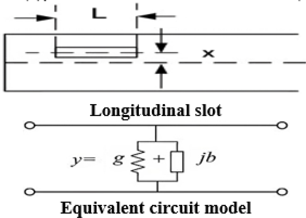
Figure 1: Slot circuit representations [15].
2 WAVEGUIDE SLOT ANTENNA DESIGN
Shunt elements in transmission lines are commonly used to represent slots. Figure 1 shows the circuit for the slot. G stands for the slot’s conductance, and B stands for the slot’s susceptance. The waveguide structure’s longitude direction is employed to cut the slot used in this study. L and W are the length and breadth of each slot, respectively. As shown in Fig. 2, d is the distance between two centered slots, and x is the offset from the center line. The d between the slots is calculated to be half the guided wavelength. As a result, the radiating slots would have a 180-degree phase shift [16, 17]. The normalized conductance Gn equations, as shown in Equation (1), are used to calculate the offset x. (1, 2).
| (1) |
| (2) |
Variables a and b are the inner dimensions of the waveguide (as depicted in Fig. 3), and the free space wavelength is represented by 0 and the guided wavelength is g, while the number of slots is represented by N. The slotted waveguide antenna’s physical dimensions, as well as its gain and beamwidth, are determined using the formulae below [17]:
| (3) |
| (4) |
| (5) |
| (6) |
| (7) |
| (8) |
Slot width and length are denoted by W and L, respectively, while the distance between slots is represented by d. Equation (3) shows how to derive the slot parameters from the operating frequency and wavelength of the guided center. Furthermore, two critical parameters, the number of slots and wavelength influence the gain and beam width. These values are also affected by the distance between slots (d). The gain is increased when the number of slots (N) increases [17]. However, as the guided wavelength (g) is raised, the distance between slots and the waveguide size is also increased [17]. As a result, the chosen slots are utilized on wave-guide walls to retain an optimal gain and a reasonable size. The structure of the waveguide is typically broadcast in TE10 mode, with both the H and E field positioned within the waveguide’s broad and narrow walls, as shown in Fig. 2. An incision will be created over H-field lines at maximum flow to enable the slot radiation [17]. This will result in one beam being generated at one of the walls. The slots on each wall side of the waveguide are carved to enable numerous beams (two or more). If the slot cutting is done on the waveguide’s narrow and broad walls, for example, a dual beam will be formed in the direction of the cutting slots. Figure 3 depicted the distribution of slots concerning the dimensions of the waveguide structure.
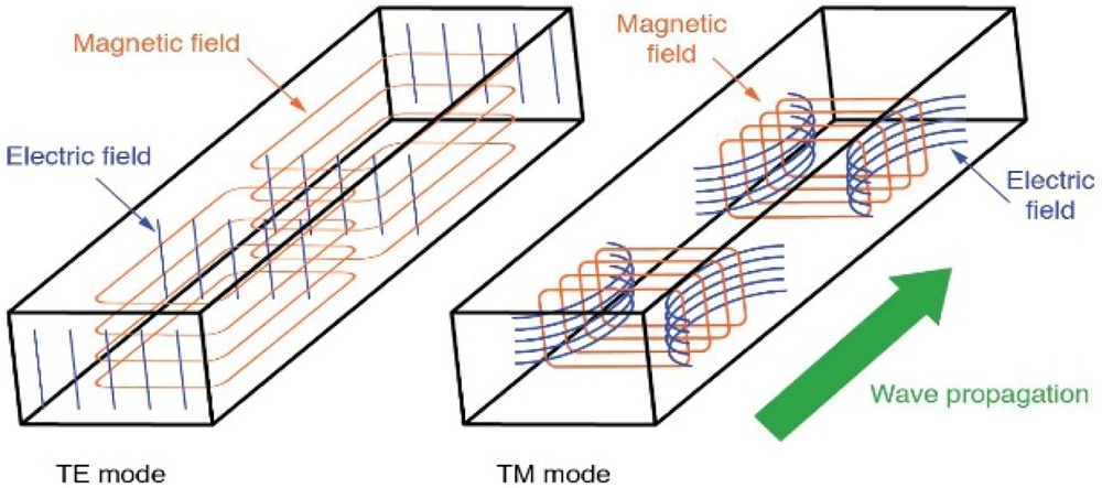
Figure 2: H and E fields distributed lines in the rectangular hollow waveguide [17].

Figure 3: The standard structure of the waveguide slots antenna [11].
Two rectangular waveguides WR34 antennas are selected to distribute slots. As shown in Fig. 4, the slot is spread on a broad and narrow wall with a tilt angle () that is spun around the slot’s center. The slots are cut symmetrically into the broad and narrow walls of the waveguide by the transverse current when the mode is TE10. As seen in Fig. 4, the horn antenna is based on the WR34 waveguide technology standard. As a result, Table 1 summarizes the intended antenna size in lambda.
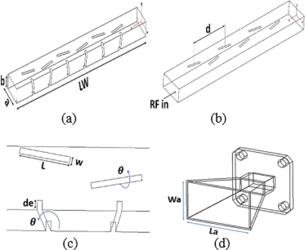
Figure 4: Proposed waveguide slots tilted antenna. (a) Broad and narrow wall slots. (b) Broad wall slots. (c) Depth and angle. (d) Horn antenna.
Table 1: A dimensions of the proposed antenna
| Parameters | Describe | Value |
|---|---|---|
| a | Broad wall | 0.75 |
| b | Narrow wall | 0.35 |
| LW | Length of waveguide | 5.2 |
| L | Length of slot | 0.46 |
| d | distance between slots | 0.63 |
| W | Width of slot | 0.052 |
| La | Length of aperture | 2.17 |
| Wa | Width of aperture | 1.52 |
| de | depth | 0.086 |
| Angle of slots | 10 degree |
3 DISCUSSION BASED ON PARAMETRIC STUDY
The performance of the reflection coefficient was investigated using the CST program. The design of this proposed antenna used waveguide standard technology which is WR34. The reflection coefficient of the proposed design depended on an angle() and depth of slots, Fig. 5 depicted the responses of the reflection coefficient, it can be determined when the angle () is changing from 0 to 15, the bandwidth increases and the frequency is adjusted at 26 GHz at the optimum slot angle of 10. The bandwidth stays the same when the slot depth of the narrow wall alterations from 0 to 1 mm, however, the frequency is increasing and the frequency is shifted as in Fig. 6.
Based on these findings, the ideal scenario for achieving satisfactory outcomes is to employ a slot angle and depth of 10 and 1 mm, respectively.
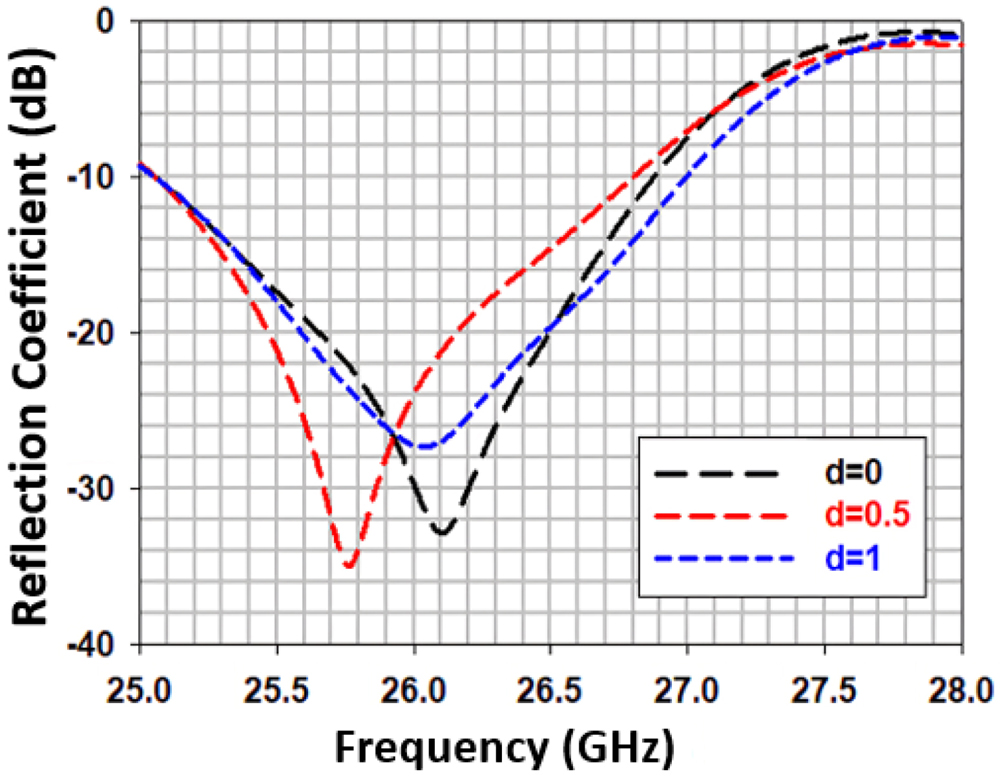
Figure 5: Titled slot versus reflection coefficient.

Figure 6: Slot depth versus reflection coefficient ( =10 degrees).
In the fabrication process, the designed antenna is metal-produced using 3D printer material. The ALSi9 material has a high casting ability, is tailored for high electrical conductivity, and has outstanding weather resistance. Figure 7 shows a prototype 3D printed off two waveguide antennas, one with title slots on both the broad and narrow walls, and the other with title slots exclusively on the broad wall, in addition to a horn antenna that was also designed using a 3D printer. Using the R&S®ZNB40 VNA, the performance of the suggested antennas is measured in terms of S-parameters (dB) and radiation pattern. A horn antenna was utilized as a reference in the radiation patterns measurement setup, which was placed in both the E-plane and H-plane directions of the tested antenna.
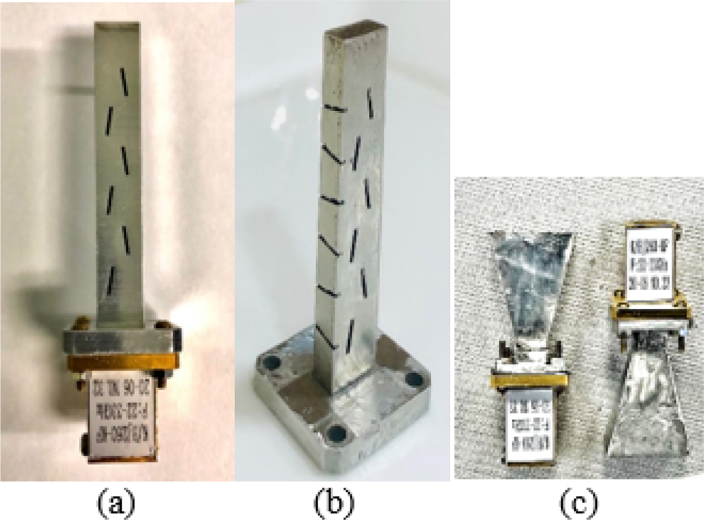
Figure 7: Fabrication of proposed design. (a) Broad wall slots. (b) Broad and narrow wall slots. (c) Horn antenna.
4 SIMULATION AND TESTING
Figure 8 shows the comparison results of the reflection coefficient between the simulation and measurement of two waveguide antennas, the measured reflection coefficient of the waveguide antenna with tilt slot on broad is shifted to a higher frequency which is 28.4 GHz while the measured reflection coefficient of waveguide antenna with tilt slot on the broad and narrow wall has Hugh bandwidth started from 22 GHz to 30 GHz which coverage the certain frequency 26 GHz. As can be seen in Fig. 9, the measured reflection coefficient of the waveguide horn antenna is still less than -10 dB with a wider bandwidth.

Figure 8: Comparison reflection coefficient of two waveguide antennae.
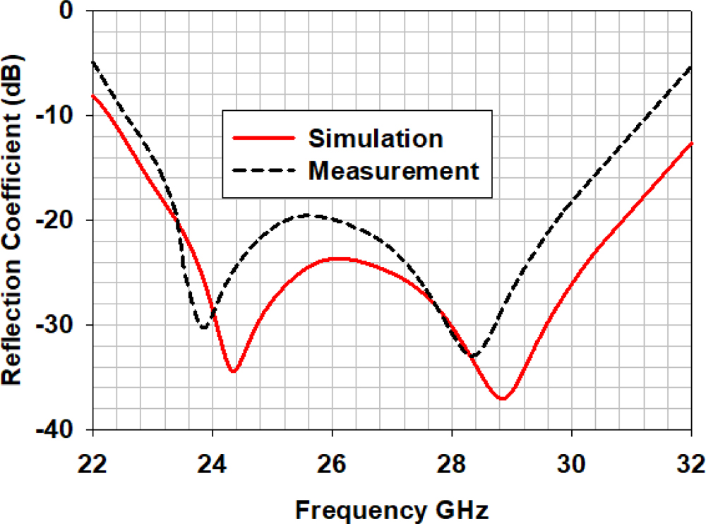
Figure 9: Comparison reflection coefficient of waveguide horn.
The front-end module’s efficiency and gain performance are then shown in Fig. 10. When the line is a curve-fitting result, the measured gains of the front-end module have frequency dependencies ranging from -180 to 180 degrees. Waveguide antennas achieved higher gains of more than 13 dB for each antenna, and the idealization of efficiency for each antenna achieved higher efficiency of 99 percent at 26 GHz, according to the fitting curve.
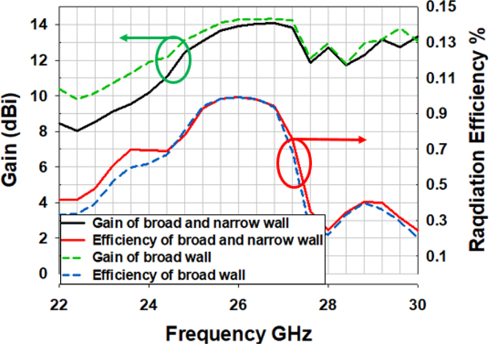
Figure 10: Gain and efficiency performance.
Figure 11 depicts the designed antenna’s radiation pattern in both implemented walls. The comparison of directivity between measurement and simulation at 26GHz in a broad wall at 0 also explains the directivity of a narrow wall as measurement and simulation of design at 26 GHz, this enables the beam to radiate at a 90 angle. The slide lobes levels concerning the back lobe levels are less than -5dB, designed with a broad and narrow wall tilt slot that has dual-beam perpendicular to each other with phase spacing between two beams of 90. Figure 12 (a) shows the 2D radiation pattern of the antenna with a broad tilt slot only as measurement and simulation radiate at 26 GHz at a 0 angle. Figure 12 (b) shows the 2D radiation pattern of the horn as measurement and simulation has a very directive beam at 26 GHz at a 0 angle. Figure 13 refers to the measurement antenna in the champter room.
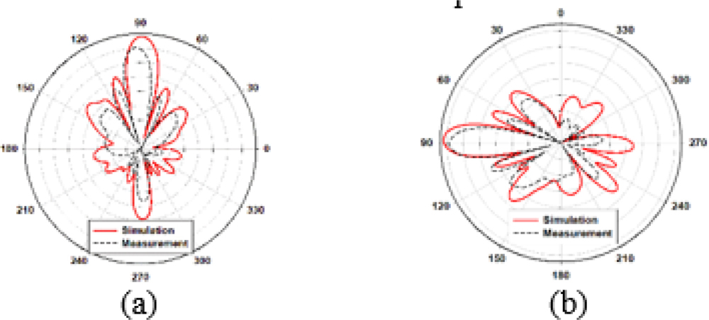
Figure 11: 2D radiation pattern of an antenna with broad and narrow wall tilt slot, (a) broad wall, (b) narrow wall.
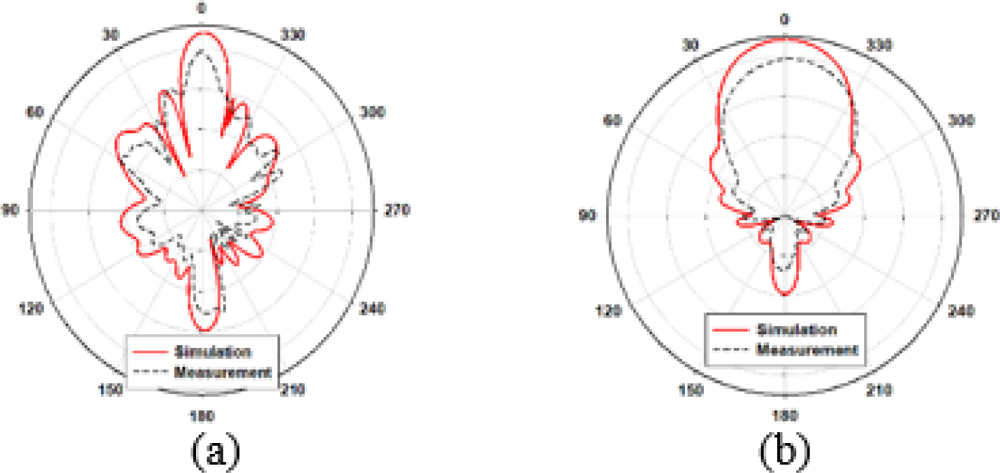
Figure 12: Depicts the 2D radiation pattern of the antenna concerning the broad wall tilt slot and horn. (a) Broad wall only and horn. (b) Horn.
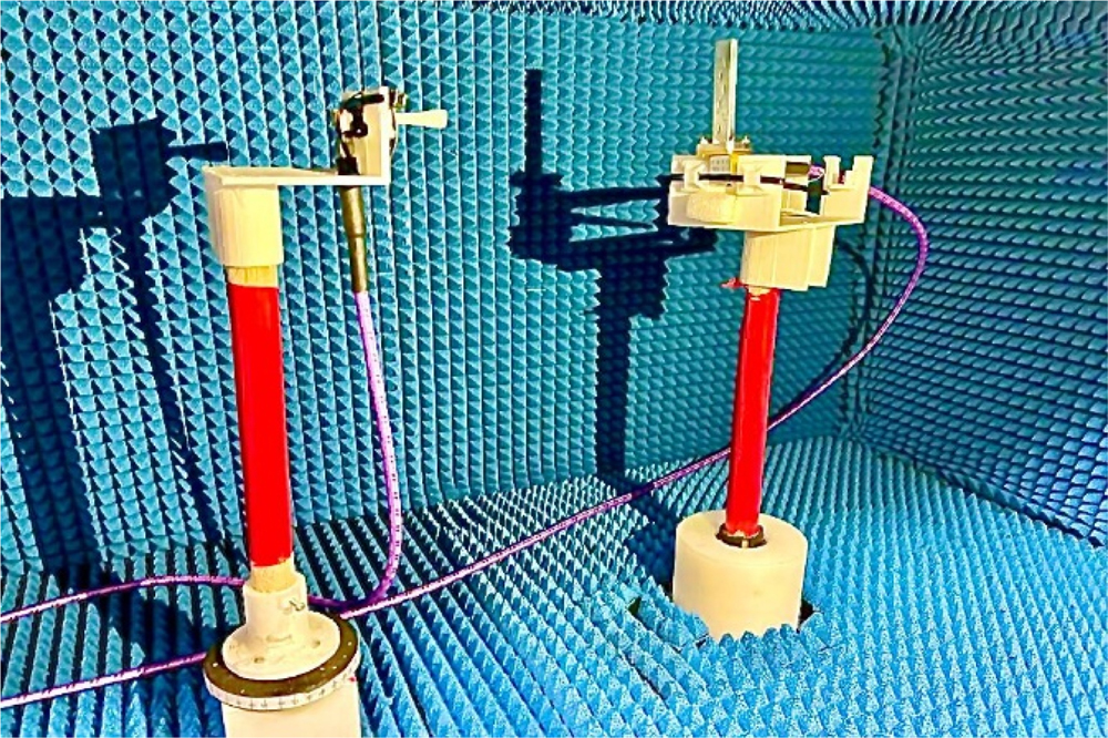
Figure 13: Measurement antenna in champter room.

Figure 14: 3D radiation. (a) Broad and narrow tilt slots. (b) Broad tilt slots. (c) Horn.
Normally, the antenna’s 3D radiation pattern is formed by the edges of the patch, but in the case of waveguides, the majority of the radiation pattern is formed by the slots of the main structure, as shown in the simulated 3D radiation pattern in Fig. 14 below. The 3D radiation pattern of the design with broad and narrow wall tilt slots and an antenna with only broad tilt slots in addition to the horn structure.
Figure 15 illustrates the surface current of three designs, it shows clearly the radiation of waveguide antenna with broad and narrow comes from tilt slots on a broad and narrow wall, in addition, the radiation of the second design which is a waveguide with board tilt slots only come from slots, slots consider as a source for radiation. The third design which is horn radiation comes from its aperture. Table 2 shows a comparison of the proposed design with existing work on dual-frequency band millimeter-wave antennas.
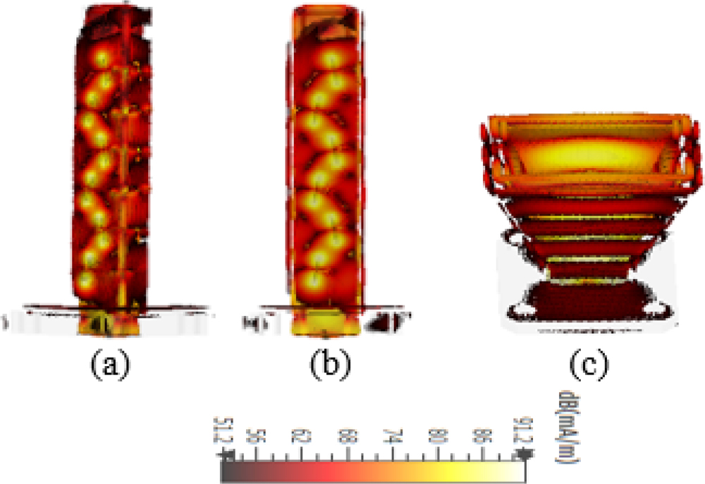
Figure 15: Surface current, (a) broad and narrow tilt slots, (b) broad tilt slots, (c) horn.
Table 2: Proposed design versus previous works
| No. Ref | Freq | No. Beam | BW | Gain | No. Slot |
| 19 | 30 | 2 | 1.5 | 13.3 | 8 |
| 20 | 28 | 2 | 0.75 | 14.4 | 8 |
| This work | 26 | 2 | 1.9 | 13.9 | 6 |
5 CONCLUSION
This paper presents a wideband and high gain waveguide slotted tilt antenna at 26 GHz. Both narrow and broad walls are tilted by 10 and the depth used with the narrow wall is 1 mm. This constructed model increases the bandwidths’ impedance. The length of each structure has six symmetric tilt slots. The reflection coefficient of the waveguide with tilt slots on the broad wall resonates as simulation at 26 GHz of -28 dB and as measurement shifted to 28.3 GHz of -15 dB. The reflection coefficient of the waveguide with tilt slots on broad and narrow walls resonates as simulation at 26 GHz of -38 dB and measurement at 26 GHz of -18 dB and produces dual beams. A waveguide with tilt slots on a broad wall achieved a gain of 14.3 dB and a bandwidth of 1.9 GHz an additional efficiency of 99% while a waveguide with tilt slots on broad and narrow walls achieved a gain of 13.9 dB and a bandwidth of 1.9 GHz with an efficiency of 99%. The proposed antenna is a decent candidate for use with millimeter waves in 5G applications. In the future, we will change the slot to a zigzag slot to increase the gain.
ACKNOWLEDGMENT
The authors would like to thank the Ministry of Higher Education (MOHE), School of Postgraduate Studies (SPS), Research Management Centre, Advanced RF, and Microwave Research Group, School of Electrical Engineering and Universiti Teknologi Malaysia (UTM), Johor Bahru, for the support of the research under Grant 09G19 and FRGS/1/2021/TKO/UTM/01/7 .
REFERENCES
[1] A. Tajik, A. S. Alavijeh, and M. Fakharzadeh, “Asymmetrical 4 4 Butler matrix and its application for single layer 8 8 Butler matrix,” IEEE Transactions on Antennas and Propagation, vol. 67, no. 8, pp. 5372-5379, 2019.
[2] H. Ren, H. Zhang, P. Li, Y. Gu, and B. Arigong, “A novel planar Nolen matrix phased array for MIMO applications,” IEEE International Symposium on Phased Array System & Technology (PAST), Waltham, MA, USA, 2019.
[3] P. Chen, W. Hong, Z. Kuai, and J. Xu, “A double layer substrate integrated waveguide blass matrix for beamforming applications,” IEEE Microwave and Wireless Components Letters, vol. 19, no. 6, pp. 374-376, 2009.
[4] R.-S. Chen, G.-L. Huang, S.-W. Wong, M. K. T. Al-Nuaimi, K.-W. Tam, and W.-W. Choi, “Bandwidth-enhanced circularly-polarized slot antenna and array under two pairs of degenerate modes in a single resonant cavity,” IEEE Antennas and Wireless Propagation Letters, 2022. doi: https://doi.org/10.1109/LAWP.2022.3209494.
[5] H. Park, G. Namgung, C. Lee, J. Kwon, and S. Kahng, “A small real-estate platform for 5G beamforming/beam-steering antennas shared with WBAN UHF-band MIMO antennas,” International Symposium on Antennas and Propagation (ISAP), Busan, Korea (South), pp. 1-2,2018.
[6] Y. M. Hussein, M. K. A. Rahim, and N. A. Murad, “Substrate integrate waveguide and microstrip antennas at 28 GHz,” Bulletin of Electrical Engineering and Informatics, vol. 9, no. 6, pp. 2462-2468, 2020.
[7] X. Xia, Q. Wu, H. Wang, C. Yu, and W. Hong, “Wideband millimeter-wave microstrip reflectarray using dual-resonance unit cells,” IEEE Antennas and Wireless Propagation Letters, vol. 16, pp. 4-7, 2017.
[8] Y. M. Hussein, M. K. A. Rahim, N. A. Murad, H. O. Hanoosh, and N. B. M. Nadzir, “Substrate integrated waveguide antenna at millimeter wave for 5G application,” Applied Computational Electromagnetics Society (ACES) Journal, vol. 37, no. 04, pp. 478-484, 2022.
[9] G. Sun and H. Wong, “A planar millimeter-wave antenna array with a pillbox-distributed network,” IEEE Transactions on Antennas and Propagation, vol. 68, no. 5, pp. 3664-3672, 2020.
[10] D. J. Bisharat, S. Liao, and Q. Xue, “High gain and low cost differentially fed circularly polarized planar aperture antenna for broadband millimeter-wave applications,” IEEE Transactions on Antennas and Propagation, vol. 64, no. 1, pp. 33-42, 2016.
[11] H. O. Hanoosh, M. K. A. Rahim, N. A. Murad, and Y. M. Hussein, “Multi-beams waveguide slot antennas at X-band for wireless communications systems,” Applied Computational Electromagnetics Society (ACES) Journal, vol. 35, no. 7, pp. 797-802, 2020.
[12] R. V. Gatti and R. Rossi, “A dual-polarization slotted waveguide array antenna with polarization-tracking capability and reduced sidelobe level,” IEEE Transactions on Antennas and Propagation, vol. 64, no. 4, pp. 1567-1572, 2016.
[13] Y. F. Wu and Y. J. Cheng, “Conical conformal shaped-beam substrate-integrated waveguide slot array antenna with conical-to-cylindrical transition,” IEEE Transactions on Antennas and Propagation, vol. 65, no. 8, pp. 4048-4056, 2017.
[14] H. O. Hanoosh, M. K. A. Rahim, N. A. Murad, and Y. M. Hussein, “High gain waveguide tilted slot antenna for millimeter wave application,” IEEE International Symposium on Antennas and Propagation and USNC-URSI Radio Science Meeting (APS/URSI), pp. 125-126, 2021. doi: https://doi.org/10.1109/APS/URSI47566.2021.9703881.
[15] D. S. Ramkiran, B. T. P. Madhav, K. Narasimha Reddy, S. Shabbeer, Pr. Jain, and S. Sowmya, “Coplanar wave guide fed dual band notched MIMO antenna,” International Journal of Electrical and Computer Engineering (IJECE), vol. 6, no. 4, p. 1732-1741, 2016.
[16] R.-S. Chen, X.-D. Li, H.-L. Liu, G.-L. Huang,S.-W. Wong, M. K. T. Al-Nuaimi, K.-W. Tam, and W.-W. Choi, “Reconfigurable full-metal circularly-polarized cavity-backed slot antenna and array with frequency and polarization agility,” IEEE Transactions on Circuits and Systems II: Express Briefs, vol. 70, no. 2, pp. 531-535, Feb. 2023.
[17] R. S. Elliott, Antenna Theory and Design, Revised Edition, John Wiley & Sons, New York, USA, pp. 305-315, 2017.
[18] Muataz W. Sabri, Noor A. Murad, and M. K. Rahim, “Bi-directional beams waveguide slotted antenna at millimeter wave,” TELKOMNIKA, vol. 16, no. 4, pp. 1515-1521, Aug. 2018.
[19] M. W. Sabri, N. A. Murad, M. K. A. Rahim, “Highly directive 3D-printed dual-beam waveguide slotted antennas for millimeter-wave applications,” Microw Opt Technol Lett., © 2019 Wiley Periodicals, Inc., pp. 1-8, 2019.
BIOGRAPHIES

Hatem O. Hanoosh was born in Samawah, Iraq, in 1991. He received the B.S. degree in computer techniques engineering in 2014-2015 from Islamic University College, Najaf City. He received the M.S. degree in electronic engineering (telecommunication system) from University Technical Malaysia Melaka (UTEM), Malaysia, in 2018, respectively, and he is currently working toward the Ph.D. degree in electronic engineering with University Technology Malaysia (UTM), Johor Bahru City. His current research interests include millimeter-wave antennas, base station antennas, waveguide slot antennas and Nolen matrix.

M. K. A. Rahim received the B.Eng. degree in electrical & electronics from the University of Strathclyde, U.K., in 1987. He received the M.Eng. degree in science from the University of New South Wales, Australia, in 1992 and the Ph.D. degree in electrical engineering from University of Birmingham, U.K., in 2003.He is a Professor in RF & Microwave and Antenna at School of Electrical Engineering, Universiti Teknologi Malaysia. His research interest includes the areas of radio frequency, microwave and antennas. He has been awarded with top research publication in 2015, 2017, and 2020. In 2018, he was honored as “Tokoh Penyelidik” at CITRA KARISMA UTM, and in the same year, he was awarded with Top Research Scientist Malaysia (TRSM) award by Academy Science of Malaysia.

N. A. Murad received her first degree, Bachelor of Engineering (Electrical – Telecommunications), in 2001 from Universiti Teknologi Malaysia (UTM). Shortly after graduation, she served UTM as a tutor. She graduated with Master of Engineering (Electrical) in 2003 from the same university and has been appointed as a Lecturer in April 2003. She joined Emerging Device Technology Group, University of Birmingham, U.K., and obtained the Ph.D. degree in 2011 for research on micromachined millimeterwave circuits. She attached to HID GLOBAL Sdn Bhd for one year under Research and Development specifically working on RFID tag design, testing, and development. Her research interests include antenna design for RF and microwave communication systems, millimeter-wave circuits design, RFID, and antenna beamforming. Currently, she is a senior member of IEEE (MIEEE), MBOT Professional Technologist, and an Associate Professor with the School of Electrical Engineering, Universiti Teknologi Malaysia (UTM).

Yaqdhan M. Hussein was born in Samawah, Iraq, in 1991. He received the B.S. degree in computer techniques engineering in 2014-2015 from Islamic University College, Najaf city, and the M.S. degree in electronic engineering (telecommunication system) from Universiti Teknikal Malaysia Melaka (UTeM), Malaysia, in 2018, respectively, and he is currently working toward the Ph.D. degree in electronic engineering with Universiti Teknologi Malaysia (UTM), Johor Bahru city. His current research interests include millimeter-wave antennas, base station antennas, and SIW technology with butler matrix.
ACES JOURNAL, Vol. 37, No. 11, 1162–1169
doi: 10.13052/2022.ACES.J.371107
© 2022 River Publishers