Phase-shifter-less Vortex Electromagnetic Wave Generation Technology with Tunable Topological Charge/Steering Angle under Random Initial Phase Condition of Phase-locked Source
Yuliang Zhou, Kaiyuan Yao, Xiaona Li, Yong Mao Huang, and Haiyan Jin
1School of Aeronautics and Astronautics
University of Electronic Science and Technology of China, Chengdu, 611731, China
uestcjhy@uestc.edu.cn
2School of Electrical and Electronic Information
Xihua University, Chengdu, 610097, China
Submitted On: August 13, 2022; Accepted On: February 20, 2023
ABSTRACT
This paper demonstrates how to implement a vortex electromagnetic wave generation system with beam steering using only delay lines as phase-shifting elements. The system is based on uniform circular array and phased array technology. A detailed theoretical derivation is presented, which yields an input frequency matrix corresponding to each target case. Furthermore, considering the random initial phase problem of the actual phase-locked source, the above scheme is further improved in this paper. By cleverly setting the circuit structure, the influence of the initial phase inconsistency on the phase control system is filtered out. The performance is verified by analytical calculations and full-wave electromagnetic simulations, which are in good agreement with the proposed theory. The scheme proposed in this paper can completely get rid of the phase shifter and realize the free adjustment of the topological charge number/beam steering angle. The adjustment accuracy depends on the tuning accuracy of the phase-locked source, which can achieved an accuracy over 1Hz at a cost of less than six dollars, which makes it an interesting and flexible low-cost vortex electromagnetic wave generation scheme.
Index Terms: OAM (orbital angular momentum) wave, phase-shifter-less, random initial phase, tunable steering angle, tunable topological charge.
I. INTRODUCTION
Over the past decades, investigations have shown that electromagnetic waves not only have spin angular momentum, but also orbital angular momentum [1]. Some subsequent studies have stated clearly that electromagnetic waves carrying orbital angular momentum, called vortex electromagnetic waves, have a helical phase structure, whose wavefront rotates along the beam axis in space [2]. The vortex electromagnetic waves of different OAM modes have different phase structures, and the integer modes are orthogonal to each other [3], which means that the orbital angular momentum can provide rotational degrees of freedom for the electromagnetic field and this is beneficial for novel multiplexing applications [4, 5]. Orbital angular momentum has been discovered in optical research [1], and vortex electromagnetic waves have been used in radar imaging [6], quantum state manipulation [7], identification of scatterer characteristics [8], 2D underwater imaging [9] and other fields.
The state-of-the-art OAM generation architectures can be mainly divided into four types, namely transmission helical structure [10], transmission grating structure [11], helical reflector structure [12] and array antenna [13, 14]. When vortex electromagnetic waves were first proposed, the proponents described how to feed a uniform circular array to generate orbital angular momentum in the radio frequency band [15]. A uniform circular phased array has the advantages of simple processing and easy operation, so it is a good vortex electromagnetic wave generator [16]. As one of the commonly used methods of generating vortex electromagnetic waves [17, 18], the uniform circular array antenna usually needs to be used with phase shifters [19, 20, 21]. Due to the high cost of phase shifters, many authors try to replace the phase shifter with other structures in the design of the OAM generator [22, 23, 24]. However, none of these solutions have good reconfigurability.
In this work, an effective OAM phased array implementation method based on the uniform circular array antenna is proposed to achieve system reconfigurability at low cost. In some schemes, delay lines are used instead of phase shifters to generate vortex electromagnetic waves with different topological charges, which simplifies the system. However, if the beam pointing control of OAM is to be further realized without changing the length of the delay line, the phase shifter is still required. In contrast, the proposed technique can be performed without other phase-shifting units. By adjusting the frequency of each local oscillator signal, a vortex electromagnetic wave generation system with arbitrary topology charge and beam pointing angle is designed without the need for phase shifters.
II. LOW-COST OAM PHASED ARRAY SYSTEM
A. Low-cost OAM phased array circuit-level implementation technology
The uniform circular array used to generate vortex electromagnetic waves is shown in Fig. 1 (a).
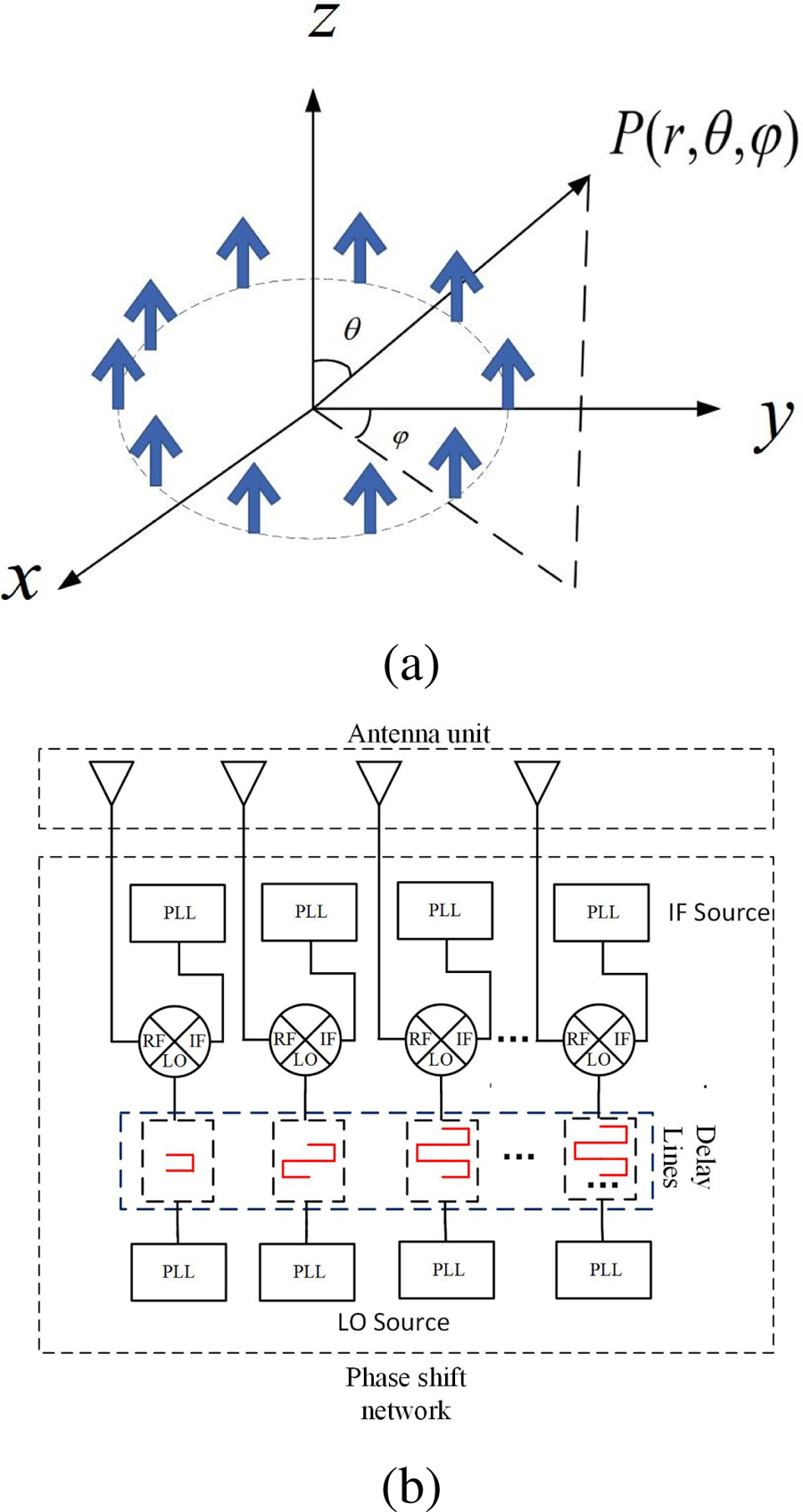
Figure 1: (a) Diagram of the circular array configuration, and (b) low-cost OAM phased array system schematic diagram.
The far-field radiation pattern for a uniform circular array is [25]:
| (1) |
where , is the amplitude of the excitation signal for each antenna element, and is the phase relationship of them. When (), the directional pattern function of the array is [7]:
| (2) |
It carries a phase factor , so it can generate vortex electromagnetic waves, where is the mode of OAM. On this basis, the beam pointing control factor is added. If the preset pointing angle is , the phase excitation vector of each array element can be given by the following equation [26]:
| (3) |
Therefore, to generate a vortex electromagnetic wave with a topological charge of , and a beam pointing angle of , the phase shift should be [15]:
| (4) |
By plugging Eq. 4, the radiation pattern is re-obtained as [27]:
| (5) |
where , , , . It can be seen that after adding beam pointing control, the array factor function still carries the azimuth component, which proves that it also has the characteristics of vortex electromagnetic waves.
The system schematic diagram is shown in Fig. 1 (b). Beam steering is performed by simply changing the radiation frequency, since the necessary phase shifts are provided by the delay lines [28]. The phase-modulated signal is sent by M channels of local oscillator signal sources, and the phase is adjusted through the fixed-length delay line. After that, the signals are mixed with the M channels of intermediate frequency signal sources through the heterodyne mixer, which form the TX chains and then send the mixed signal into the antenna array through a filter. In this way, the purpose of adjusting the phase of each antenna unit without changing its finally radio frequency is achieved.
Let the IF signal be , and the local oscillator signal be . After mixing the two and filtering:
| (6) |
When the frequency of the local oscillator signal increases , the frequency of the intermediate frequency signal decreases . Let the delay line act on the local oscillator signal source, the local oscillator signal will add a phase shift generated by passing through them, and at this time the local oscillator signal is:
| (7) |
If the phase shift constant of the delay line is , let the length of the delay line be , and the corresponding phase shift is . By plugging it into Eq. 7, and assuming that the initial phase of the signal source is 0, we obtain:
| (8) |
In order to obtain the vortex electromagnetic wave, the phase offset required for the mth array element is . Then, the length of the delay line corresponding to the mth array element is calculated as:
| (9) |
where is the input frequency of the delay line corresponding to the mth element. Set , , and substitute into Eq. 9 to obtain:
| (10) |
To determine the length of the delay line corresponding to each array element by Eq. 10, let it be , and set . By plugging Eq. 10 into Eq. 9 it, we obtain: , and then we can obtain the frequency matrix as:
| (11) |
This is a matrix with rows and columns, (the rows and columns correspond to the topological charge and the array element serial number respectively), and its value is the frequency value that the local oscillator signal source needs to output.
It can be seen that if the delay line-based system is used to generate vortex electromagnetic waves, when the length of the delay line is determined and control beam pointing is not considered, there is a linear relationship between the frequency and the topological charge. The frequency of the input signal required by the time line is the same. Therefore, only two signal sources are required to output eight local oscillator signals and eight intermediate frequency signals, respectively, through the power divider.
If the beam is deflected with an angle of , the phase offset required by the mth array element is given by Eq. 4. At this time, the output frequency of the local oscillator signal source corresponding to the mth array element is:
| (12) |
Let the length of the delay line still be , to make the beam pointing angle =, let =, and set: . Then Eq. 12 can be written as: . Finally, the frequency matrix is written as:
| (13) |
Eq. 13 is the frequency matrix corresponding to the local oscillator signal. It can be seen from Eq. 13 that after adding beam pointing control, the input frequencies required for the corresponding delay lines of different array elements under the same topology load and beam pointing angle are no longer the same, so one signal source cannot be used to provide all entries.
If the final RF signal frequency is , the frequency matrix corresponding to the intermediate frequency signal is .
To sum up, without changing the length of the delay line, the system needs 2 M signal sources, including M local oscillator signal sources and M intermediate frequency signal sources. In practical applications, two groups of one-way constant temperature crystal oscillators plus M-way phase-locked loops can be used to realize this function.
B. Electromagnetic simulation
Select a uniform circular antenna array with eight elements, select the X-band (10GHz) as the RF frequency, and simulate the system in Systemvue. When the beam pointing angle is (0, 0) and the OAM mode is 1, select 500MHz as the M-channel local oscillator signal source output frequency. On this basis, according to Eq. 13, the frequency value of the output signal of each signal source is regulated to generate different forms of vortex electromagnetic waves. The system block diagram is shown in Fig. 2.

Figure 2: System block diagram.
In this paper’s simulation, the beam pointing angle is uniformly specified in the direction of the lowest amplitude value in the zero-depth region. As shown in Fig. 3, when the topological charge is both 1 and the pointing angle is (15, 15) and (30, 30) respectively, (a) and (b) reveal the relationship curves between the amplitude value and the pitch angle on the azimuth pointing plane. The angle corresponding to the minimum amplitude value is the beam deflection angle. Panels (c) and (d) in Fig. 3 indicate the situation when the pointing angles are same but the topological charge generated is changed to 2. Therefore we can conclude that when the 30dB deviation is used as the standard, under the same topological charge condition, the angle occupied by the zero-depth area is proportional to the beam deflection angle value. When the influence of the deflection angle is not considered, the zero-depth area will follow the OAM mode and increased significantly. In the lower right corner of each picture in Fig. 3, there is a complete array pattern. It can be seen that the system has achieved splendid results in the control of azimuth and pitch angles, and can maintain the structure of vortex electromagnetic waves at thesame time.
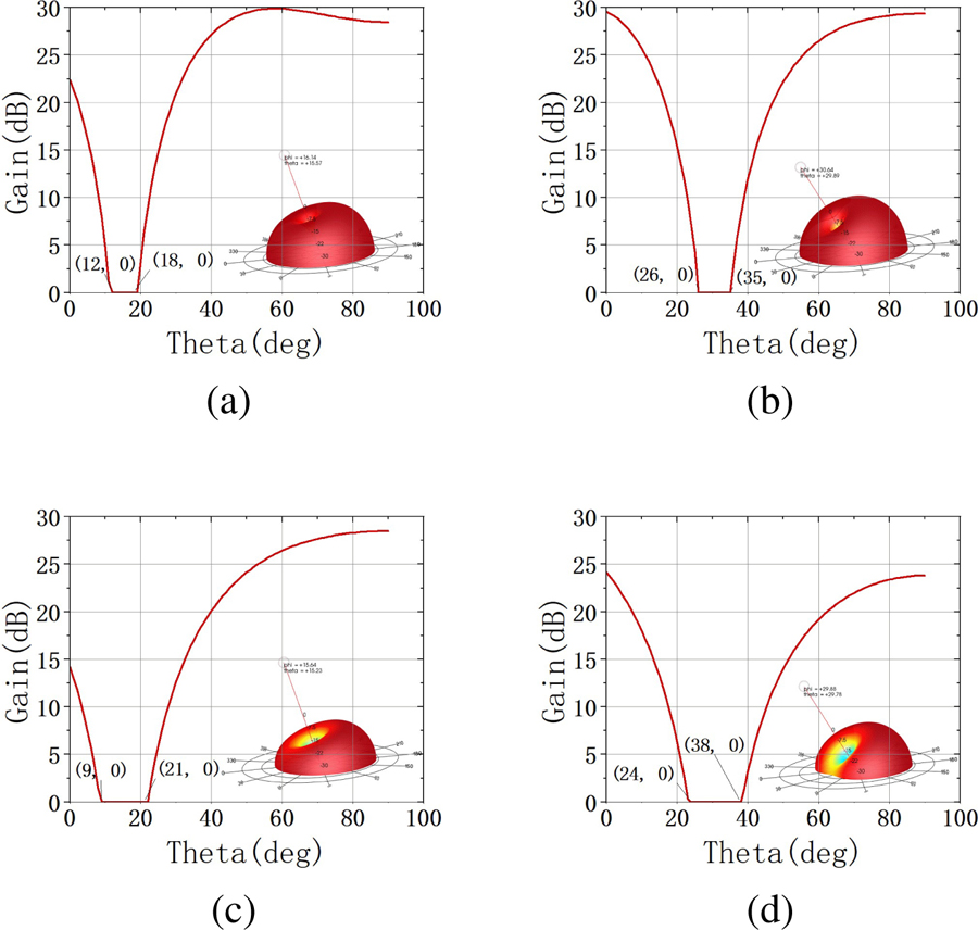
Figure 3: Array pattern. (a) Charge1 (15,15). (b) Charge1 (30,30). (c) Charge2 (15,15). (d) Charge2 (30,30).

Figure 4: After adding random initial phase: (a) Pattern, and (b) Phase diagram.
Multiple phase-locked loops in a system can maintain the same initial phase when outputting the same frequency signal, but different phase-locked loops in this paper need to output different frequencies, so the initial phase of each signal becomes random. This will cause the phase relationship between the signals that are finally fed to the antenna elements of the array to no longer be as preset, and the impact will be devastating. A random initial phase of 0-360 is assigned to a certain number of signal sources in Fig. 2. Set the topological load is a 1, and the pitch angle deflection is 20, the generated pattern and phase diagram are shown in Figs. 4 (a) and (b), respectively.
It can be seen that the phased structure of the vortex electromagnetic wave was damaged, and if the system is executed a second time, another unordered result will be randomly obtained, so it needs to be improved.
III. RANDOM INITIAL PHASE CONDITIONS SYSTEM
A. Improved scheme of phase-locked source under random initial phase conditions
According to Section II A, the premise that the system can successfully achieve the expected effect requires that the initial phases of the M channels of local oscillator signal sources are consistent, and the same is true of the M channels of IF signal sources. If there is an initial phase difference between the signal sources, the difference will remain until the final signal input to the antenna array, which will eventually destroy the phase control structure of the vortex electromagnetic wave generation system, as in Fig. 4. However, because of the system’s constant temperature crystal oscillator and M-channel phase-locked loop, it cannot guarantee that the initial phase is still consistent after random frequency modulation. In contrast to the instantaneous phase, the initial phase has no practical significance and an accurate and effective measurement method, so it is difficult to realize in practice.
According to equation, when the topological charge is , and the control beam angle is , the required output frequency of each local oscillator signal is , and each IF signal is . If the frequency of one LO signal source is preset as , and the frequency of one IF signal source is set as , then each of them needs to be added or subtracted , which is the required frequency. Therefore, we can mix these two signals with M signals of frequency (here called weighted signals), and then filter out the interference frequency, and the output signal frequency is the required value.
The schematic diagram of the improved system is shown in Fig. 5, and in this way, the primary phase interference can be eliminated.
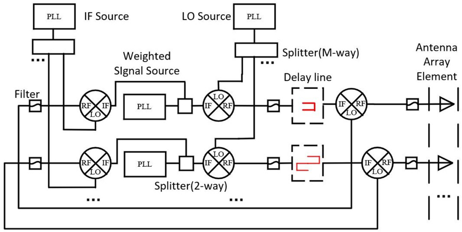
Figure 5: Random initial phase condition system schematic diagram.
Let the IF signal be , the local oscillator signal be , and the m-way weighted signal be:
| (14) |
where , , are all random phases from 0 to 360. After mixing and filtering with the m-way weighted signals, the intermediate frequency signal and the local oscillator signal become:
| (15) |
| (16) |
After that, the local oscillator signals of each channel pass through the delay line to obtain:
| (17) |
where is the desired phase difference relationship. The M channels of local oscillator signals are mixed with the intermediate frequency and filtered, and the final signal is obtained as:
| (18) |
where and are independent of the array element number m, except for , there is no additional phase difference between the signals input to each antenna unit, and the structure of vortex electromagnetic wave and beam pointing control remainsintact.
B. Electromagnetic simulation
The system block diagram in Systemvue is shown in Fig. 6. The uniform circular antenna array with eight elements and the X band radio frequency are still selected. A random initial phase of 0-360 is added to each signal source in Fig. 6.
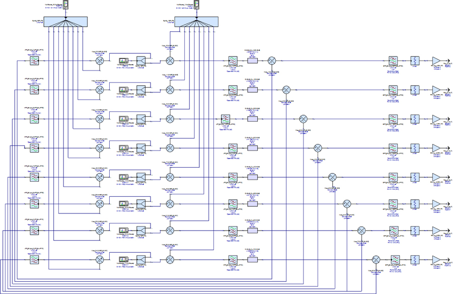
Figure 6: Random initial phase condition system block diagram.
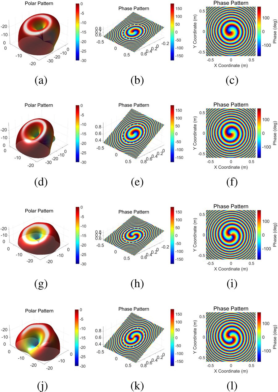
Figure 7: Charge1 (15,0). (a) Pattern. (b) Phase diagram with pointing. (c) Phase diagram Charge1 (30,0). (d) Pattern. (e) Phase diagram with pointing. (f) Phase diagram Charge2 (15,0). (h) Pattern. (h) Phase diagram with pointing. (i) Phase diagram Charge2 (30,0). (j) Pattern. (k) Phase diagram with pointing. (l) Phase diagram.
The system is simulated and the results obtained are shown in Fig. 7. When the topological load is set to 1 and the beam pointing is set to (15, 0), (a) is the pattern of the array, and it can be seen that the pitch angle is shifted by a certain degree. As shown in (b), the plane is intercepted with the pointing axis of (a) as the normal and the phase diagram is drawn when the condition of the circular field is satisfied. (c) is the front view of the phase map. (j) (k) (l) show the same situation when the OAM mode is 2 and the beam pointing is (30, 0). As can be seen from Fig. 7, even if the initial phases of the various signal sources are inconsistent, the system can still offset the effects and obtain ideal results. In order to further verify the system’s effect, the OAM spectrum is drawn here. It can be seen that there is a circle of white lines on the phase diagram of the three-dimensional space in Figs. 7 (b) and (d), which is the ring current selected as the reference for the OAM spectrum drawing. As shown in Fig. 8, (a) and (b) are histograms of the purity of each OAM mode with the topological charge set to 1 and the pitch angle pointing set to 15 and 30 respectively, (c) and (d) are for the same case but the topological charge is set to 2.
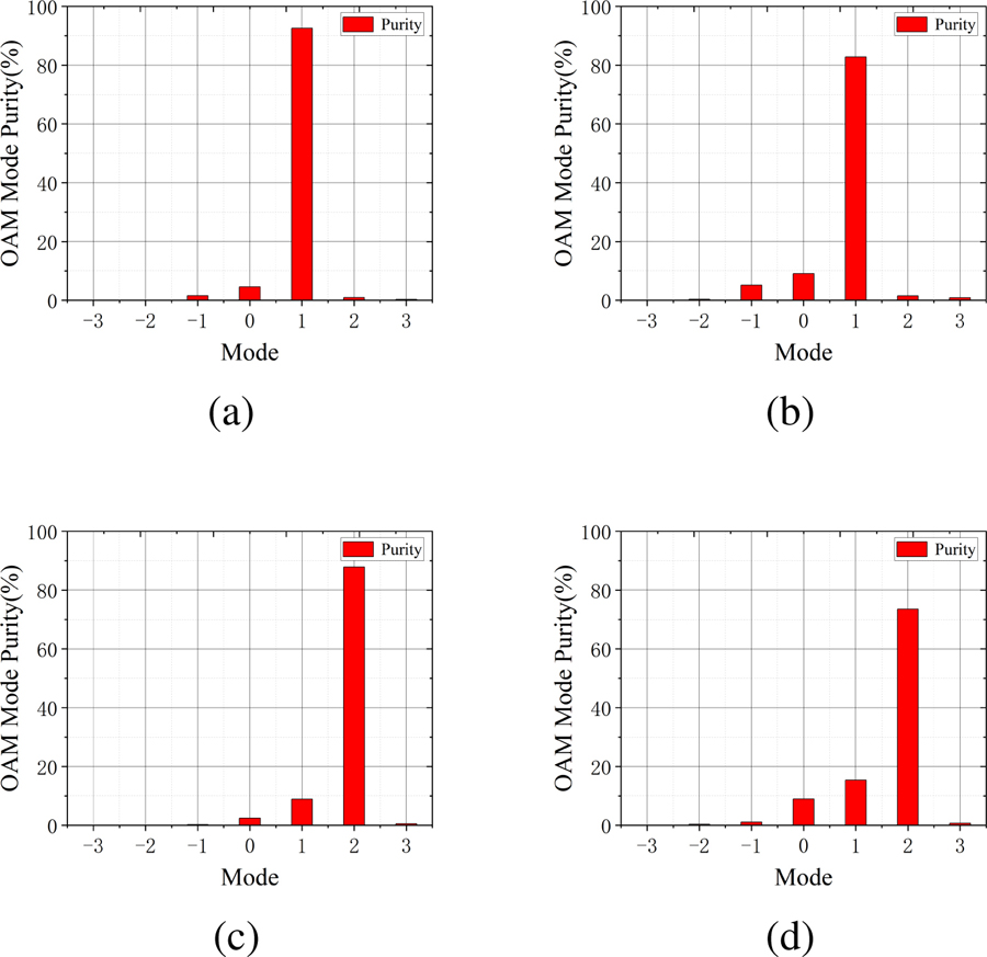
Figure 8: OAM mode purity. (a) Charge1 (15,0). (b) Charge1 (30,0). (c) Charge2 (15,0). (d) Charge2 (30,0).
It can be seen from Fig. 7 that the OAM generated by the system has good purity, and, under the same topological charge, when the angular deflection increases, the OAM purity has a relatively obvious decline. When the angular orientation control is not considered, the closer the topological charge is to , and the purity also decreases to a certain extent.
IV. CONCLUSION
In this work, a vortex electromagnetic wave generation system with beam steering function is designed based on the delay line. The system is improved by rearranging the phase-locked loop and the signal source, so that it cannot be affected by the phase noise to a certain extent. At the same time, the phase interference which cannot be handled by the initial phase random structure can be compensated by modifying the frequency matrix, Eq. 13, which increases the robustness of the system. The two systems were separately modeled in Systemvue for electromagnetic simulation and structure analyses of the generated vortex electromagnetic wave, which subsequently demonstrates that the proposed system has achieved quite good results. It can generate vortex electromagnetic waves of various modes in the range of , and control the beam pointing with high precision. Future work is expected to focus on achieving sidelobe suppression, and further optimization of the system structure.
DECLARATION OF COMPETING INTEREST
The authors declare that they have no known competing financial interests or personal relationships that could have appeared to influence the work reported in this paper.
REFERENCES
[1] L. Allen, M. W. Beijersbergen, R. Spreeuw, and J. Woerdman, “Orbital angular momentum of light and the transformation of laguerre-gaussian laser modes,” Phys. Rev. A vol. 45, no. 11, 8185, 1992. doi:10.1103/PhysRevA.45.8185.
[2] S. M. Mohammadi, L. K. Daldorff, J. E. Bergman, R. L. Karlsson, B. Thidé, K. Forozesh, T. D. Carozzi, and B. Isham, “Orbital angular momentum in radio—A system study,” IEEE Trans. Antennas and Propag., vol. 58, no. 2, pp. 565-572, 2009. doi:10.1109/TAP.2009.2037701.
[3] F. Tamburini, E. Mari, A. Sponselli, B. Thidé, A. Bianchini, and F. Romanato, “Encoding many channels on the same frequency through radio vorticity: first experimental test,” New J. Phys., vol. 14, no. 3, 033001, 2012. doi:10.1088/1367-2630/14/3/033001.
[4] B. Thidé, F. Tamburini, H. Then, C. Someda, and R. Ravanelli, “The physics of angular momentum radio,” arXiv:1410.4268, 2014. doi:10.1109/ursi-at-rasc.2015.7302908.
[5] L. Li and F. Li, “Beating the rayleigh limit: Orbital-angular-momentum-based super-resolution diffraction tomography,” Phys. Rev. E, vol. 88, no. 3, 033205, 2013. doi:10.1103/physreve.88.033205.
[6] K. Liu, Y. Cheng, Z. Yang, H. Wang, Y. Qin, and X. Li, “Orbital-angular-momentum-based electromagnetic vortex imaging,” IEEE Antennas Wirel. Propag. Lett., vol. 14, pp. 711-714, 2014. doi:10.1109/LAWP.2014.2376970.
[7] A. Vaziri, G. Weihs, and A. Zeilinger,“Superpositions of the orbital angular momentum for applications in quantum experiments,”J. Opt. B: Quantum Semiclass. Opt., vol. 4, no. 2, S47, 2002. doi:10.1088/1464-4266/4/2/367.
[8] H.-T. Chen, Z.-Q. Zhang, and J. Yu, “Near-field scattering of typical targets illuminated by vortex electromagnetic waves,” Applied Computational Electromagnetics Society Journal (ACES), pp. 129-134, 2020.
[9] Y. Yang, G. Liu, F. Shen, J. Sun, K. Guo, Z. Guo, Q. Zhou, H. Jiang, Z. Wu, B. Zeng, “Generating and detecting broad-band underwater multiple oams based on water-immersed array,” IEEE Access, vol. 8, pp. 149586-149594, 2020. doi:10.1109/ACCESS.2020.3016389.
[10] Y. Jiang, Y. He, and F. Li, “Wireless communications using millimeter-wave beams carrying orbital angular momentum,” 2009 WRI Int. Conf. Commum. Mobile Comput., vol. 1, pp. 495-500, 2009. doi:10.1109/CMC.2009.315.
[11] V. Vaishnavi, V. Priya, M. Kumar, S. Venkatesh, G. A. S. Sundaram “Simulation of helical modulation in a focal plane array,” 2014 Int. Conf. Commun. Signal Process., Melmaruvathur, India, 2014, pp. 1414-1418. doi:10.1109/ICCSP.2014.6950082.
[12] F. E. Mahmouli and S. D. Walker, “4-gbps uncompressed video transmission over a 60-ghz orbital angular momentum wireless channel,” IEEE Wirel. Commun. Lett., vol. 2, no. 2, pp. 223-226, 2013. doi:10.1109/WCL.2013.012513.120686.
[13] H.-T. Chen, R. Pan, W.-Z. Sun, and S.-Y. He, “Microstrip reflectarray for generation of electromagnetic waves with beam vorticity,” Applied Computational Electromagnetics Society Journal (ACES), vol. 33, no. 5, pp. 488-493, 2018.
[14] Q. Feng, Y. Lin, Y. Zheng, and L. Li, “Vortex beam optimization design of concentric uniform circular array antenna with improved array factor,” Applied Computational Electromagnetics Society Journal (ACES), vol. 36, no. 7, pp. 830-837, 2021.
[15] B. Thidé, H. Then, J. Sjöholm, K. Palmer, J. Bergman, T. Carozzi, Y. N. Istomin, N. Ibragimov, and R. Khamitova, “Utilization of photon orbital angular momentum in the low-frequency radio domain,” Phys. Rev. lett., vol. 99, no. 8, 087701, 2007. doi:10.1103/physrevlett.99.087701.
[16] J. D. Jackson, Classical Electrodynamics, John Wiley & Sons, New York, 1999.
[17] Q. Bai, A. Tennant, B. Allen, and M. U. Rehman, “Generation of orbital angular momentum (oam) radio beams with phased patch array,” 2013 Loughborough Antennas Propag. Conf. (LAPC), pp. 410-413, 2013.
[18] Q. Bai, A. Tennant, E. Cano, and B. Allen, “An experimental phased array for oam generation,” 2014 Loughborough Antennas Propag. Conf. (LAPC), Loughborough, 2014, pp. 165-168. doi:10.1109/LAPC.2014.6996347.
[19] K. Liu, H. Liu, Y. Qin, Y. Cheng, S. Wang, X. Li, and H. Wang, “Generation of oam beams using phased array in the microwave band,” IEEE Trans. Antennas Propag., vol. 64, no. 9, pp. 3850-3857, 2016. doi:10.1109/TAP.2016.2589960.
[20] M. Klemes, H. Boutayeb, and F. Hyjazie, “Orbital angular momentum (oam) modes for 2-d beam-steering of circular arrays,” 2016 IEEE Can. Conf. Electr. Comput. Eng. (CCECE), Vancouver, BC, Canada, pp. 1-5, 2016. doi:10.1109/CCECE.2016.7726746.
[21] T. Yuan, Y. Cheng, H. Wang, and Y. Qin, “Beam steering for electromagnetic vortex imaging using uniform circular arrays,” IEEE Antennas Wirel. Propag. Lett., vol. 16, pp. 704-707, 2016. doi:10.1109/LAWP.2016.2600404.
[22] P. Mao and C. Gao, “Design and simulation of a hexagonal microstrip array antenna with oam,” 2019 Int. Conf. Intell. Comput., Automat. Sys. (ICICAS), Chongqing, China, pp. 100-104,2019.
[23] Y. Wang, J. Liu, D. Yang, and W. Jie, “Generation of multiple oam modes using time-modulated concentric circular arrays,” 2019 Int. Symp. Antennas Propag. (ISAP), Xi’an, China, pp. 1-2, 2019.
[24] S. Tan, J. Dong, M. Wang, Z. Jiang, X. Zhuang, and L. Deng, “New circular array configurations for generating orbital angular momentum (oam) beams,” 2018 Int. Appl. Comput. Electromagn. Soc. Symp.-China (ACES), Beijing, China, pp. 1-2, 2018.
[25] D. G. Grier, “A revolution in optical manipulation,” Nature, vol. 424, no. 6950, pp. 810-816, 2003. doi:10.1038/nature01935.
[26] K. Liu, Y. Cheng, H. Wang, X. Li, and Y. Qin, “Radiation pattern synthesis for the generation of vortex electromagnetic wave,” IET Microw. Antennas Propag., vol. 11, no. 5, pp. 685-694, 2017. doi:10.1049/iet-map.2016.0681.
[27] K. Liu, Y. Cheng, X. Li, H. Wang, Y. Qin, and Y. Jiang, “Study on the theory and method of vortex-electromagnetic-wave-based radar imaging,” IET Microw. Antennas Propag., vol. 10, no. 9, pp. 961-968, 2016. doi:10.1049/iet-map.2015.0842.
[28] T. Nishio, H. Xin, Y. Wang, and T. Itoh, “A frequency-controlled active phased array,” IEEE Microw. Wirel. Compon. Lett., vol. 14, no. 3, pp. 115-117, 2004. doi:10.1109/LMWC.2004.825188.
BIOGRAPHIES

Yuliang Zhou received a B.S. degree in Applied Physics and the Ph.D. degree in Communication and Information Systems from the University of Electronic Science and Technology of China, Chengdu, China, in 2012 and 2020, respectively. Now he is a Post-Doctoral Researcher with the School of Aeronautics and Astronautics, University of Electronic Science and Technology of China.
From 2017 to 2018, he was with the Microwave Laboratory, University of Pavia, Pavia, Italy. His current research interests include substrate integrated circuits, leaky-wave antennas, and systems for wireless communication.
Kaiyuan Yao was born in Dengzhou, Henan, China in 2000 and obtained the degree certificate of Communication Engineering from Southwest Minzu University in 2021. He is currently working toward a master’s degree in Traffic and Transportation from the University of Electronic Science and Technology of China, Chengdu, China. His research interests include antennas, and radio frequency circuits.

Xiaona Li was born in Xinzhou, Shanxi, China, in 1999. She is currently working toward a master’s degree in Electronic Information from the University of Electronic Science and Technology of China, Chengdu, China. Her research interests include antennas, and radio frequency circuits.
Yong M. Huang Yong Mao Huang received the B.S. degree in Communication Engineering and the Ph.D. degree in Communication and Information Systems from the University of Electronic Science and Technology of China, Chengdu, China, in 2010 and 2017, respectively.
From 2014 to 2015, he was with the Department of Electrical Engineering, University of South Carolina, Columbia, SC, USA. He is currently an Assistant Professor with the School of Electrical Engineering and Electronic Information, Xihua University, Chengdu. He has authored or coauthored over 40 refereed articles. His current research interests include RF/microwave/millimeter-wave circuits and systems for wireless communication, radar and sensing applications, substrate integrated circuits, and reconfigurable components.

Haiyan Jin received a B.S. degree in Electronic Information Technology and M.S. and Ph.D. degrees in Electrical Engineering from the University of Electronic Science and Technology of China (UESTC), Chengdu, China, in 2001, 2006, and 2010, respectively.
From 2013 to 2014, he was a Post-Doctoral Researcher with the Poly-Grames Research Center, École Polytechnique de Montreal, University of Montreal, Montreal, QC, Canada, where he focused on beam forming antennas. Since 2010, he has been with the School of Information and Communication Engineering, UESTC, where he is currently an Associate Professor. He has authored or coauthored over 50 publications in referred journals and international conferences/symposia. His current research interests include antenna array designs and substrate integrated techniques for microwave and millimeterwave communication systems.
ACES JOURNAL, Vol. 38, No. 2, 154–161
doi: 10.13052/2023.ACES.J.380210
© 2023 River Publishers