Analysis of Super-Solar Integrated Patch Antenna for Sub-6 GHz and Beyond 6 GHz Millimeter Wave 5G Applications
Suresh Babu T. Naganathan, Sivakumar Dhandapani, andThirumaraiselvan Packirisamy
1Department of Electronics and Communication Engineering, Adhiparasakthi Engineering College, Melmaruvathur, Tamilnadu-603 319, India
sureshbabutns@gmail.com
2Department of Computer Science and Engineering, AMET University, Kanathur-603 112, Tamilnadu, India
dgsivakumar@gmail.com
3Department of Electronics and Communication Engineering, Adhiparasakthi Engineering College, Melmaruvathur, Tamilnadu-603 319, India
thirumarai@hotmail.com
Submitted On: August 15, 2022; Accepted On: November 7, 2022
ABSTRACT
This article describes a new compact parasitic patch-loaded transparent patch antenna with a copper ground plane for wireless-fidelity (Wi-Fi) and 5 generation (5G) millimeter-wave (mm-wave) applications. The proposed antenna uses two rectangular parasitic patches with a rectangular main radiation patch. The L-shaped strips are also added to the main radiation patch and one of the rectangular parasitic patches to cover both the sub-6 GHz and beyond 6 GHz mm-wave 5G frequency spectrums. The same transparent patch antenna with a solar ground plane is built, and its effect is parametrically studied alongside the integration of a polycrystalline silicon solar cell. The proposed antennas with a dimension of 42302 mm are fabricated and experimentally validated for impedance and radiation characteristics. In terms of impedance bandwidth, the proposed copper ground plane antenna offers 36.89% (5.04-7.32 GHz), 5.15% (14.35-15.11 GHz), 6.23% (27.08-28.79 GHz), and 21.34% (31.64-39.81 GHz). The solar cell serves as both a photovoltaic generator and the ground plane of the transparent antenna. The same radiating patch with a solar ground plane offers impedance bandwidth of 36.03% (4.47-6.56 GHz), 14.4% (9.6-11.12 GHz), 2.55% (22.14-22.71 GHz), and 27.9% (28.79-39.05 GHz) for 5G applications.
Index Terms: 5G applications, integrated antennas, mm–wave, patch antennas, solar cells.
I. INTRODUCTION
The intensive research into 5G technology is a strong sign of the technological transformation required to address the growing demand and needs for high-speed connectivity and Internet of Things (IoT)-based applications. Researchers can refine their study objectives and contribute to progress, thanks to the timely improvement in 5G technology. Not only smartphones, but also various IoT devices will use 5G technologies to provide various services such as smart buildings, smart cities, and more, which will necessitate a 5G antenna with low latency, low path loss, and a steady radiation pattern [1]. With all these services and features, the demand for a high data rate will rise in the future.
To meet the demands of sufficient bandwidth and higher data rates for next-generation wireless communications, mm-wave frequency bands are emerging to overcome over-utilized spectra below 6 GHz and become a good choice for next-generation wireless communications. As of now, 4G long-term evolution (LTE) technology has integrated a number of commercial services that have high data rates, high-speed connectivity, and high throughput into a single network. Nonetheless, this large update poses certain bandwidth limitation difficulties, which limit the demand for an advanced wireless network. Therefore, mm-wave 5G technology is one of the best ways to get faster data speeds because it uses more carrier frequencies. In terms of wireless communication, microstrip antennas are one of the best options for mm-wave applications because they have a small footprint and are cheap to make and use.
Several articles on the co-design of 4G and 5G have been published [2–7]. Due to the limited space in smartphones, combining 4G LTE and 5G mm-wave antennas is difficult. Several feeding strategies based on slotted arrays [8] and proximity-coupled feeding [9] have been reported to improve the radiation characteristics of 5G antennas. Antenna-in-Package (AiP) is a packaging technology that incorporates active chipsets and mm-wave antennas into ordinary surface-mount devices to achieve high integration [10, 11]. MIMO systems [12, 13] require special consideration due to their simultaneous radiating capabilities, which result in increased channel capacity. The antenna array in a mobile device should produce two orthogonal polarizations to avoid multipath fading and allow MIMO to work at higher data rates [14, 15].
Numerous ways have been proposed by researchers to improve the operational bandwidth, radiation gain, and (efficiency) of mm-wave patch antennas. Defected ground structure (DGS) with different shapes and sizes is one of the most extensively used approaches in antennas [16, 17] for reducing component size, increasing operational bandwidth and gain, and suppressing higher-order harmonics and undesirable cross-polarization. Metamaterials are a potential technology for improving mm-wave antenna performance, miniaturization, and ease of manufacture [18, 19]. Vertically connected split ring metaplates [20] and double-layer concentric ring metaplates [21] are used to improve the gain performance of a patch antenna that can be used inmm-wave (5G).
It has been proposed to widen bandwidth by loading stacked or coplanar parasitic patches around a microstrip patch. Proposals include stacking parasitic patches on top of an inset-fed patch [22], a radiation element composed of a slim rectangular patch with a surrounding U-shaped parasitic patch [23], by incorporating two semicircular-shaped parasitic patches [24], and a microstrip patch fed by a coaxial probe is loaded with coplanar parasitic patch arrays [25]. To suit cost-effective needs, an FR4 printed circuit board has recently been used as the substrate. Many low-cost mm-wave antennas [26–32] have been reported, including planar inverted-F antennas (PIFA) [28], U-shaped slot patch antennas [29], ball grid array (BGA) packaged ring slot antennas [30], BGA surface-mount bowtie antenna [31], and double-curved metal in multilayer printed circuitboards [32].
Advanced feeding design, elaborate parasitic structures, and improved beam scanning capability for 5G mobile terminals support the dual-polarized feature with multiband coverage [33, 34]. Many circularly polarized mm-wave antennas have been reported, including a slotted SIW cavity antenna [35] and a special-shaped ring-slot structure on the ground layer with an Archimedean spiral radiator [36]. For high-speed point-to-point mm-wave data transfer, researchers have come up with a dual-array antenna system with a compact feeding network [37], a reflectarray resonant element based on a dielectric resonator antenna (DRA) [38], and a dual-band array antenna design with a beam-steerable property [39].
The growth of low-power embedded devices in consumer and commercial applications has encouraged alternative energy research. It includes wireless networks, power transfer, the IoT, and electric cars. IoT proliferation requires more scalable and robust communication networks that can supply greater data rates while using less energy per device. Many independent devices use solar energy to power equipment due to the rapid growth of solar cell technology and the necessity to work on green connectivity with Earth-and space-based communications systems. Solar cell manufacturing surfaces are limited and must be shared with other components and communication systems. One of the best ways to share exposed surface area, lower device costs, and make sure everything works together is to combine antennas and solar cells. The integration of antennas with solar cells is thus attractive, with many designs reported in the literature [40–63]. The current state of the art in integration strategies can be divided into two categories: sub-solar integrated type and super-solar integrated type. The antennas of the sub-solar integrated type are placed beneath the solar cells, while the antennas of the super-solar integrated type are placed above the solar cells.
Sub-solar integrated type antennas [40] have been created for 2.225 GHz micro and large spin satellites, with solar cells positioned on or around the antenna. The stepped slot sub-solar antenna [41], which covers 5.12-5.36 GHz and 7.32-8.02 GHz where the solar cell works as an RF ground plane, is proposed for Wi-Max and future mobile communications. Sub-solar techniques [42–48] for autonomous communication systems use slot antennas positioned beneath the solar panel so that the emitting surface is not shaded. The antenna element should be small and placed between the solar cells. As a result, the super solar approach is gaining popularity.
Transparent meshed patch antennas for the super-solar approach have properties similar to normal microstrip patch antennas while using less metal and being optically transparent for cube-sat and other small satellites around 2.4 GHz applications [49–53], self-powered UWB applications [54], and Ku-band ground-to-space satellite communications [55]. A transparent conformal slot antenna [56] has been reported for X-band cube-sat applications. Transparent conductive oxide (TCO) patch antennas have been described for terrestrial applications [57], UWB wireless communications and RF energy harvesting [58], and X-band applications [59]. For X-band and cube-sat applications, an optically transparent reflectarray antenna on solar cells [60, 61] is described. The super-solar opaque antenna [62] for remote sensing systems consists of a small slot antenna that shadows the solar cells and patch antennas that are placed between the solar cells. To date, there has been no in-depth discussion of the mm-wave patch antenna in combination with a solar cell.
A tetra-band suspended parasitic patch loaded transparent patch antenna with ground planes of both copper and the solar cell is provided in this study, and it serves as a 5G for sub-6 GHz and beyond 6 GHz mm-wave applications. Simulations of the design using Computer Simulation Technology’s (CST) Microwave Studio (MWS) Software yield encouraging results.
II. ANTENNA DESIGN AND ANALYSIS
The proposed compact transparent antenna geometry and its dimensions are illustrated in Fig. 1. The antenna is made up of two rectangular parasitic patches connected by the primary radiation patch. Furthermore, two L-shaped strips are inserted on the primary radiation patch and the right side of the rectangular parasitic patch. The main rectangular patch, parasitic patches, L-shaped strips, and infinite ground plane are all built from 0.025 mm thick copper foil.
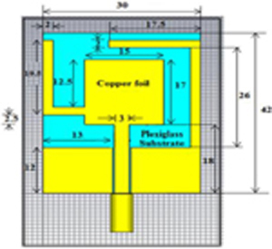
Figure 1: Geometry and dimensions of the proposed antenna.
The transparency of the antenna is achieved by using a transparent substrate having dimensions of 42302 mm in the form of Plexiglass, having a loss tangent of 0.00037 and a dielectric constant of 3.4, which is calculated using the cavity perturbation method [64, 65].
The resonance frequency of the cavity is described as follows:
| (1) |
where f is the resonant frequency, with mode numbers m, n, and p and corresponding dimensions a, b, and d; and are the relative permeability and permittivity of the cavity filling; and is the speed of light in vacuum, respectively. In this case, by using microwave cavity perturbation theory, the dielectric properties of the sample are determined by means of the differential measurement between the empty and a sample-filled cavity resonator. The permittivity of the substrate sample is described as follows:
| (2) |
where V and V are the volumes of the empty cavity and the sample inserted, f and f are the resonant frequencies of the empty cavity and the sample inserted, respectively. The conductive patch and ground are glued to the plexiglass using adhesive so as to overcome the air gap while sticking the copper foil. Furthermore, the same transparent patch antenna is integrated with a poly-silicon solar cell ground plane with a thickness of 0.2 mm and the same dimensions as the antenna substrate. Figure 2 shows the fabricated prototype of the antennas.
CST-MWS numerical simulation software based on the Finite-Difference Time-Domain (FDTD) approach is used to carry out and optimize the proposed antenna designs and simulations. In addition, the feed point is carefully selected and optimized for impedance matching. Figure 3 depicts the evolution of the proposed 5G mm-wave radiator. Figure 4 depicts the S properties during the evolution steps. The antenna design starts with a simple rectangular microstrip patch radiator, whose length and width are determined by the basic rectangular antenna equations [66].
The width W, the effective dielectric constant , effective length L, length extension L, and the actual length L of the patch can be computed as follows:
| (3) |
| (4) |
| (5) |
| (6) |
and
| (7) |
where f is the resonance frequency, c is the speed of light in free space, h is the substrate thickness, and is the relative permittivity of the dielectric substrate, respectively.
Figure 3 (a) shows a rectangular microstrip patch with a coaxial-fed that can resonate at frequencies ranging from 4.66 GHz to 5.42 GHz. Furthermore, as shown in Fig. 3 (b), two rectangular parasitic patches are integrated adjacent to the bottom of the microstrip line to cover the 3.9-4.66 GHz, 18-20.2 GHz, and 25-28.8 GHz frequency spectrums with an |S|10 dB. Furthermore, by attaching the first L-shaped strip to the right side of the rectangular parasitic patch (see Fig. 3 (c)), we obtain resonant modes with frequencies ranging from 4.28-5.04 GHz to 17-18.3 GHz, 24.8-26.3 GHz, and 33.2-38.7 GHz, respectively. Furthermore, by including the second L-shaped strip on the main radiation patch (see Fig. 3 (d)), three resonant modes covering the 4.85-6.18 GHz Wi-Fi sub-6 GHz band, 14.16-15.49 GHz, and 29.89-39.81 GHz 5G mm-wave were excited. Due to its super wide bandwidth, the simulation results show that Antenna 4 (see Fig. 3 (d)) is more suitable for use in future 5G mm-wave communications, and it is also simple in design with ease of manufacture.
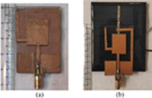
Figure 2: Photograph of the fabricated antenna: (a) Copper ground plane; (b) Solar cell ground plane.
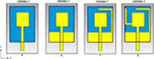
Figure 3: Evolution of the proposed patch antenna: (a) Primary rectangular patch radiator. (b) Two rectangular parasitic patches incorporated in antenna 1. (c) First L-shaped strip incorporated in antenna 2 on the right side of the rectangular parasitic patch. (d) Second L-shaped strip incorporated additionally in antenna 3 on the primary rectangular patch radiator.
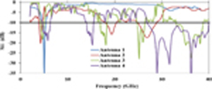
Figure 4: S characteristics during the evolution steps.
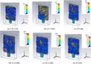
Figure 5: Snapshots of the simulated current distributions of the proposed antenna at different frequencies.
The surface current distribution of the antenna can be used to study the resonant properties of the proposed plexiglass-based transparent patch antenna with a copper ground plane. Figure 5 depicts the proposed antenna’s simulated surface current distribution at frequencies of 5.42, 15.3, 29, 31.6, 36.2, and 38 GHz, with the high-pitched color representing the strongest surface current distribution area. According to this, at 5.12 GHz, the majority of the power is radiated across the surface of the antenna’s rectangular parasitic patches and L-shaped strips, whereas at 15.3 GHz, the primary radiator, two L-shaped strips, and the right-side rectangle parasitic patch have the most power. The results demonstrate that the two L-shaped strips have the greatest influence on the formation of resonance modes in the lower and upper bands, respectively. Similarly, at 29, 31.6, 36.2, and 38 GHz, the most power is emitted on the surface of the primary radiator and rectangular parasitic patches placed near the microstrip feed, resulting in super wideband performance.
III. MEASUREMENTS AND RESULTS
The fabricated prototype, displayed in the inset of Fig. 6, was characterized in the frequency range of 1-44 GHz using a microwave vector network analyzer (serial number: KEYSIGHT N9951A). In Fig. 7, the simulated and measured |S| and VSWR responses of two cases of the proposed transparent patch antenna with the copper ground and solar cell ground are compared.

Figure 6: Snapshots of the KEYSIGHT N9951A Network Analyzer for measuring S-parameters.
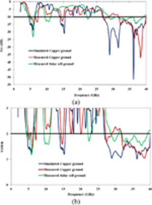
Figure 7: (a) Measured and simulated return loss |S| of the proposed antenna. (b) Measured and simulated VSWR of the proposed antenna.
Table 1 shows the measured results of the proposed antennas at the desired operating band of frequencies, allowing them to operate in the Wi-Fi and 5G operational bands. There is a reasonable accord between the experimental results and the simulated results for the proposed transparent antenna. However, some minor deviations are observed due to losses (transmitting antenna, connector, and cable loss) in the measurement setup, fabrication tolerances, and the resulting imperfections in the resulting dimensions.
Table 1: Measured results of the proposed antennas
| Antenna Type | Operating band of frequencies (GHz) | Impedance bandwidth (%) | S (dB) | VSWR |
|---|---|---|---|---|
| Transparent antenna with a copper ground plane | 5.04–7.32 | 36.89 | 14.67 | 1.44 |
| 14.35–15.11 | 5.15 | 13.04 | 1.57 | |
| 27.08–28.79 | 6.23 | 12.25 | 1.66 | |
| 31.64–39.81 | 21.34 | 37.09 | 1.04 | |
| Transparent antenna with a solar cell ground plane | 4.47–6.56 | 36.03 | 23.29 | 1.171 |
| 9.6–11.12 | 14.4 | 13.20 | 1.58 | |
| 22.14–22.71 | 2.55 | 11.57 | 1.71 | |
| 28.79–39.05 | 27.9 | 14.60 | 1.57 |
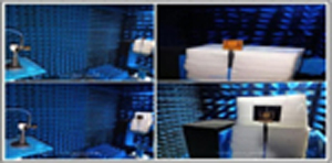
Figure 8: Photograph of the measurement environment, which includes the anechoic chamber, the standard horn antenna, and the proposed antennas.
Table 2: Simulated and measured peak gain of proposed antennas
| Frequency (GHz) |
Simulated Gain(dBi) | Measured Gain (dBi) | MeasuredGain (dBi) | Percentage errorbetween simulated andmeasured results | |
|---|---|---|---|---|---|
| Copper ground | Copper ground | Solar cell ground | Copper ground | Solar cell ground | |
| 5.5 | 8.58 | 6.74 | 11.6 | 21.44% | 35.2% |
| 28.79 | 8.14 | 5.93 | 4.94 | 27.15% | 39.3% |
| 36.7 | 10.3 | 8.09 | 5.67 | 21.45% | 44.95% |
| 38.1 | 9.99 | 12.5 | 6.38 | 25.13% | 36.14% |
Table 3: Comparison table for 5G antennas
| Ref. No. | Antenna type | Frequency ofOperation (GHz) | Antenna size (mm) | Substrate | Impedancebandwidth % | RealizedGain (dBi) |
|---|---|---|---|---|---|---|
| [2] | Handset | 25-30 | 23 X 7 X 4 | RO4350B | NR | 7 |
| [3] | MIMO | 25-38 | 17.5 X 14 X 0.254 | Rogers 5870 | 41 | 10.5 |
| [4] | MIMO | 23–39 | 6 X 8 X 0.508 | Polycarbonate | 51.6 | 7.2 dB |
| [6] | Slot array | 23-29 | 35 X 2.5 X 0.381 | Rogers 5880 | 23.07 | 12.5 |
| [7] | MIMO | 3.5*, 4.3*& 24-38 | 14 X 10 PIFA | FR4 | 11.4, 9.3 &50.9 | NR |
| [8] | SIW slot | 28.6* | 35.72 X 12 X 2.16 | Rogers 5880 | 5.6 | 7.27 |
| [9] | Proximity-coupled | 26.04-28.78 | 42.5 X 36.4 X 7.2 | Taconic TLY-5 | 9.8 | 21 |
| [10] | AiP phased | 30.4* | 6 X 6 | Organic | 2.6 | 4 |
| [11] | AiP phased | 28.27-28.97 | 3 X 3.5 X 0.55 | Stainless steel | 2.4 | 14.09 |
| [12] | MIMO | 24.25-27.5 | 31.2 X 31.2 X 1.57 | Rogers 5880 | 15.6 | 8.732 |
| [13] | MIMO | 25-30 | 18 X 12 X 0.2 | Neltec NY9220 | 18 | 11.3 |
| [14] | End-fire | 28* | 20 X 20 X 20 | Nelco NY9220 | 9 | 8-10 |
| [15] | End fire | 28-33 | 20 X 3.5 X 0.254 | Rogers 4350B | NR | 6 |
| [16] | MIMO-DGS | 25.1-37.5 | 12 X 12 X 0.8 | Rogers 5880 | 34.44 | 10.6 |
| [17] | Patch-DGS | 28-38 | 50 X 50 X 0.508 | Rogers 5880 | 32 | 18.65 |
| [18] | Metasurface | 23.7-29.2 36.7-41.1 | 6.9 X 6.9 X 1.5 | Rogers 5880 | 20.7 11.3 | 7.2 10.9 |
| [19] | Metasurface | 23.9-31.4 | 12.84 X 12.84 X 0.46 | RO4350B | 27.1 | 13.6 |
| [20] | Metamaterial | 26.58-29.31 | 18 X 22 X 0.81 | RO4003C | 9.77 | 11.94 |
| [21] | Metamaterial | 27.1-29.56 | 18 X 22 X 0.81 | RO4003 | 8.68 | 11.59 |
| [22] | Patch array | 24.35-31.13 | 7 X 6.2 X 0.508 | Rogers 5880 | 24.4 | 19.88 |
| [23] | Patch array | 25.3-30.2 | 3.5 X 3 X 0.935 | Taconic TLY-5 | 17.7 | 16.4 |
| [24] | Patch | 24-40 | 12 X 4.6 X 0.8 | Rogers 5880 | 68.06 | 19 |
| [25] | Patch array | 27-31.35 | 11 X 11 X 0.257 | HL972LF(LD) | 15 | 9.26 |
| [26] | Patch array | 25.8-29.8 | 2 X 2.2 X 1.3 | RO4003C | 14.28 | 5.5 |
| [27] | SIW Array | 24.25-29.5 | 5.3 X 5.3 X 0.254 | RO4350B, FR4 | 26.8 | 7.40.6 |
| [28] | PIFA | 24.7-29.6 | 4.5 X 4.5 X 1.3 | FR4 | 15.3 | 5.85 |
| [29] | Patch-BGA | 30.8-35.7 | 5 X 5 X 1.3 | FR4 | 15.21 | 3.2-4.2 |
| [30] | bowtie-BGA | 29.75* | 6 X 6 X 1.6 | FR4, RO4350B | 37.3 | 7.59 |
| [31] | BGA | 26.6-35.7 | 5 X 5 X 1.3 | FR4 | 29.2 | 5.2 |
| [32] | Aperture-coupled | 27-3027.4-34.2 | 15 X 15 X 0.67 | ITEQ IT-88GMW | 10.5222.1 | 7.88 |
| [33] | Patch array | 24.25-28.3537-43.5 | 18.2 X 4.1 X 1.07 | RO4350B RO4450F | 15.5817.1 | 5.86.2 |
| [35] | SIW cavity | 28* | 20.9 X 20.9 X 0.508 | Rogers 5880 | 4.6 | 16 |
| [36] | Archimedean spiral patch | 21.1-34.1 | 30 X 15 X 0.254 | Rogers 5880 | 46.4 | 6.49 |
| [37] | Dual-Array | 31.30-39 | 2.34 X 3.12 X 0.5 | Rogers 5880 | 20.26 | 16.4 |
| [38] | DRA | 24-28 | 8 X 2.4 X 2.2 | DR | 15.38 | NR |
| [39] | Phased Array | 17.7-19.3 27.3-29.1 | 55 X 110 X 0.787 | N9000 PTFE | 8.896.42 | 13.5 15.5 |
| Proposed 5Gantenna | Patch | 5.04-7.3214.35-15.1127.08-28.7931.64-39.81 | 42 X 30 X 2 | Plexiglass | 36.895.156.2321.34 | 6.745.938.0912.5 |
Resonant frequency NR-Not Reported SIW-Substrate-integrated waveguide
Table 4: Comparison table for super-solar integrated antennas
| Ref. No. | Frequency ofOperation (GHz) | Antenna Patch size (mm) | Substrate | Impedance bandwidth % | RealizedGain (dBi) |
|---|---|---|---|---|---|
| [49] | 2.61* | 35.0 X 40.8 | Cover glass | NR | 8.4 |
| [50] | 2.461-2.476 | 30.5 X 30.5 | Cover glass | 2 | 5.15 |
| [51] | 2.43* | 25.15 X 25.15 | Borosilicate glass | 7.25 | 4.4 |
| [52] | 2.45* | 26.8 X 24.1 | Borosilicate glass | NR | 5 |
| [54] | 2.33-10.8 | 45 X 31 | Acrylic | NR | 4.1 |
| [55] | 11.7-12.2214.0-14.5 | 18 X 15 | Plexiglas | NR | 6.05 7.61 |
| [56] | 10* | 97 X 75 | AF32 glass | NR | 4.1 |
| [57] | 3.4–3.8 | 85 X 55 | Perspex & Glass | 4.3 | 3.96 |
| [58] | 2.2-12.1 | 44.6 X 25.5 | Glass | NR | 3-5 |
| [59] | 8.51-9.10 | 157 X 157 | Glass | 35 | 20.14 |
| [61] | 25* | 110 X 80 | Soda lime glass | NR | 41.3 |
| [62] | 0.4435–0.455 | 80 X 40 | Rogers Duroid 5880 | 2.55 | 2.5 |
| Proposedantenna withsolar cell | 4.47-6.569.6-11.1222.14-22.7128.79-39.05 | 42 X 30 | Plexiglass | 36.03%14.4%2.55%27.9% | 11.64.945.676.38 |
NR-Not Reported Resonant frequency
Table 5: Performance of the proposed antennas with and without integration
| Ref. No. | Antenna parameter | Antenna with solar cells | Antenna without solar cells | Solar cell parameter | Solar cell with antenna | Solar cell without antenna |
|---|---|---|---|---|---|---|
| [51] | Gain | 4.4 dBi | 4.9 dBi | P | NR | NR |
| [52] | NR | NR | NR | 76 % | 78 % | |
| [54] | NR | NR | NR | P | 65.5 mW13.1 % | NR |
| [55] | Gain | 6.79 dBi | 8.05 dBi | P | 10.23 W | 12.42 W |
| [56] | Gain | 4.1 dB | 6.4 dB | 17.4 % | 18 % | |
| [57] | Gain | 3.96 dBi | NR | P | NR | 345.6 mW |
| [58] | Return loss | 29 dB | 33 dB | V | 74.4 mV | 76.1 mV |
| [59] | Efficiency | 38.8 % | NR | VI | 0.571 V1.80 A | 0.576 V1.84 A |
| [61] | Efficiency | 80% | NR | P | 1020 mW | NR |
| Proposed antenna with solar cell | Gain | 11.6 dBi(4.47-6.56 GHz) | 6.74 dBi(5.04-7.32 GHz) | P | 238.24 mW | 423.69 mW |
| 4.94 dBi(9.6-11.12 GHz) | 5.93 dBi(14.35-15.11 GHz) | |||||
| 5.67 dBi(22.14-22.71 GHz) | 8.09 dBi(27.08-28.79 GHz) | |||||
| 6.38 dBi(28.79-39.05 GHz) | 12.5 dBi(31.64-39.81 GHz) |
NR-Not Reported V-Output voltage
The far-field radiation patterns are measured in an anechoic room with a standard horn antenna. Figure 8 shows the antenna under test (AUT) in the anechoic chamber. For pattern characteristics measurement, the transmitting horn antenna and test antenna (TA) were separated by a distance of 4 m. Now, the E-plane radiation patterns of the proposed transparent antenna were estimated by both simulation and experiment. They were then plotted in Figs. 9 (a)-(d) for frequencies of 5.5, 28.79, 36.7, and 38.1 GHz, respectively. A good correlation is achieved between simulated and measured omnidirectional radiation patterns. Table 2 shows the simulated and measured peak gains of proposed antennas at the desired operating band of frequencies.
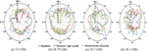
Figure 9: Gain radiation pattern of the proposed antenna for (a) 5.5 GHz, (b) 28.79 GHz, (c) 36.7 GHz, (d) 38.1 GHz.
A dedicated set of measurements to evaluate the effects of the proposed patch integrated into the photovoltaic generation of solar cells is also described. The open-circuit voltage (V) and short-circuit current (I) of solar cells are measured under the midday sun to assess the shading effect on solar photovoltaic output, as illustrated in Fig. 10.

Figure 10: Measurement of V and I of the solar cell with and without antenna integration.
From the measurement, the solar cell carries the current I = 97.4 mA with the voltage V = 4.35 V when there is no integrated antenna with the solar cell. Nevertheless, the identical solar cell is integrated with an antenna; the measured I current and V voltage are 61.4 mA and 3.88 V, respectively. The open-circuit voltage has a small difference, as expected because a relatively stable open-circuit voltage is a feature of solar cells in partially shaded scenarios. The small decrease in short-circuit current mismatches the theoretical transparency, which may be caused by non-strict conditions of measurement. The voltage-current (VI) characteristic of solar cells integrated with and without antennas is shown in Fig. 11. When sunlight strikes a solar cell, it emits photons, which are tiny bundles of energy whose energy is higher than the energy gap and which provide electrons and holes in the depletion area with energy. They function as a battery while the electrons are directed towards the N-type and the holes towards the P-type. This flow of electrons and holes creates a negative current in a short circuit. The same maximum current and voltage may be maintained beyond the short-circuit current and open-circuit voltage by attaching an external battery in reverse bias and forward bias circumstances, respectively.

Figure 11: The V-I characteristics of a solar cell with and without an antenna.
The maximum useful power is the area of the largest rectangle that can be formed under the V-I curve. If V and I are the values of voltage and current under this condition, then the maximum power (P) can be computed as follows:
| (8) |
The observed maximum power (P) of the solar cell without and with the antenna is 423.69 mW and 238.24 mW, which is a slight decrease in maximum output DC power of 185.456 mW and also commonly acceptable.
A comparison of a list of reviewed 5G antennas and solar-integrated antenna designs may be found in Table 3 and Table 4. A comparison of solar-integrated antennas with and without a built-in solar panel is shown in Table 5 below.
IV. CONCLUSION
A compact parasitic patch loaded transparent patch antenna with the ground plane of both copper conductor and the solar cell was fabricated and tested, presenting a commendable agreement between simulation and measurement for 5G mm-wave applications. The proposed super solar patch antenna operates at the measured frequency bands of 4.47-6.56 GHz, 9.6-11.12 GHz, 22.14-22.71 GHz, and 28.79-39.05 GHz, covering the required sub-6 GHz and beyond 6 GHz mm-wave 5G frequency bands. When the proposed antenna is compared to other published results in the literature, the proposed antenna provides remarkable enhancements in terms of gain, bandwidth, and size reduction. Additionally, the performance of the proposed antenna is assessed with the embedding of a solar cell as a ground. It is found that the antenna performance in terms of S and VSWR has not been affected. The performance of the used solar cell is measured in terms of V-I characteristics to show no major effects on solar energy harvesting. The proposed solar integrated antenna will aid in the future engineering evolution of the low-profile microstrip patch antenna to satisfy the demands of mm-wave green wireless applications.
ACKNOWLEDGMENTS
The authors would like to thank Tamil Nadu State Council for Science and Technology (http://www.tanscst.nic.in/) for sponsoring this work (EEE-1326) under short-term Grants SPS 2021-2022.
REFERENCES
[1] R. Dangi, P. Lalwani, G. Choudhary, I. You, and G. Pau, “Study and investigation on 5G technology: A systematic review,” Sensors, vol. 22, no. 1, pp. 1-32, 2021.
[2] J. Kurvinen, H. Kähkönen, A. Lehtovuori, J. Ala-Laurinaho, and V. Viikari, “Co-designed mm-wave and LTE handset antennas,” IEEE Trans. Antennas Propag., vol. 67, no. 3, pp. 1545-1553, 2019.
[3] M. I. Magray, G. S. Karthikeya, K. Muzaffar, and S. K. Koul, “Corner bent integrated design of 4G LTE and mm-wave 5G antennas for mobile terminals,” Prog. Electromagn. Res. M, vol. 84, pp. 167-175, 2019.
[4] I. S. Masoodi, I. Ishteyaq, K. Muzaffar, and M, I. Magray, “Low-cost substrate based compact antennas for 4G/5G side-edge panel smartphone applications,” Prog. Electromagn. Res. Lett., vol. 91, pp. 145-152, 2020.
[5] J. Khan, D. A. Sehrai, and S. Ahmad, “Design and performance comparison of metamaterial-based antenna for 4G/5G mobile devices,” Int. J. Electron. Commun. Eng., vol. 12, no. 6, pp. 382-387, 2018.
[6] M. Ikram, E. A. Abbas, N. Nguyen-Trong, K. H. Sayidmarie, and A. Abbosh, “Integrated frequency-reconfigurable slot antenna and connected slot antenna array for 4G and 5G Mobile handsets,” IEEE Trans. Antennas Propag., vol. 67, no. 12, pp. 7225-7233, 2019.
[7] N. Kumar and R. Khanna, “A two element MIMO antenna for sub-6 GHz and mm-Wave 5G systems using characteristics mode analysis,” Microw. Opt. Technol. Lett., pp. 1-9, Sep. 2020.
[8] R. B. Di Renna, V. P. R. M. Souza, T. N. Ferreira, L. J. Matos, J. A. M. Souza, and G. L. Siqueira, “A new double-sided substrate-integrated waveguide slot array antenna for 5G applications,” Microw. Opt. Technol. Lett., vol. 61, no. 3, pp. 1-6, 2018.
[9] H. A. Diawuo and Y.-B. Jung, “Broadband proximity-coupled microstrip planar antenna array for 5G cellular applications,” IEEE Antennas Wirel. Propag. Lett., vol. 17, no. 7, pp. 1286-1290, 2018.
[10] D. Liu, X. Gu, C. W. Baks, and A. Valdes-Garcia, “Antenna-in-package design considerations for Ka-band 5G communication applications,” IEEE Trans. Antennas Propag., vol. 65, no. 12, pp. 6372-6379, 2017.
[11] J. Park, D. Choi, and W. Hong, “Millimeter-wave phased-array antenna-in-package (AiP) using stamped metal process for enhanced heat dissipation,” IEEE Antennas Wirel. Propag. Lett., vol. 18, no. 11, pp. 2355-2359, 2019.
[12] N. Shoaib, S. Shoaib, R. Y. Khattak, I. Shoaib, X. Chen and A. Perwaiz, “MIMO antennas for smart 5G devices,” IEEE Access, vol. 6, pp. 77014-77021, 2018.
[13] Z. Wani, M. P. Abegaonkar, and S. K. Koul, “Millimeter-wave antenna with wide-scan angle radiation characteristics for MIMO applications,” Int. J. RF Microw. Comput. Aided Eng., vol. 29, no.5, pp. 1-9, 2019.
[14] G. S. Karthikeya, S. K. Koul, Ajay K. Poddar, and U. Rohde, “Ultra-compact orthogonal pattern diversity antenna module for 5G smartphones,” Microw. Opt. Technol. Lett., pp. 1-10, Mar. 2020.
[15] R. M. Moreno, J. Ala-Laurinaho, A. Khripkov, J. Ilvonen, and V. Viikari, “Dual-polarized mm-wave end-fire antenna for mobile devices,” IEEE Trans. Antennas Propag., vol. 68, no. 8, pp. 5924-5934, 2020.
[16] S. F. Jilani, and A. Alomainy, “Millimetre-wave T-shaped MIMO antenna with defected ground structures for 5G cellular networks,” IET Microw. Antennas Propag., vol. 12, no. 5, pp. 672-677, 2018.
[17] K. R. Mahmoud and A. M. Montaser, “Optimised 4 4 millimetre-wave antenna array with DGS using hybrid ECFO-NM algorithm for 5G mobile networks,” IET Microw. Antennas Propag., vol. 11, no. 11, pp. 1516-1523, 2017.
[18] T. Li and Z. N. Chen, “A dual-band metasurface antenna using characteristic mode analysis,” IEEE Trans. Antennas Propag., vol. 66, no. 10, pp. 5620-5624, 2018.
[19] W. Wan, M. Xue, L. Cao, T. Ye, and Q. Wang, “Low-profile broadband patch-driven metasurface antenna,” IEEE Antennas Wirel. Propag. Lett., vol. 19, no. 7, pp. 1251-1255, 2020.
[20] M. J. Jeong, N. Hussain, J. W. Park, S. G. Park, S. Y. Rhee, and N. Kim, “Millimeter-wave microstrip patch antenna using vertically coupled split ring metaplate for gain enhancement,” Microw. Opt. Technol. Lett., pp. 1-6, 2019.
[21] M. Jeong, N. Hussain, A. Abbas, S. Y. Rhee, S. M. Lee, S.-K. Gil and N. Kim, “Performance improvement of microstrip patch antenna using a novel double-layer concentric rings metaplate for 5G millimeter wave applications,” Int. J. RF Microw. Comput. Aided Eng., vol. 31, no. 2, pp. 1-10,2020.
[22] M. Khalily, R. Tafazolli, P. Xiao, and A. A. Kishk, “Broadband mm-wave microstrip patch array antenna with improved radiation characteristics for different 5G applications,” IEEE Trans. Antennas Propag., vol. 66, no. 9, pp. 4641-4647, 2018.
[23] J. Xu, W. Hong, Z. H. Jiang, and H. Zhang, “Wideband, low-profile patch array antenna with corporate stacked microstrip and substrate integrated waveguide feeding structure,” IEEE Trans. Antennas Propag., vol. 67, no. 2, pp. 1368-1373,2019.
[24] P. Ramanujam, C. Arumugam, R. Venkatesan, and M. Ponnusamy, “Design of compact patch antenna with enhanced gain and bandwidth for 5G mm-wave applications,” IET Microw. Antennas Propag., vol. 14, no. 12, pp. 1455-1461, 2020.
[25] M. Xue, W. Wan, Q. Wang, and L. Cao, “Low-profile millimetre-wave wideband microstrip antenna with parasitic patch arrays,” IET Microw. Antennas Propag., vol. 15, pp. 364-370,2021.
[26] M. S. Rahimi, E. V. Pinto dos Anjos, P. Taghikhani, and V. Volski, “A cost-efficient 28 GHz integrated antenna array with full impedance matrix characterization for 5G NR,” IEEE Antennas Wirel. Propag. Lett., vol. 19, no. 4, pp. 666-670, 2020.
[27] I. L. de Paula, S. Lemey, D. Bosman, Q. Van den Brande, O. Caytan, J. Lambrecht, M. Cauwe, G. Torfs, and H. Rogier, “Cost-effective high-performance air-filled SIW antenna array for the global 5G 26 GHz and 28 GHz bands,” IEEE Antennas Wirel. Propag. Lett., vol. 20, no. 2, pp. 194-198, 2021.
[28] X. Wang, X. Liu, W. Zhang, D. Hao, and Y. Liu, “Surface-mount PIFA using ball grid array packaging for 5G mm-Wave,” Prog. Electromagn. Res. Lett., vol. 98, pp. 55-60, 2021.
[29] X. Wang, X. Liu, W. Zhang, D. Hao, and Y. Liu, “Surface mounted microstrip antenna using ball grid array packaging for mm-Wave systems integration,” Prog. Electromagn. Res. Lett., vol. 98, pp. 105-111, 2021.
[30] X. Liu, W. Zhang, D. Hao, and Y. Liu, “Surface-mount bowtie antenna element for millimeter-wave applications,” Microw. Opt. Technol. Lett., pp. 1-7, 2020.
[31] X. Liu, W. Zhang, D. Hao, and Y. Liu, “Cost-effective surface-mounted patch antenna with ring slot using ball grid array packaging for 5G millimeter-wave applications,” Prog. Electromagn. Res. Lett., vol. 99, pp. 127-133, 2021.
[32] N. -C. Liu and J. -H. Tarng, “Double-curved metal in multilayer printed circuit boards for bandwidth enhancement of millimeter-wave patch antennas,” IEEE Trans. Compon. Packag. Manuf. Technol., vol. 11, no. 7, pp. 1088-1096, 2021.
[33] Y. He, S. Lv, L. Zhao, G. -L. Huang, X. Chen, and W. Lin, “A Compact dual-band and dual-polarized millimeter-wave beam scanning antenna array for 5G mobile terminals,” IEEE Access, vol. 9, pp. 109042-109052, 2021.
[34] R. Mittra, A. Nasri, and R. Kumar Arya, “Wide-Angle Scanning Antennas for Millimeter-Wave 5G Applications,” Engineering, vol. 11, pp. 60-71, 2022.
[35] M. Asaadi and A. Sebak, “High-gain low-profile circularly polarized slotted SIW cavity antenna for MMW applications,” IEEE Antennas Wirel. Propag. Lett., vol. 16, pp. 752-755, 2017.
[36] H. Chen, Y. Shao, Y. Zhang, C. Zhang, and Z. Zhang, “A low-profile broadband circularly polarized mm-wave antenna with special-shaped ring slot,” IEEE Antennas Wirel. Propag. Lett., vol. 18, no. 7, pp. 1492-1496, 2019.
[37] H. U. Tahseen, L. Yang, and W. Hongjin, “A dual-array antenna system for 5G millimeter-wave applications,” Applied Computational Electromagnetics Society (ACES) Journal, vol. 36, no. 10, pp. 1319-1324, 2021.
[38] N. F. Sallehuddin, M. H. Jamaluddin, M. R. Kamarudin, and M. H. Dahri, “Reflectarray resonant element based on a dielectric resonator antenna for 5G applications,” Applied Computational Electromagnetics Society (ACES) Journal, vol. 36, no. 7, pp. 844-851, 2021.
[39] N. O. Parchin, O. M. Dardeer, A. S.I. Amar, C. H. See, and R. Abd-Alhameed, “Dual-band phased array 5G mobile-phone antenna with switchable and hemispherical beam pattern coverage for MIMO-diversity communications,” Applied Computational Electromagnetics Society (ACES) Journal, vol. 36, no. 12, pp. 1602-1609,2021.
[40] M. Tanaka, Y. Suzuki, K. Araki, and R. Suzuki, “Microstrip antenna with solar cells for microsatellites,” Electronics Letters, vol. 31, no. 1, pp. 5-6, 1995.
[41] T. N. Suresh babu and D. Sivakumar, “Stepped slot patch antenna with copper ground plane and solar cell ground plane for future mobile communications,” Prog. Electromagn. Res. C, vol. 98, pp. 187-198, 2020.
[42] S. Vaccaro, C. Pereira, J. R. Mosig, and P. de Maagt, “In-flight experiment for combined planar antennas and solar cells (SOLANT),” IET Microw. Antennas Propag., vol. 3, no. 8, pp. 1279-1287,2009.
[43] S. V. Shynu, J. Roo Ons Maria, J. Ammann Max, and B. Norton, “Dual band a-Si:H solar-slot antenna for 2.4/5.2 GHz WLAN applications,” Radioengineering, vol. 18, no. 4, pp. 354-358,2009.
[44] O. Yurduseven and D. Smith, “A solar cell stacked multi-slot quad-band PIFA for GSM, WLAN and WiMAX networks,” IEEE Microw.Wireless Compon.Lett., vol. 23, no. 6, pp. 285-287,2013.
[45] O. Yurduseven and D. Smith, “Solar cell stacked dual-polarized patch antenna for 5.8 GHz band WiMAX network,” Electronics Letters, vol. 49, no. 24, pp. 1514-1515, 2013.
[46] R. Caso, A. D’Alessandro, A. Michel, and P. Nepa, “Integration of slot antennas in commercial photovoltaic panels for stand-alone communication systems,” IEEE Trans. Antennas Propag., vol. 61, no. 1, pp. 62-69, 2013.
[47] M. Elsdon, O. Yurduseven, and X. Dai, “Wideband metamaterial solar cell antenna for 5 GHz Wi-Fi communication,” Prog. Electromagn. Res. C, vol. 71, pp. 123-131, 2017.
[48] B. Bai, Z. Zhang, X. Li, C. Sun, and Y. Liu, “Integration of microstrip slot array antenna with dye-sensitized solar cells,” Sensors, vol. 20, no. 6257, pp. 1-13, 2020.
[49] T. W. Turpin and R. Baktur, “Meshed patch antennas integrated on solar cells,” IEEE Antennas Wirel. Propag. Lett., vol. 8, pp. 693-696, 2009.
[50] T. Yasin and R. Baktur, “Circularly polarized meshed patch antenna for small satellite application,” IEEE Antennas Wirel. Propag. Lett., vol. 12, pp. 1057-1060, 2013.
[51] S. Sheikh, “Circularly polarized meshed patch antenna,” IEEE Antennas Wirel. Propag. Lett., vol. 15, pp. 352-355, 2016.
[52] KS. K. Podilchak, D. Comite, B. K. Montgomery Brendan, Y. Li, V. Gómez-Guillamón Buendía, and Y. M. M. Antar, “Solar-panel integrated circularly polarized meshed patch for cubesats and other small satellites,” IEEE Access, vol. 7, no. 96560-96566, 2019.
[53] T. Yasin, R. Baktur, T. Turpin, and J. Arellano, “Analysis and design of highly transparent meshed patch antenna backed by a solid ground plane,” Prog. Electromagn. Res. M, vol. 56, pp. 133-144, 2017.
[54] O. Yurduseven, D. Smith, and M. Elsdon, “UWB meshed solar monopole antenna,” Electronics Letters, vol. 49, no. 9, 2013.
[55] F. Nashad, S. Foti, D. Smith, M. Elsdon, and O. Yurduseven, “Ku-band suspended meshed patch antenna integrated with solar cells for remote area applications,” Prog. Electromagn. Res. C, vol. 83, pp. 245-254, 2018.
[56] T. Yekan and R. Baktur, “An X band patch antenna integrated with commercial triple-junction space solar cells,” Microw. Opt. Technol. Lett., vol. 59, no. 2, Dec. 2017.
[57] M. J. Roo-Ons, S. V. Shynu, M. J. Ammann, S. J. McCormack, and B. Norton, “Transparent patch antenna on a-Si thin-film glass solar module,” Electronics Letters, vol. 47, no. 2, pp. 85-86, 2011.
[58] T. Peter, T. A. Rahman, S. W. Cheung, R. Nilavalan, H. F. Abutarboush, and A. Vilches, “A novel transparent UWB antenna for photovoltaic solar panel integration and RF energy harvesting,” IEEE Trans. Antennas Propag., vol. 62, no. 4, pp. 1844-1853, 2014.
[59] B. Xi, X. Liang, Q. Chen, K. Wang, J. Geng, and R. Jin, “Optical transparent antenna array integrated with solar cell,” IEEE Antennas Wirel. Propag. Lett., vol. 19, no. 3, pp. 457-461, 2020.
[60] P. Dreyer, M. Morales-Masis, S. Nicolay, C. Ballif, and J. Perruisseau-Carrier, “Copper and transparent-conductor reflectarray elements on thin-film solar cell panels,” IEEE Trans. Antennas Propag., vol. 62, no. 7, pp. 3813-3818, 2014.
[61] Y.n-S. Chen, Y.-H. Wu, and C.-C. Chung, “Solar-powered active integrated antennas backed by a transparent reflectarray for cubesat applications,” IEEE Access, vol. 8, no. 137934-137946,2020.
[62] T. Alam, A. F. Almutairi, M. Samsuzzaman, M. Cho, and M. T. Islam, “Metamaterial array-based meander line planar antenna for cube satellite communication,” Scientific Reports, vol. 11, no. 14087, pp. 1-12, 2021.
[63] S. B. T. Naganathan and S. Dhandapani, “Patch antenna integrated on solar cells for green wireless communication: A feature oriented survey and design issues,” Int. J. RF Microw. Comput. Aided Eng., vol. 32, no. 1, pp. 1-29, 2021.
[64] A. Kumar and S. Sharma, “Measurement of dielectric constant and loss factor of the dielectric material at microwave frequencies,” Prog. Electromagn. Res., vol. 69, pp. 47-54, 2007.
[65] C. Steiner, S. Walter, V. Malashchuk, G. Hagen, I. Kogut, H. Fritze, and R. Moos, “Determination of the dielectric properties of storage materials for exhaust gas aftertreatment using the microwave cavity perturbation method,” Sensors, vol. 20, pp. 1-18, 2020.
[66] R. Garg, P. Bhartia, I. Bahl, and A. Ittipiboon, Microstrip Antenna Design Handbook, Artech House inc., Norwood, January 2001.
BIOGRAPHIES

Suresh Babu T. Naganathan received a B.E. degree in Electronics and Communication Engineering from Madurai Kamaraj University, India, in 1997 and an M.E. degree in Power Electronics and Drives from Anna University, India, in 2009, respectively. He is currently working as an Assistant Professor in the Department of Electronics and Communication Engineering at Adhiparasakthi Engineering College, Tamilnadu, India. His research interests include those in the areas of electromagnetics, antenna design, and wave propagation.

Sivakumar Dhandapani received a B.E. degree in Electronics and Communication Engineering from the University of Madras, India, in 1995, an M.E. degree in Process Control and Instrumentation from Annamalai University, India, in 2002, and the Ph.D. degree in Faculty of Information and Communication from Anna University, India, in 2010, respectively. He is now a Professor at AMET University, Tamil Nadu, India.

Thirumaraiselvan Packirisamy received B.E. degree in Electronics and Communication Engineering from Allagappa Chettiar College of Engineering and Technology, Karaikudi in 1992 and M.E. degree in Telecommunication Engineering from Multimedia University, Malaysia in 2006. He completed Ph.D. in Information and Communication Engineering at Anna University, Chennai in 2018. He has more than 30 years of experience in teaching and research and currently working as Professor in Adhiparasakthi Engineering College, Melmaruvathur. His research interests include Wireless Communication, Body Area Networks, Electromagnetic Wave Propagation and Biomedical Engineering. He has published several research papers in reputed journals and international conferences.
ACES JOURNAL, Vol. 37, No. 10, 1039–1050
doi: 10.13052/2022.ACES.J.371004
© 2022 River Publishers