Metamaterial Loaded Compact Multiband Monopole Antenna for Wireless Applications
Shiney Thankachan1, Binu Paul1, Anju Pradeep1, Pezholil Mohanan2, and Remsha Moolat2
1Department of Electronics and Communication Engineering, School of Engineering, Cochin University of Science and Technology, Kochi-22, Kerala, India
shineythankachan@gmail.com
2Department of Electronics, Cochin University of Science and Technology, Kochi-22, Kerala, India
Submitted On: March 30, 2021; Accepted On: June 20, 2022
Abstract
This paper proposes the design of a compact monopole antenna loaded with metamaterial (MTM), for multiband operation for wireless local area network (WLAN) and Worldwide Interoperability for Microwave Access (WiMAX) applications. The monopole antenna is originally designed to operate in 2.8 GHz and 6 GHz The placement of MTM yields one additional band at 3.5 GHz corresponding to WiMAX with a shift in frequency of the original monopole to the WLAN frequencies of 2.4 GHz and 5.5 GHz with improved matching at the higher band. Dependencies of resonant frequencies on various parameters are formulated through regression analysis and a design equation for the proposed antenna is developed. The full-wave simulation and design equation of the three resonances show a negligible difference. A comparative study of the developed monopole with reported antennas shows that the developed structure is compact with an overall dimension of 19 x 31 mm2. The measured results of the antenna show good impedance bandwidth of 6.25%, 24.57%, and 16.54% for the three bands centered at 2.4, 3.5, and 5.5 GHz The antenna compactness is obtained due to metamaterial loading. All the simulated radiation characteristics of the proposed antenna are validated experimentally. The proposed antenna obtains a compact electrical size of 0.248x0.152 at 2.4 GHz with multi-band operations at frequencies 2.4 GHz, 3.5 GHz, and 5.5 GHz corresponding to WLAN and WiMAX.
Index Terms: Double negative material (DNG), metamaterial (MTM), monopole antenna, multiband antenna, WLAN, WiMAX.
1 INTRODUCTION
Multiband operation using a single antenna system is the basic need of modern wireless communication. Multiband antennas operating for wireless local area network (WLAN) and Worldwide Interoperability for Microwave Access (WiMAX) applications are one solution to the above problem. Several methods such as alteration of the ground plane, cutting slots on radiating patches, fractal antenna design, and use of metamaterial (MTM) structures have been suggested and explained for the design and development of multiband antennas [1–25] that could meet the requirements of modern wireless communication systems to a certain extent. System compactness and interference minimization can be achieved by using multiband antennas over ultra wideband antennas (UWB).
The era of multi-band operation developed through defected ground structure [1–2], providing multiple slots on radiator or ground [3–6], by the addition of metal strips [7–8], and also by adding strips and slots [9–12]. A rectangular patch antenna is made electrically small by engineering the patches of square and circular shape cuts [13]. By etching a rectangular slot in the ground plane and adding a fork-shaped strip in a modified rectangular ring, the antenna produced three resonant modes [14]. A recent development in the field is a triple-band modified Hilbert curve fractal antenna [15].
Metamaterials are artificial materials. The growing interest in the study of MTM applications in antenna development is due to the attractive properties such as negative permittivity and permeability possessed by the MTM. These properties of metamaterials help to improve the antenna performance such as miniaturization, gain, and bandwidth. Also, the use of metamaterials in multiband antenna design aids in increasing the number of operating frequencies. In antennas, metamaterials are used in different ways for obtaining multi-band operation. Single-cell MTM loading in monopole antenna results in dual-band operation for WLAN/WiMAX applications [16]. Complementary split ring resonators are loaded on a rectangular monopole antenna for producing multi-band operation [17]. Similarly, MTM cells and slots are loaded on the ground for obtaining multiband operation in a dual-band monopole antenna [18]. Another way of using MTM for multiband operation is etching a meandering split-ring slot on printed antennas [19]. MTM-inspired antennas are yet another method of using MTM for multi-band operation. Triple-band MTM-inspired antenna has been designed and analyzed using FDTD [20]. Compact metamaterial multiband antennas for wireless applications have been reported in [21–22]. Two novel tri-band metamaterial antennas are proposed with TER and CTER [23]. Active devices are used on metamaterials for obtaining wideband operation [24].
All the above-mentioned antennas exhibit good multi-band performance, but they are somewhat complicated in structure. The design of a simple compact multiband antenna operating at 2.4 GHz, 3.5 GHz, and 5.5 GHz with good radiation characteristics is the objective of this paper. The designed antenna is experimentally validated. The proposed multiband antenna overcomes the drawbacks of existing antenna designs by the combination of a monopole antenna and a double negative (DNG) metamaterial structure. This simple and compact design will provide desirable radiation characteristics in the required band as mentioned earlier.
2 MULTIBAND ANTENNA DESIGN
The evolution of the proposed antenna on FR4 substrate with a relative permittivity of 4.4, loss tangent of 0.02, and thickness of 1.6 mm with an overall size of 31 x 19 x 1.6 mm (0.407 x 0.25 x 0.021; is the wavelength in the substrate at 2.4 GHz) is detailed in the following procedural steps. It is derived from a simple monopole antenna operating in two bands, with the modified ground and a DNG structure as shown in Fig. 1.
1) A simple monopole with length L3 as /2 of the frequency 2.8 GHz is placed on one side of the substrate. The monopole is loaded with an optimized stub of dimensions 2.5 mm x 4.25 mm to improve the impedance matching.
2) A DNG structure with inner radius R1= 6.5 mm and outer radius 6.85 mm with two stubs of length 6.3 mm is etched on the backside of the monopole. The dimensions can be optimized as explained in section 3 to excite MTM behavior.
3) The ground plane dimensions of the antenna are optimized for good matching on the chosen substrate and are shown in Table 1.
The monopole along with the defective ground is resonating at two frequencies 2.8 GHz and 6 GHz as shown in Fig. 2.
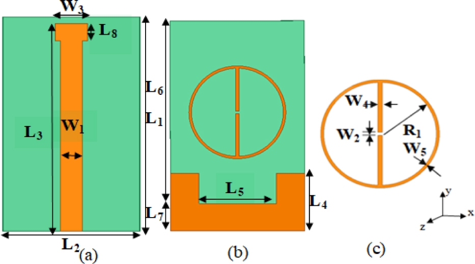
Figure 1: The proposed Antenna (a) Front View, (b) Back View, and (c) MTM unit cell.
Table 1: Design parameters of the proposed antenna
| Parameters | L1 | L2 | L3 | L4 | L5 |
| Size (mm) | 31 | 19 | 30 | 8.5 | 11 |
| Parameters | L6 | L7 | L8 | W1 | W2 |
| Size (mm) | 27 | 4 | 2.5 | 3 | 0.4 |
| Parameters | W3 | W4 | W5 | R1 | |
| Size (mm) | 4.25 | 0.5 | 0.35 | 6.5 |
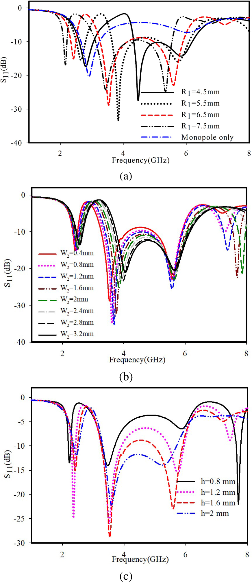
Figure 2: Simulated S11 of the proposed antenna (a) variation of R1, (b) variation of W2, (c) variation of h.
When an MTM cell is introduced into the monopole antenna, resonances are obtained at three frequencies 2.4 GHz, 3.5 GHz, and 5.5 GHz corresponding to WLAN and WiMAX applications. Since relative permittivity and relative permeability are two parameters that influence the wave propagation through a medium, alteration of these parameters changes the resonant frequencies of the antenna. On placing the MTM structure with DNG property on the monopole antenna, the substrate parameters and hence the resonant frequencies of the antenna change. The placement of MTM also produces one additional resonance and improves the S in the higher band. MTM size and position optimization are done in ANSYS HFSS. The optimal position for an MTM unit cell is at the center of the overall geometry. When the radius of the MTM structure is altered, the antenna becomes tunable to different resonant frequencies.
The parametric analysis of the radius variation (R1), gap (W2), and substrate thickness (h) are shown in Fig. 2. The antenna tuning over a wide range in three bands is possible through radius alterations as shown in Fig. 2 (a). Further fine-tuning of operating frequencies can be achieved by changing the gap between the stubs shown in Fig. 2 (b). Variation in substrate thickness (h) results in improved matching and bandwidth enhancement of three bands (Fig. 2 (c)).
3 MTM DESIGN
It is already stated in [26] that antenna miniaturization can be achieved by changing the relative permittivity and permeability. To lower the operating band of the chosen monopole, it is loaded with an MTM unit cell. The proposed MTM is a planar double negative material in which both permittivity and permeability are negative at 2.4 GHz and 5.5 GHz Fig. 4 shows the retrieved results of the refractive index (n) and impedance (z). The magnitude of n and z are retrieved from S11 and S21 characteristics of MTM, which are simulated using ANSYSHFSS, and the parameters are retrieved using the s-parameter retrieval method [27–29].
To extract the S11 and S21 characteristics of MTM, a two-port waveguide configuration as shown in Fig. 3 can be used. For this boundary conditions are to be applied in such a way that the walls of the waveguide use a pair each, of both perfect magnetic conductor (PMC) and perfect electric conductor (PEC) along the planes x-y and x-z respectively. MTM structure is modeled as PEC on a dielectric slab located at the center of the waveguide.
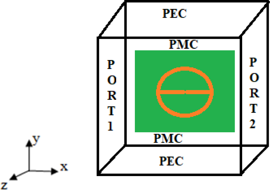
Figure 3: MTM unit cell simulation model with boundary conditions and excitations.
Two waveguide ports are placed parallel to y-z planes. Then the input wave is launched from port1 and S11 and S21 are determined. Using these values, refractive index, impedance, permittivity, and permeability can be retrieved by S-parameter retrieval method using the following equations [29]. These equations are implemented in MATLAB.
| (1) |
| (2) |
| (3) |
Where k is the wavenumber of the incident wave in free space, m is an integer which represents branch index of refractive index. Relative permittivity and relative permeability can be calculated using the relations (4) and (5).
| (4) |
| (5) |
Figure 4 shows the extracted values of relative permittivity , relative permeability , refractive index n, and impedance z. It can be observed in Fig. 4 (a) that, at 2.4 and 5.5 GHz, both permittivity and permeability show negative values. In Fig. 4 (b) the DNG property is exhibited at desired bands of 2.4 GHz and 5.5 GHz where n is negative. A passive material shows DNG behavior when its n shows negative values and z shows positive values. This proves the designed MTM can be used for miniaturisation of antennas in these two bands.
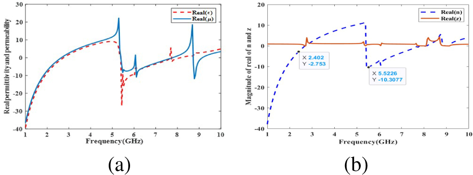
Figure 4: (a) Retrieved results for relative permittivity , relative permeability . (b) Retrieved results for refractive index n and impedance z.
4 REGRESSION ANALYSIS
The data derived from the full-wave simulation of the proposed structure was subjected to regression analysis. Dependencies of resonant frequencies on various parameters are formulated through the regression analysis and they are explained as follows. The regression equations are computed using the input values for L3 and R1 in a millimeter scale and the resulting resonance frequency values are in GHz.
4.1 First resonance
The first resonance of the proposed antenna is affected by monopole length, substrate permittivity, and size of the MTM structure. Therefore the first resonance (f) can be calculated by:
| (6) |
The regression analysis gives the variable dependencies on the first resonance through equation (6) with 98% accuracy. The design method is validated through a comparative study done on the data from full-wave simulation and those calculated using a regression equation for various values of L, and R. The resonant frequencies calculated from the design equation agree well with the simulated results. L, and R parameters show equal correlation with the first resonance, in the correlation analysis.
4.2 Second resonance
The L, and R parameters also affect the second resonance of the proposed antenna. The second resonance (f) can be calculated by:
| (7) |
The regression analysis gives the variable dependencies on the second resonance through equation (7) with 87% accuracy. The comparative study between simulated results and the design equation for the second resonance shows good agreement.
4.3 Third resonance
The third resonance (f) can be calculated by equation (8). Variable dependencies on third resonance through equation (8) are 98% accurate. The comparative study between simulated results and the design equation for the third resonance also shows good agreement.
| (8) |
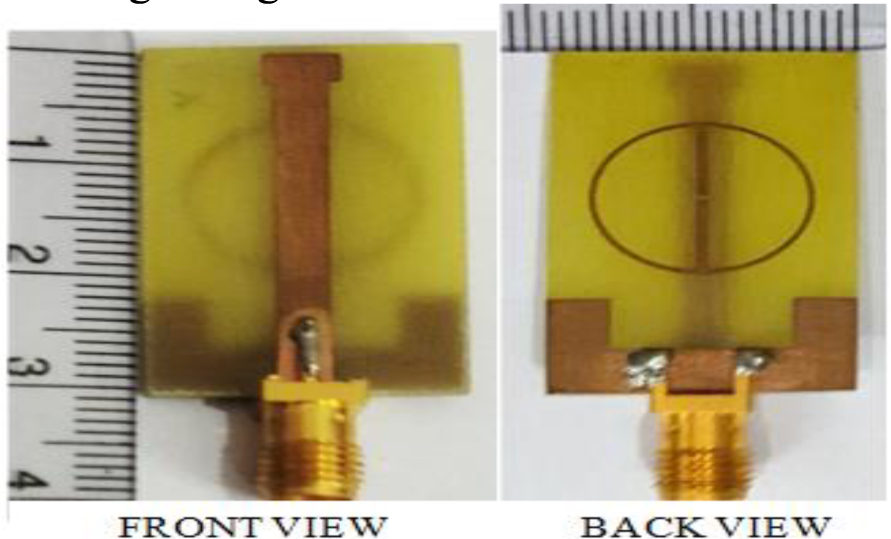
Figure 5: Photograph of the fabricated antenna.
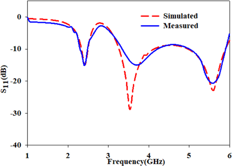
Figure 6: Simulated and measured S of the proposed antenna.
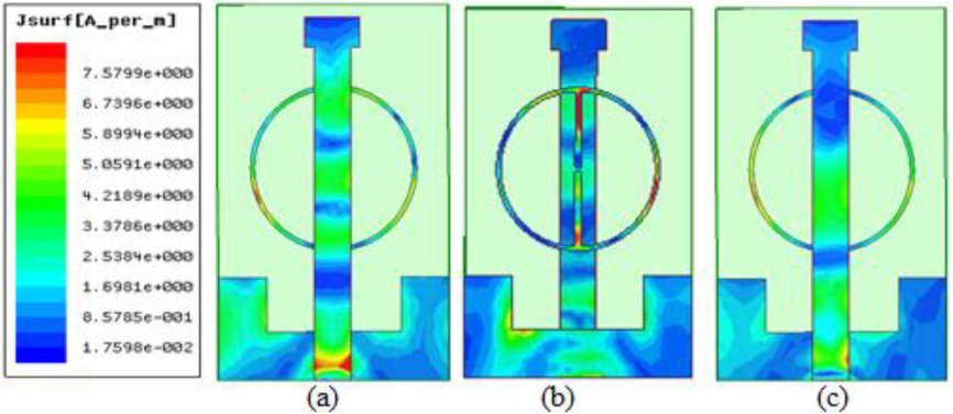
Figure 7: Surface current distributions at (a) 2.4 GHz, (b) 3.5 GHz, and (c) 5.5 GHz.
5 RESULTS AND DISCUSSIONS
As per the values proposed in Table 1, a prototype has been fabricated and tested. The photograph of the fabricated antenna is shown in Fig. 5. A comparative study of the proposed antenna with the existing antennas shows that the proposed metamaterial-loaded compact multi-band monopole antenna is more compact than the other existing schemes used for miniaturization.
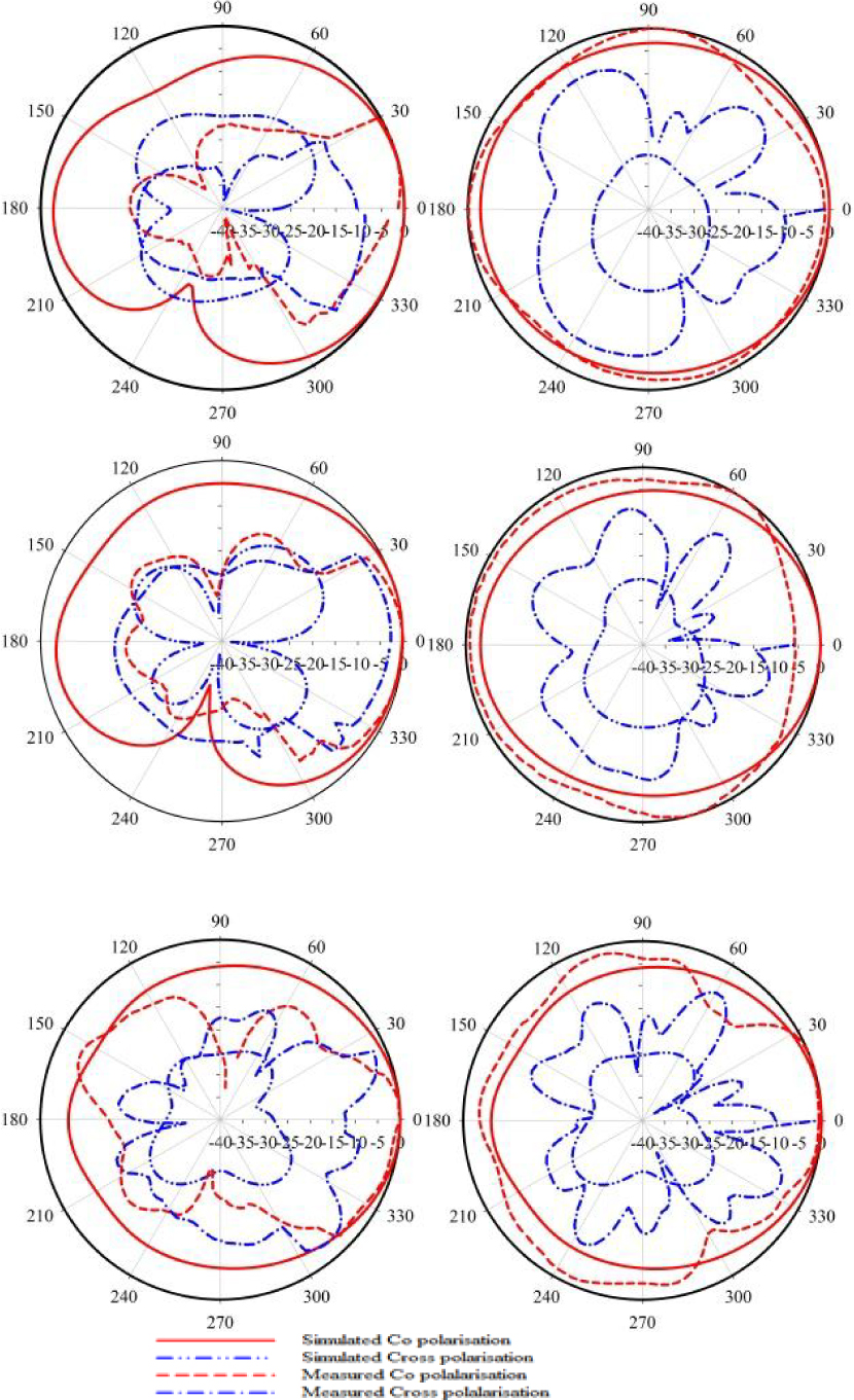
Figure 8: Measured radiation patterns of the antenna at Y-Z and X-Z planes (a) 2.4 GHz, (b) 3.5 GHz, and (c) 5.5 GHz.
The simulated and measured Sare plotted in Fig. 6. The (-10) dB impedance bandwidths at three operating bands 2.4 GHz, 3.5 GHz, and 5.5 GHz are 200 MHz, 800 MHz, and 900 MHz respectively, which cover all the bands of WLAN and WiMAX simultaneously. The simulated and measured return loss are in good agreement.
To understand the influence of DNG structure on the monopole antenna, simulated current distribution at 2.4 GHz, 3.5 GHz, and 5.5 GHz frequencies are illustrated in Fig. 7. This illustrates that at 2.4 GHz and 5.5 GHz the monopole along with DNG jointly creates the resonance. At 3.5 GHz most of the current is in DNG alone, and it shows that the DNG structure generates the additional resonance.
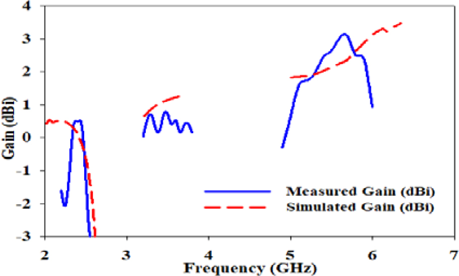
Figure 9: Measured and simulated gain across operating bands for the proposed antenna.
Figure 8 shows the normalized radiation characteristics in the x-z plane and y-z plane at 2.4 GHz, 3.5 GHz, and 5.5 GHz of the proposed antenna. The proposed antenna is omnidirectional in the x-z plane and directional in the y-z plane in the desired bands; hence it can be used for portable wireless devices.
The measured and simulated gain in three wireless application bands is plotted in Fig. 9. This figure shows that all the bands have positive gain with a maximum of 3 dBi gain at 5.5 GHz A monopole antenna with a DNG structure gives improved gain characteristics than a simple monopole without DNG having comparable dimensions. This happens because the DNG eliminates substrate surface waves and the radiated energy is concentrated.
6 CONCLUSION
An MTM-loaded compact multi-band monopole antenna for WLAN/WiMAX applications is proposed. The measured results of the antenna show good impedance bandwidth of 6.25%, 24.57%, and 16.54% for the three bands centered at 2.4, 3.5, and 5.5 GHz Measured and simulated radiation characteristics show good agreement. The proposed MTM structure is simple in design with double negative capability. The novelty of the proposed antenna is that a simple DNG structure is used and the monopole antenna loaded with the DNG results in miniaturization and an additional operating band. MTM loading enables the antenna to achieve a compact electrical size of at 2.4 GHz with improved radiation characteristics. Dependencies of resonant frequencies on various parameters are formulated. The full-wave simulation and design equation of the three resonances show a negligible difference. The proposed multiband antenna has the advantage of compact size, easiness of fabrication, and finds applications in wireless portable devices.
REFERENCES
[1] W. C. Liu, C. M. Wu, and Y. Dai, “Design of triple frequency microstrip-fed monopole antenna using defected ground structure,” IEEE Transactions on Antennas and Propagation, vol. 59, no. 7, pp. 2457-2463, 2011.
[2] M. Kumar and V. Nath, “Analysis of low mutual coupling compact multi-band microstrip patch antenna and its array using defected ground structure,” Eng. Sci. Technol, vol. 19, no. 2, pp. 866-874, 2016.
[3] W. Hu, Y. Z. Yin, P. Fei, and X. Yang, “Compact triband square-slot antenna with symmetrical L-strips for WLAN/WiMAX applications,” IEEE Antennas and Wireless Propagation Letters, vol. 10, pp. 462-465, 2011.
[4] L. Dang, Z. Y. Lei, Y. J. Xie, G. L. Ning, and J. Fan, “A compact microstrip slot triple-band antenna for WLAN/WiMAX applications,” IEEE Antennas and Wireless Propagation Letters, vol. 9, pp. 1178-1181, 2010.
[5] A. K. Gautam, L. Kumar, B. K. Kanaujia, and K. Rambabu, “Design of compact F-shaped slot triple-band antenna for WLAN/WiMAX applications,” IEEE Transactions on Antennas and Propagation, vol. 64, no. 3, 2016.
[6] M. Moosazadeh and S. Kharkovsky, “Compact and small planar monopole antenna with symmetrical L- and U-shaped slots for WLAN/WiMAX applications,” IEEE Antennas and Wireless Propagation Letters, vol. 13, pp. 388-391, 2014.
[7] C. V. Anil Kumar, B. Paul, and P. Mohanan, “Compact triband dual F-shaped antenna for DCS/WiMAX/WLAN applications,” Progress in Electromagnetics Research Letters, vol. 78, pp. 97-104, 2018.
[8] V. Deepu, K. R. Raj, M. Joseph, M. N. Suma, and P. Mohanan, Senior Member, IEEE, “Compact asymmetric coplanar strip fed monopole antenna for multiband applications,” IEEE Transactions on Antennas and Propagation, vol. 55,no. 8, 2007.
[9] P. Surendrakumar and B. Chandra Mohan, “A triple-frequency, vertex-fed antenna for WLAN/WiMAX applications [antenna applications corner],” IEEE Antennas and Propagation Magazine, vol. 60, no. 3, pp. 101-106, 2018.
[10] P. Liu, Y. Zou, B. Xie, X. Liu, and B. Sun, “Compact CPW-fed tri-band printed antenna with meandering split-ring slot for wlan/wimax applications,” IEEE Antennas and Wireless Propagation Letters, vol. 11, pp. 1242-1244, 2012.
[11] Y. Xu, Y. Jiao, and Y. Luan, “Compact CPW-fed printed monopole antenna with triple-band characteristics for WLAN/WiMAX applications,” Electronics Letters, vol. 48, no. 24, pp. 1519-1520, 2012.
[12] R. Mishra, R. Dandotiya, A. Kapoor, and P. Kumar, “Compact high gain multiband antenna based on split ring resonator and inverted f slots for 5g industry applications,” Applied Computational Electromagnetics (ACES) Journal, vol. 36, no. 8, 2021.
[13] L. Peng, C. Ruan, and X. Wu, “Design and operation of dual/triple-band asymmetric M-shaped microstrip patch antennas,” IEEE Antennas and Wireless Propagation Letters, vol. 9, pp. 1069-1072, 2010.
[14] X. Teng, X. Zhang, Y. Li, Z. Yang, D. Liu, and Q. Dai, “A compact triple-band printed monopole antenna for WLAN/WiMAX applications,” ISAPE2012, Xian, pp. 140-143, 2012.
[15] A. Kumar and A. P. S. Pharwaha, “Triple band fractal antenna for radio navigation and fixed satellite services using dragonfly optimization,” Adv. Electromagnetics, vol. 8, pp. 43-49, 2019.
[16] H. Huang, Y. Liu, S. Zhang, and S. Gong, “Multi-band metamaterial loaded monopole antenna for WLAN/WiMAX applications,” IEEE Antennas and Wireless Propagation Letters, vol. 14, pp. 662-665, 2015.
[17] R. S. Daniel, R. Pandeeswari, and S. Raghavan, “A compact metamaterial loaded monopole antenna with offset-fed microstrip line for wireless applications,” International Journal of Electronics and Communications, vol. 83, pp. 88-94, 2017.
[18] T. Ali, M. M. Khaleeq, S. Pathan, and R. C. Biradar, “A multiband antenna loaded with metamaterial and slots for GPS/WLAN/WiMAX applications.” Microwave Optical Technology Letters, vol. 60, pp. 79-85, 2017.
[19] P. Liu, Y. Zou, B. Xie, X. Liu, and B. Sun, “Compact CPW-fed tri-band printed antenna with meandering split-ring slot for WLAN/WiMAX applications,” IEEE Antennas and Wireless Propagation Letters, vol. 11, pp. 1242-1245, 2012.
[20] S. K. Sharma, J. D. Mulchandani, D. Gupta, and R. K. Chaudhary, “Triple band metamaterial-inspired antenna using FDTD technique for WLAN/WiMAX applications,” Int J RF Microw Comput Aided Eng., vol. 25, pp. 668-695, 2015.
[21] R. Rajkumar and K. A. Usha Kiran, “Compact metamaterial multiband antenna for WLAN/WiMAX/ITU band applications,” International Journal of Electronics and Communications, vol. 70, no. 5, pp. 599-604, 2016.
[22] A. W. Mohammad and T. A. Ali, “Compact coaxial fed metamaterial antenna for wireless applications,” Journal of Instrumentation, vol. 14, 2019.
[23] C. Zhu, T. Li, K. Li, Z.-J. Su, X. Wang, H.-Q. Zhai, L. Li, and C.-H. Liang, “Electrically small metamaterial-inspired tri-band antenna with meta-mode,” IEEE Antennas and Wireless Propagation Letters, vol. 14, pp. 1738-1741, 2015.
[24] R. Salhi, M. Abidi, and F. Choubani, “A wide band microstrip antenna based on active circular SRRs,” ICWITS / ACES, 2016.
[25] G. Dai, X. Xu, and X. Deng, “Size-reduced equilateral triangular metamaterial patch antenna designed for mobile communications,” Applied Computational Electromagnetics Society (ACES) Journal, vol. 36, no. 8, pp. 1026-1030, 2021.
[26] C. A. Balanis, Antenna Theory Analysis and Design, 3rd ed., John Wiley & Sons, USA, 2005.
[27] X. Chen, T. M. Grzegorcezyk, B. Wu, J. Pacheco, Jr., and J. A. Kong, “Robust method to retrieve the constitutive effective parameters of metamaterials,” Physics Review E, vol. 70, 2004.
[28] A. B. Numan and M. S. Sharawi, “Extraction of material parameters for metamaterials using a full-wave simulator,” IEEE Antennas and Propagation Magazine, vol. 55, pp. 202-211, 2013.
[29] S. Thankachan, B. Paul, A. Pradeep, and R. Moolat, “Design and characterisation of simple planar metamaterial structure with double negative properties,” TENCON 2019, pp. 1231-1235, 2019.
BIOGRAPHIES

Shiney Thankachan was born in Kerala, India in 1979. She received her B-Tech and M-Tech degrees from Cochin University of Science and Technology, Cochin, India in 2001 and 2010 respectively. She is currently a research scholar at the School of Engineering, CUSAT, Cochin. Her interests include Metamaterials, Planar antennas, and computational electromagnetics.

Binu Paul was born in Kerala, India in 1971. She received her M-Tech and Ph.D. degrees from Cochin University of Science and Technology, Cochin, India in 1996 and 2006 respectively. She is currently an Associate Professor at the School of Engineering, CUSAT, Cochin. Her research interests include planar antennas, computational electromagnetics, and compact planar filters. She is a member of IEEE Antennas & Propagation Society and IEEE-WIE.

Anju Pradeep was born in Kerala, India in 1972. She received her M-Tech and Ph.D. degrees from Cochin University of Science and Technology, Cochin, India in 2008 and 2015 respectively. She is currently a Professor at the School of Engineering, CUSAT, Cochin. Her research interests include metamaterials and optimization techniques for electromagnetics. She is a member of IEEE Antennas & Propagation Society and IEEE-WIE.

Pezholil Mohanan was born in India on May 30th, 1956. He received his Ph.D. degree in Microwave antennas from Cochin University of Science & Technology in 1985. From 1980 until 1986, he worked as a Lecturer in Physics at St. Albert’s College, Cochin. He spent two years in Bharat Electronics (BEL), Ghaziabad as an Engineer in Antenna R&D Laboratory. Since 1989, he has been working as a faculty of the Department of Electronics, CUSAT, and is presently working as a Professor in the department. His current areas of research activities are microstrip antennas, fdtd analysis, dielectric resonator antennas, superconducting microwave antennas, leaky wave antennas, reduction of radar cross section, and microwave instrumentation, among others. He is a member of IEEE Antennas & Propagation Society and IEEE Microwave & Theory and Techniques Society.

Remsha M received an M.Sc degree in Electronics Science from Cochin University of Science and Technology, Cochin, India, in 2013 and is currently working toward a Ph.D. degree in Microwave Engineering at Cochin University of Science and Technology. Her main research interests include microwave sensors for material characterization, microwave measurement techniques, Stepped Impedance resonators, Antennas, and Substrate integrated waveguides.
ACES JOURNAL, Vol. 37, No. 7, 750–756.
doi: 10.13052/2022.ACES.J.370701
© 2022 River Publishers