Fractal Sectoral Monopole Antenna for UWB Band Applications
A. H. Majeed1 and K. H. Sayidmarie2
1Department of Information and Communication Engineering, College of Information EngineeringAl-Nahrain University, Baghdad, Iraq
asmaahameed37@yahoo.co.uk
2College of Electronic Engineering, Ninevah University, Mosul, Iraq
kh.sayidmarie@uoninevah.ed.iq
Submitted On: June 12, 2021; Accepted On: June 20, 2022
Abstract
This paper proposes a fractal monopole antenna based on a sectoral-shaped patch. To improve the gain of the proposed antenna over a larger bandwidth, the matching was enhanced by attaching two rectangular stubs to the feeding line. The antenna, which is built on an FR4 epoxy substrate with =4.3 and a loss tangent of 0.018 has a compact size of 28 mm31 mm1.6 mm. The antenna covers the UWB range and extends to about the 22 GHz frequency, as well as offers omnidirectional radiation patterns. The optimized configuration was fabricated and tested. The impedance bandwidth of the proposed antenna is about 155% with a reflection coefficient better than 10 dB and has a maximum gain of nearly 4 dBi with a relatively stable omnidirectional radiation pattern.
Index Terms: bandwidth extension, fractal antennas, monopole antennas, stubs, UWB.
1 INTRODUCTION
Since the FCC has designated the frequency band (3.1–10.6 GHz) for unlicensed commercial UWB communications in the United States [1], extensive research has gone into the development of UWB antennas. With the development of many communication systems, larger bandwidths are still needed. The microstrip printed antenna can provide such desired features if the problem of the narrow bandwidth is solved. Traditional geometrical shapes such as triangular, circular, and elliptical disc monopoles were used in many proposed designs of the UWB-printed antennas [2–5]. The aim was to use different shapes to obtain enough bandwidth that may be able to go above and beyond the UWB requirement. The dipole type of antenna has also been proposed and investigated aiming to provide UWB properties, where circular, square, triangular, and other shapes for the two arms have been employed [6, 7]. Most of the presented design methods were based on choosing a certain shape followed by some sort of trial and error procedures to obtain enhanced performance. Initial designs are then developed by customizing corners, slots, slits, or parasitic parts to obtain the desired features. One example was a circular disk monopole that was developed by cutting a small sector to form what was called a packman-shaped antenna [8]. Another example was the use of a circular patch with a sawtooth-like circumference for the extension of the bandwidth and size reduction [9]. A rectangular monopole antenna was developed by cutting rectangles and adding strips to improve the bandwidth [10]. The deployment of advanced simulation software packages like CST and HFSS has aided the above search for the desired antenna characteristics. The influence of many of the antenna parameters on the antenna characteristics is explored aiming to achieve an optimized design. However, there exist some more efficient approaches for designing UWB antennas such as the self-complementary geometries [11, 12].
A large impedance bandwidth can be achieved by exploiting the concept of fractal geometry to obtain a multiband performance covering a wider band [13, 14]. Fractal geometry is a type of geometry that uses rules to repeat and scale a specific shape. The repeated shapes produce a multi-resonance operation in which the resonance frequencies are inversely proportional to the sizes [15]. A tree-shaped monopole, created by arranging several squares or triangles, was proposed in [16] for the enhancement of the antenna bandwidth. The concept was further developed in [17] by proposing the flower fractal geometry, which is inspired by the geometry of flowers where the shape of the petal is scaled, rotated, and repeated a few times. The antenna achieved bandwidth exceeding the UWB range. The shape repetition results in a multi resonance that leads to a wide bandwidth as compared to the single monopole antennas or the dipole antenna [11, 12]. In [14, 16] the scaling factor can be chosen by the designer to achieve the desired performance. Thus, giving more flexibility as compared to the conventional fractals where the scale factor is fixed as in Sierpinski fractals [13] and Koch fractals [18]. Therefore, the multi-resonance frequencies manifest themselves individually instead of forming a unified band.
This paper proposes a fractal monopole antenna based on a sectoral-shaped patch that is scaled down, rotated then repeated to form a fractal geometry. Two or three iterations can be employed to achieve the required bandwidth. To provide proper matching for higher frequencies, two stubs are attached to each side of the feeding line. Thus, the proposed fractal antenna covered the UWB range and further to the 22 GHz frequency. In section II, the proposed fractal is presented, while section III describes the antenna configuration. In section IV, the parametric investigations are used to improve the matching and expand the bandwidth. Section V explains how to improve matching in the upper half of the operating band. In section VI, the antenna’s fabricated prototype is tested, and in section VII, the achieved antenna characteristics are compared to those of other antennas. The conclusions are listed insection VIII.
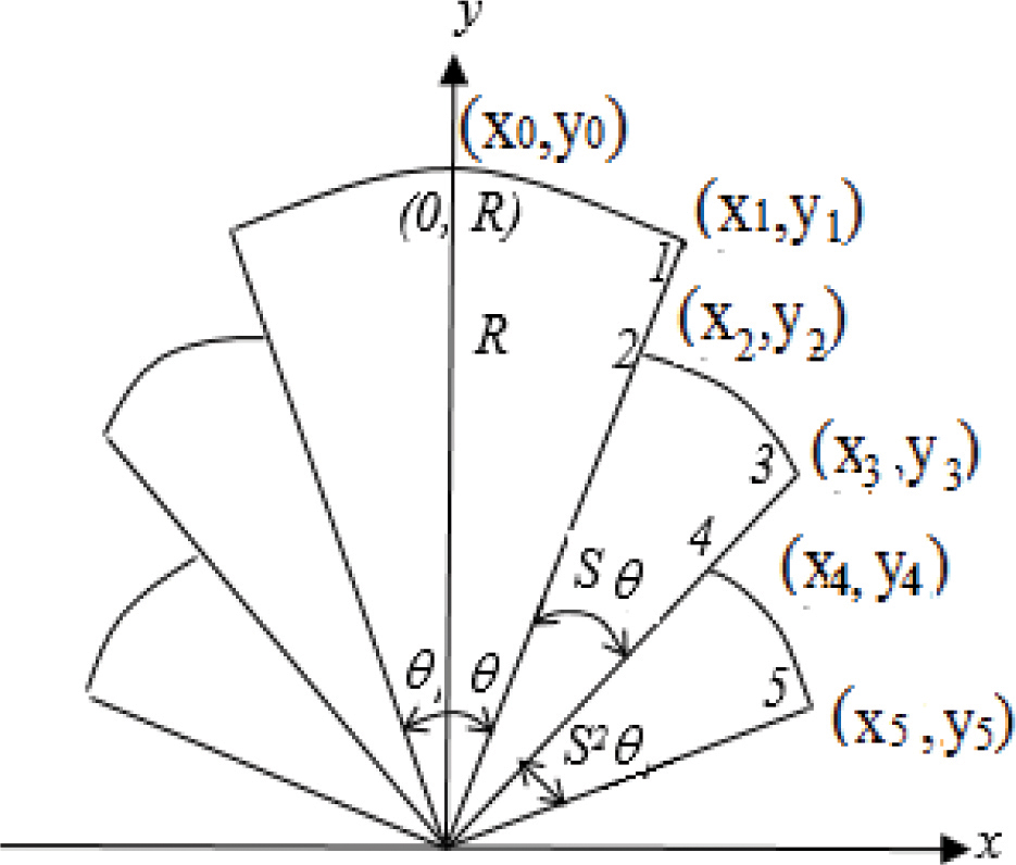
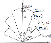
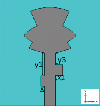
Figure 1: Coordinates of the various corners of the circular sectors for generating the proposed fractal.
2 THE PROPOSED FRACTAL GEOMETRY
The proposed fractal employs the shape of a circular sector, which is iterated by scaling down and repetitions many times as required. The first iteration is represented by two adjacent sectors that are symmetrically placed with respect to the axis of symmetry, as shown in Fig 1. Each of the two sectors is defined by three points; the center of the circle, which is placed at the origin, and two corners points (), (), which are given by:
| (1.a) | ||
| (1.b) | ||
| (2.a) | ||
| (2.b) |
where is the radius of the sector and is the subtended angle, which is measured from the axis of symmetry (Y-axis). The 1 iteration comprises a scaling of the radius and the angle by a factor S, resulting in a new radius of = S, and subtended angle of S. The generated sector is placed adjacent to either of the former ones, with their center at the origin. The corners of the new sector on the right side are given by:
| (3.a) | ||
| (3.b) | ||
| (4.a) | ||
| (4.b) |
Thus, at the nth iteration, the parameters of the sector can be described by:
| (5.a) | |
| (5.b) |
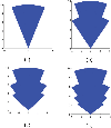
The fractal geometries for the first three iterations were plotted by a MATLAB program, and are shown in Fig. 2.
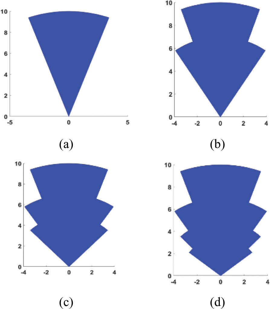
Figure 2: The geometries of the proposed fractal for the iterations; 0, 1, 2, and 3, corresponding to one, two, three, and four sectors.
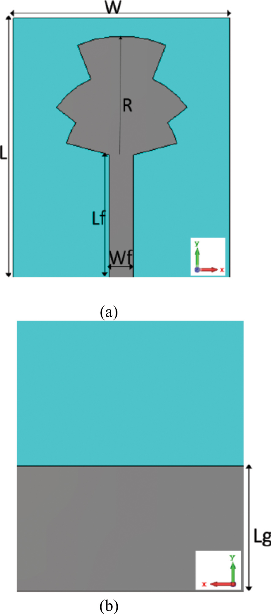
Figure 3: The configuration of Antenna I; (a) Front view, (b) back view.
3 ANTENNA DESIGN
Figure 3 depicts the general configuration of the proposed fractal monopole UWB antenna. The design is based on the 2 iteration of the fractal geometry that is described in section II and shown in Fig. 2 (c). In this design, the scaling factor S is chosen to be smaller than unity, and the total angle is less than 90 so that the radiating patch (monopole) does not overlap the ground plane. The prototype antenna is built on a 28 31 mm FR4 substrate with = 4.3, loss tangent of 0.018, and 1.6 mm thickness. A microstrip feeding line is used to excite the antenna assembly. The length and width of the microstrip lines were determined using the empirical formulas in [19], resulting in a length of 15.5 mm and 3.1 mm width to insure a 50 line impedance.
The Computer Simulation Technology (CST) version 2018, which focuses on a finite integration technique (FIT), is used to study the effect of various parameters on the antenna characteristics, thus optimizing the structure of the proposed fractal monopole form antenna (Antenna-I). We need to describe the surfaces in the CST simulations using equations in terms of R, S, and so that changing the shape in the parametric analysis is much simpler.
The conducting ground plane on the other side of the substrate has a length of Lg=15.2 mm, and thus it covers only a portion of the microstrip feed line. The same metallic material (copper) was used to model the fractal-shaped patch and the ground plane.
4 SIMULATION AND PARAMETRIC ANALYSIS
The impact of various parameters on the response of the proposed Antenna-I is discussed in this section. The following parameters must be optimized:
• The radius Rof the sector,
• The angle l (in radians),
• The scale factor S.
On the other hand, the other parameters of Antenna-I are kept constant. The antenna performance is initially characterized in terms of the reflection coefficient as shown in Figs. 4–6. The following paragraphs address the effects of the sector radius R, scale factor S, and angle on the reflection coefficient response.
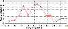
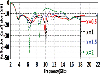
Figure 4 shows the variation of the reflection coefficient with frequency for various patch radii, R, with S= 0.64 and = 0.78 radians. The radius R has a moderate impact on the lower and upper frequencies, as well as on matching, as shown in Fig. 4. It was found that the best patch radius is R=13.9 mm.
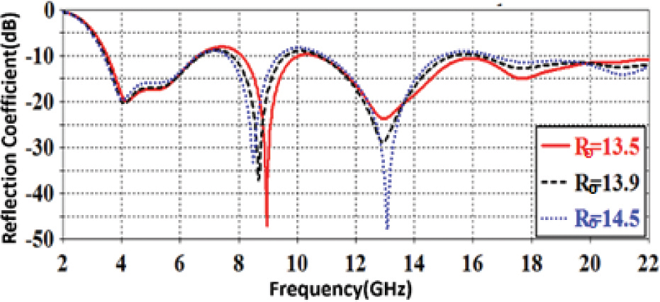
Figure 4: Simulated Antenna-I reflection coefficient as a function of frequency for various patch radii R.
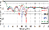
Figure 5 depicts the fluctuation of the reflection coefficient (S) with frequency for different values of the scale factor S with R = 13.9 mm and = 0.78 radians. The scale factor S has a small effect on the lower frequencies, but it has a significant impact on the reflection coefficient at the upper frequencies. With better matching at lower values of S, the upper limit of frequency decreased as S increased. The best scale factor was found to be S = 0.65, which results in a larger bandwidth.
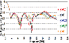
Figure 6 displays the simulated reflection coefficient as a function of frequency for various values of the initial angle . The angle has a minor impact on the lower and upper frequencies, but it improves matching as the angle increases. In terms of reflection coefficient and bandwidth, it was found that the case = 0.8 radians provides a better response. The scale factor was set to 0.65 and radius R was held at 13.9 mm.
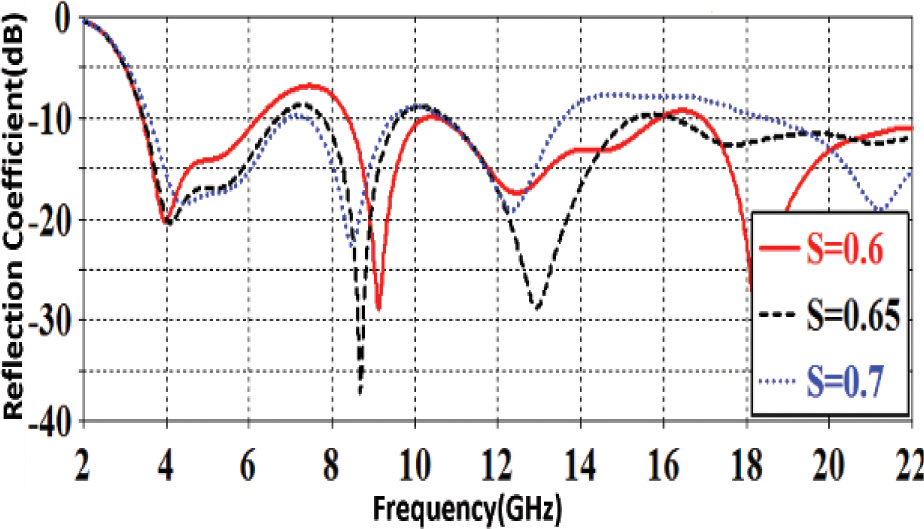
Figure 5: Simulated Antenna-I reflection coefficient as a function of frequency for different scale factors S.
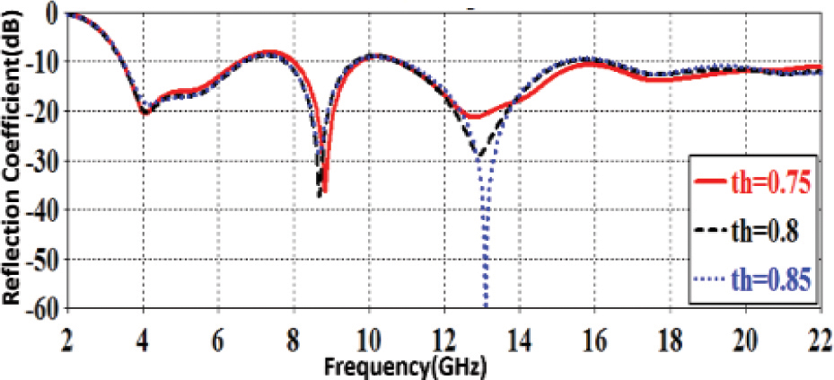
Figure 6: Simulated Antenna-I reflection coefficient as a function of frequency for various angles .
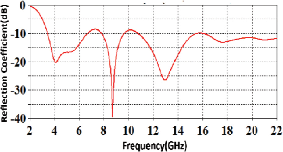
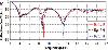
Figure 7. (a): Simulated reflection coefficient for optimized Antenna-I.
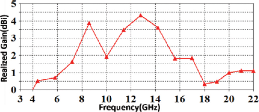
Figure 7. (b): Simulated realized gain for optimized Antenna-I.
Table 1: Optimized parameters of the Antenna-I
| Parameter | Value (mm) | Parameter | Value (mm) |
|---|---|---|---|
| W | 28 | Lg | 15.2 |
| L | 31 | R | 13.9 |
| t | 1.6 | S | 0.65 |
| Lf | 15.5 | 0.8 radian | |
| Wf | 3 |
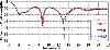
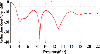
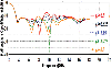
Table 1 shows the optimized parameters for Antenna-I. Figure 7 (a) depicts the optimized Antenna-I simulated reflection coefficient as a function of frequency. This figure shows that Antenna-I has a reflection coefficient 10 dB at 4.09 GHz, 8.7 GHz, 12.9 GHz, 17.6 GHz and 20.9 GHz of 20.3 dB, 36.7 dB, 28.8 dB, 12.7 dB and 12.5 dB respectively. Figure 7 (b) displays the optimized antenna realized gain versus frequency. A maximum gain of 4.62 dBi was achieved in the direction of theta =90 across the band of interest. However, the gain drops at both sides of the operation band.
5 IMPROVED PERFORMANCE
A double-stub matching network was added on each side of the feed line of Antenna-I to produce the developed design Antenna-II, as shown in Fig. 8, aiming to achieve better performance in terms of matching, gain, and impedance bandwidth. The CST program is also used to evaluate and refine the Antenna-II structure to obtain better dimensions of the double-stub matching network, which resulted in improved performance for the Antenna-II.
Figure 9 demonstrates the variation of Antenna-II simulated reflection coefficient versus frequency for various left stub lengths (x). According to practical experience, the stub length should be close to 1/4 the effective wavelength [19], and the optimization of the stub length should begin from there.
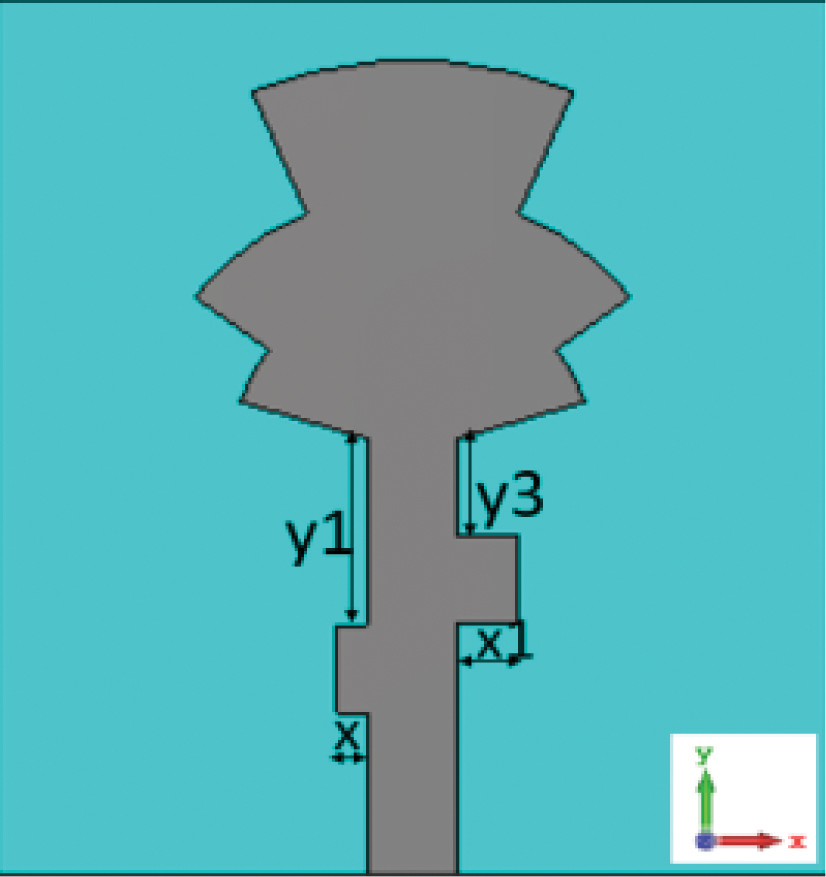
Figure 8: The configuration of the proposed fractal patch monopole antenna (Antenna-II) with the added double-stub network.
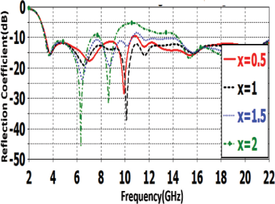
Figure 9: Antenna-II simulated reflection coefficient versus frequency curves with various x.
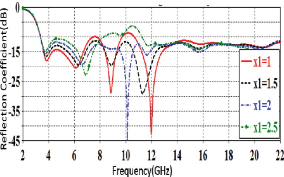
Figure 10: Antenna-II simulated reflection coefficient versus frequency curves for various values of x.
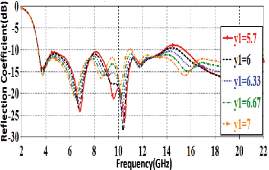
Figure 11: Antenna-II simulated reflection coefficient versus frequency curves for various values of y
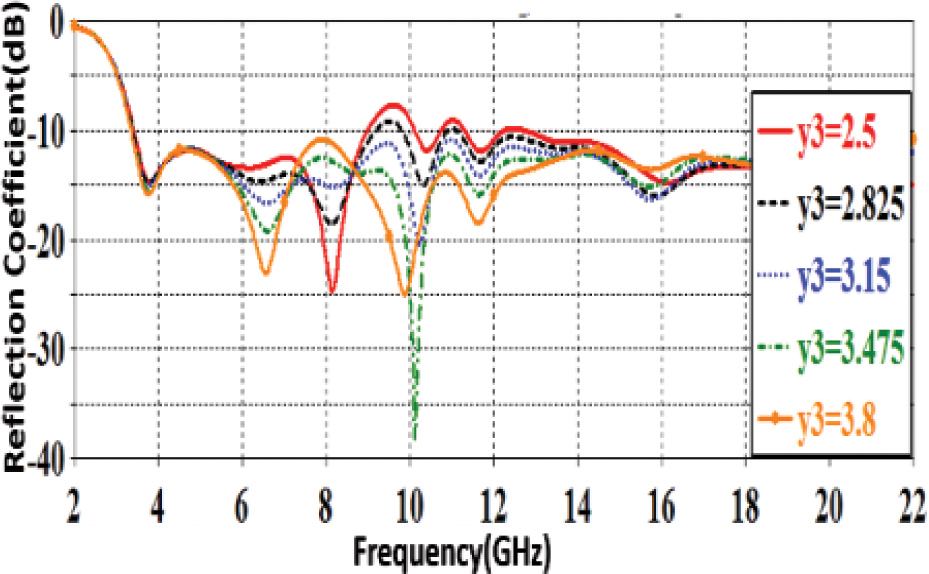
Figure 12: Antenna-II simulated reflection coefficient versus frequency curves with various y.
The variation of the Antenna-II simulated reflection coefficient with frequency for various stub lengths of the right stub (x) is shown in Fig. 10. In terms of matching and impedance bandwidth, it is obvious from this figure that x=2.0 mm provides the best performance.
Figure 11 presents the variation of the Antenna-II simulated reflection coefficient versus frequency for various separations of the left stub from the feeding line upper end (y). It can be seen from this figure that increasing y has no impact on the lower edge of the frequency band but it causes an improvement in the reflection coefficient with the increase in frequency.
The effect of different separations of the right stub (y) from the feeding line upper end of Antenna-II on the reflection coefficient is shown in Fig. 12. It is clear that increasing y has no impact on the frequency band lower edge but it causes an improvement in the reflection coefficient for frequencies greater than 8.5 GHz.
Table 2: Optimized parameters for x, x, y and y of the Antenna-II
| Parameter | Value (mm) | Parameter | Value (mm) |
|---|---|---|---|
| x | 1.25 | x | 2 |
| y | 6.7 | y | 3.47 |
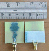
6 ANTENNA FABRICATION AND RESULTS
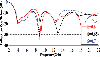
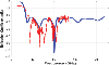
Table 2 lists the optimum parameters for the double stub matching network (x, x, y and y) of Antenna-II, while the other parameters of Antenna-II are left unchanged as they are in Antenna-I. The low-cost antenna is small and simple to fabricate using traditional PCB techniques. The proposed Antenna-II was fabricated as shown in Fig. 13. The antenna was tested by a vector network analyzer (Rode and Schwarz ZVL13) operating up to 13.6 GHz. Figure 14 shows the measured reflection coefficient, compared to the simulation results, where the 10 dB band extends from 3.3 GHz to the upper frequency measurable by the VNA. As a higher frequency analyzer was not available to the authors, the fullly achieved bandwidth cannot be confirmed. It can be seen that the antenna bandwidth extends beyond the UWB, but the simulated results of 20 GHz were not confirmed. Three regions of very low reflection coefficient can be seen around the frequencies; 4.3 GHz, 6.5 GHz, and 10 GHz. These frequencies are proportional to the numbers 0.43: 0.65: 1. These figures are in proportion to S: S:1, i.e., to the fractal scale factor of 0.64 which was used in the design of the antenna (see Table 1). Therefore, the designer can control the multi-resonance frequencies by choosing a proper value for the scale factor.
Figure 15 shows a comparison between Antenna-I and Antenna-II simulated gain versus frequency. It is noted from the figure that the addition of the double stubs improves the gain for frequencies above 16 GHz. The gain response becomes with fewer fluctuations. However, the gain drops from its former values in the frequency range of 10.2 GHz to 15.8 GHz. The use of the two stubs has resulted in reducing the ripples in the gain response.
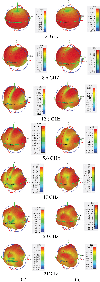
Figure 16 shows the simulated 3-dimensional far-field radiation patterns for Antenna-I and Antenna-II for various frequencies. The two antennas show almost uniform radiation in the horizontal plane, (the plane perpendicular to the antenna), but antenna-II shows better coverage at frequencies above 8.6 GHz. The radiation from Antenna-I exhibits splitting when the frequency is above 9 GHz, but the pattern of Antenna-II keeps its uniformity at frequencies higher than 9 GHz. Thus antenna-II shows better radiation pattern stability with frequency as compared to Antenna-I.
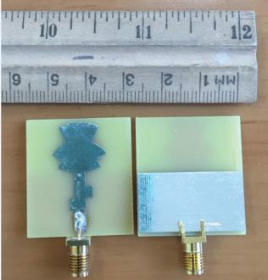
Figure 13: Photographs of the fabricated Antenna-II.
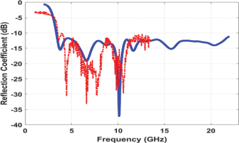
Figure 14: Comparison between Antenna-II simulated (___) and measured (—-) reflection coefficient as a function of frequency.
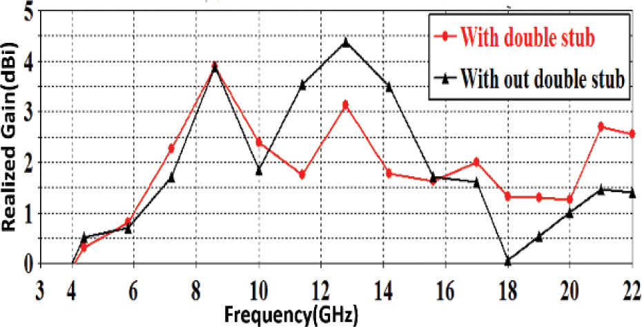
Figure 15: Comparison of Antenna-I and Antenna-II simulated gain as a function of frequency.
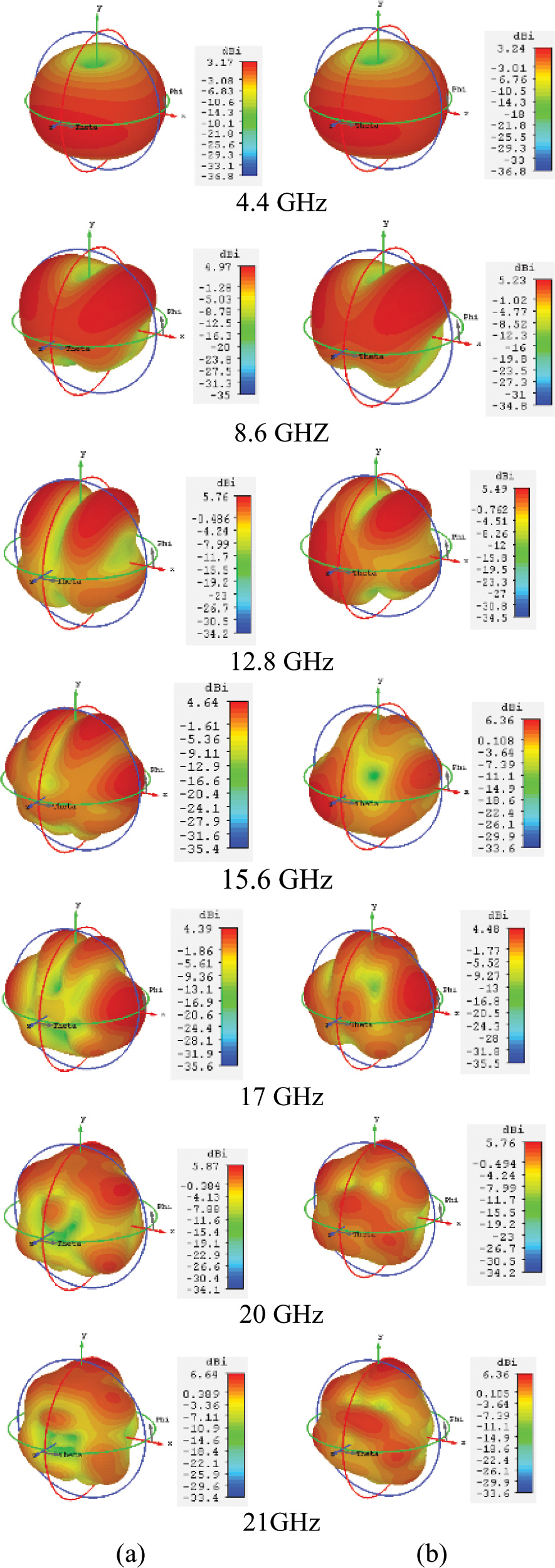
Figure 16: comparison of 3-D far-field radiation patterns of (a) Antenna-I (without double stubs) and (b) Antenna-II (with stubs) for various frequencies.

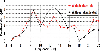
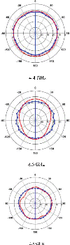
Figure 17: Simulated and measured far-field radiation patterns of the proposed Antenna-II at XZ-plane; simulation (red), Measured (blue) at 4.4 GHz, 8.6 GHz, and 12.8 GHz.
Figure 17 shows a comparison between simulated and measured 1-D radiation patterns of Antenna-II for three frequencies (4.4 GHz, 8.6 GHz, and 12.8 GHz). The patterns were calculated and measured in the plane perpendicular to the antenna. The patterns show the omnidirectional property of the monopole antenna.
7 COMPARISON WITH PREVIOUS WORKS
Table 3 compares the parameters and characteristics of the optimized antenna reported in this paper to those of several UWB antennas disclosed in recent publications. The table shows that the proposed antenna-II achieved the 2 largest bandwidth after that in [11] but at 36% of the size of the antenna in [11]. As regards the size, the proposed antenna has a smaller size than those in [7, 8, 9, 11] and [18]. The proposed antenna has gain values that are comparable to other antennas. The proposed antenna offers a competitive performance of gain, bandwidth, and size.
Table 3: Comparison between recently published UWB antennas and the proposed antenna in this work
| [Ref] | Dimensions [mm] | Frequency range [GHz] | BW [%] | Gain [dB] |
| [4] | 177.61.0 | 4-10.0 | 85.7 | N/A |
| [5] | 25301.6 | 3.6-14.7 | 121.6 | 4 |
| [6] | 40100.8 | 2.8-10.9 | 118 | 2.4-6.2 |
| [7] | 36361.27 | 3.1-11 | 121 | N/A |
| [8] | 25381.6 | 2.9-13 | 127 | 3 9 |
| [9] | 4032.41.5 | 3-11 | 114 | 0 5 |
| [10] | 16201.6 | 4.8 – 13.7 | 96.22 | 2 4 |
| [11] | 52461.6 | 1.8 up to 17.7 | 162 | N/A |
| [15] | 1422 1.6 | 3.05-13.57 | 125 | N/A |
| [18] | 36.2411.52 | 3.05-10.95 | 113 | 1.4-5.7 |
| This work | 2831 1.6 | 3.34 up to 22 | 155 | 0.5-4.0 |
8 CONCLUSION
A compact fractal patch monopole antenna with wide bandwidth and good omnidirectional radiation pattern covering a frequency range beyond the UWB is proposed. A sectoral patch was scaled down and added to the initial one to form the proposed sectoral-shaped fractal. In this way, a design rule has been presented and demonstrated. To improve the proposed antenna gain, two rectangular stubs were attached to the feeding line. The proposed antennas were designed, analyzed, and the optimized design was fabricated. The antenna was able to cover a frequency range of 3.34 GHz up to 22 GHz. The proposed antenna is ideal for UWB applications because of its small size and high impedancebandwidth.
REFERENCES
[1] First Report and Order (FCC 02-48), “New public safety applications and broadband internet access among uses envisioned by FCC authorization of ultra-wideband technology,” Action by the Commission, vol. 14, Feb. 2002.
[2] J. Yeo, Y. Lee, and R. Mittra, “Wideband slot antennas for wireless communications,” IEE Proc. Microwaves Antennas and Propagation, vol. 151, pp. 351-355, 2004.
[3] C. Ying, G. Li, and Y. Zhang, “An LTCC planar ultra-wideband antenna,” Microwave and Optical Technology Letters, vol. 42, pp. 220-222, 2004.
[4] C. Lin, Y. Kan, L. Kuo, and H. Chuang, “A planar triangular monopole antenna for UWB communication,” IEEE Microwave and Wireless Components Letters, vol. 15, no. 10, pp. 624-626, 2005.
[5] A. H. Majeed, K. H. Sayidmarie, F. M. A. Abdussalam, A. Alhaddad, and R. A. Abd-Alhameed, “A. microstrip-fed pentagon patch monopole antenna for ultra-wideband applications,” IEEE Conf. on Internet Technologies and Applications (ITA), pp. 452-456, 2015.
[6] X. N. Low, Z. N. Chen, and T. S. P. See, “A UWB dipole antenna with enhanced impedance and gain performance,” IEEE Transactions on Antennas and Propagation, vol. 57, no. 10, pp. 2959-2966, Oct. 2009.
[7] T. Karakolak and E. Topsakal, “A double-sided rounded bow-tie antenna (dsrba) for UWB communication,” IEEE Antennas and Wireless Propagation Letters, vol. 5, 2006.
[8] S. Naser and N. Dib, “Printed UWB pacman-shaped antenna with two frequency rejection bands,” Applied Computational Electromagnetics Society (ACES) Journal, vol. 32, no. 3, pp. 186-192, Mar. 2017.
[9] A. A. Omar, S. Naser, M. I. Hussein, N. I. Dib, and M. W. Rashad, “Super formula-based compact UWB CPW-fed-patch antenna with and without dual frequency notches,” Applied Computational Electromagnetics Society (ACES) Journal, vol. 32, no. 11, pp. 97-986, Nov. 2017.
[10] M. N. Shakib, M. Moghavvemi, and W. N. L. Mahdi, “Design of a compact planar antenna for ultra-wideband operation,” Applied Computational Electromagnetics Society (ACES) Journal, vol. 30, no. 2, pp. 222-229, Feb. 2015.
[11] K. H. Sayidmarie and Y. A. Fadhel, “Self-complementary circular disk antenna for UWB applications,” Progress in Electromagnetics Research, vol. 24, pp. 111-122, 2011.
[12] K. H. Sayidmarie and Y. A. Fadhel, “A planar self-complementary bow-tie antenna for UWB applications,” Progress in Electromagnetics Research C, vol. 35, pp. 253-267, 2013.
[13] J. Anguera, E. Martinez, C. Puente, C. Borja, and J. Soler, “Broad-band dual-frequency microstrip patch antenna with modified Sierpinski fractal geometry,” IEEE Transactions on Antennas and Propagation, vol. 52, no. 1, pp. 66-73, Jan. 2004.
[14] K. H. Sayidmarie and M. E. Bialkowski, “Fractal unit cells of increased phasing range and low slopes for single-layer microstrip reflectarrays,” IET Microwaves, Antennas & Propagation, vol. 5, no. 11, pp. 1371-1379, 2011.
[15] A. Ghazi, M. N. Azarmanesh, and M. Ojaroudi, “Multi-resonance square monopole antenna for ultra-wideband applications,” Progress in Electromagnetics Research C, vol. 14, pp. 103-113, 2010.
[16] K. H. Sayidmarie and Y. A. Fadhel, “UWB fractal monopoles of rectangular and triangular shapes,” 4th IEEE International Symposium on Microwave, Antenna, Propagation and EMC Technologies for Wireless Communications, pp. 709-712, Nov. 2011.
[17] A. H. Majeed and K. H. Sayidmarie, “Flower shaped elliptical patch antenna for UWB applications,” International Journal of Microwave and Optical Technology, vol. 15, no. 2, pp. 168-178, Mar. 2020.
[18] B. Guenad, A. Chaabane, D. Aissaoui, A. Bouacha, and T. A. Denidni, “Compact cauliflower-shaped antenna for ultra-wideband applications,” Applied Computational Electromagnetics Society (ACES) Journal, vol. 37, no. 1, Jan. 2022.
[19] C. A. Balanis, Handbook of Microstrip Antennas, John Wiley and Sons, New York, 1982.
[20] M. Singh, A. Basu, and S. K. Koul, “Design of aperture coupled fed micro-strip patch antenna for wireless communication,” 2006 Annual IEEE India Conference, pp. 1-5, 2006.
BIOGRAPHIES

Asmaa H. Majeed received B.Sc. Degree in Electronic and Communication from the Department of Electrical Engineering,the University of Technology, Baghdad, Iraq, then an M.Sc degree in Electronic and Communication from the Department of Electrical Engineering, Baghdad University, Baghdad, Iraq. She then received a Ph.D. in Electronic and Communication from the Department of Electrical Engineering/Basrah University, Basrah, Iraq. She has approximately 14 years of teaching experience. She is a member of the teaching staff at the Department of Information and Communication Engineering, College of Information Engineering, Al-Nahrain University, Iraq. She has published 17 papers in national and international journals/conferences. Her research interests include the analysis and design of printed antennas.

Khalil Sayidmarie received a B.Sc. degree with first-class honors in Electronic & Communication Engineering from Mosul University, Iraq, in 1976, and a Ph.D. in Antennas & Propagation from Sheffield University, U.K. in 1981. Then he joined the College of Engineering at Mosul University in 1983 and was promoted to full professor in 1992. He worked as the head of the electrical engineering department for 9 years. He was a co-founder of the College of Electronic Engineering at Mosul University. He has been a professor of communication engineering at that college. Sayidmarie served as a professor of communication engineering at the College of Engineering, University of Amman Al-Ahliyya, Jordan from Oct 2006 to Sept 2009. He is a professor of communication engineering at the College of Electronic Engineering, Ninevah University. He has supervised 45 MSc and Ph.D. theses and published more than 140 papers.
ACES JOURNAL, Vol. 37, No. 8, 912–920.
doi: 10.13052/2022.ACES.J.370810
© 2022 River Publishers