Flat-topped Beams using Phase Compensation based on Low-profile Transmitarray
Hui Zhang, Tianhang Lan, Shan Zhao, Qingqi He, and Zengrui Li
1The State Key Laboratory of Media Convergence and Communication, School of Information and Communication Engineering, Communication University of China, Beijing 100024 China
zhanghuicuc@hotmail.com, cuc_lth09@qq.com, zrli@cuc.edu.cn
2Beijing Institute of Graphic Communication, Beijing 102600, China
zhaoshan@bigc.edu.cn
3School of Electronic Engineering, Guangxi University of Science and Liuzhou 545006, China
qingqih@163.com
Submitted On: September 9, 2022; Accepted On: May 9, 2023
ABSTRACT
This paper proposes a method to add an additional phase compensation to conventional phased arrays to achieve flat-topped beam forming, which can convert the spherical waves emitted by common conical horn antennas into cylindrical flat-topped beams, at the same time, there is also a certain power enhancement. A centrosymmetric unit composed of four layers of F4B and metal patches is designed. By changing the value of the parameters, a 360 phase change can be achieved, and it has the advantages of small size and low-profile. To validate the design concept, a prototype of the transmitarray (TA) was designed, fabricated, and measured by calculating the phase distribution of the front. The measurement results show that the designed TA can achieve flat-topped beams at 5.2GHz, the maximum gain is 1.15dB higher than that of the horn antenna, and the flat-topped range is about 10. The results are in good agreement with the simulation within the test range.
Index Terms: beam forming, flat-topped beams, horn antenna, low-profile, meta-surface, transmitarray.
I. INTRODUCTION
With fifth generation (5G) mobile communication technology developing rapidly, our lives have changed considerably. Beamforming (BF) plays an important role in this because BF can artificially control the direction and shape of the radiation wave to achieve high-efficiency energy propagation and reduce the propagation loss between the transmitting and receiving devices. It is becoming more and more widely applied in wireless communication systems. Commonly used BF target beams include differential beams, cosecant square beams, multi-beams and flat-topped beams. They are often used in surveillance radar systems [1], broadcast and communication satellites [2], radio frequency circuits, wireless charging and drones [3].
Recently, various types of antennas with flat-topped beam radiation patterns have been attracting attention, and the advantage is that their radiated power is completely equal over a wide range of space. If the electromagnetic waves received by the receiving antenna are not uniform in density, the corresponding rectifier circuit design will become very complicated, because the internal diode is highly sensitive to power changes, resulting in a significant reduction in overall reliability and efficiency [4]. For the realization method of the flat-topped beams, many articles have been studied, such as directly feeding different antenna elements in the array to change the amplitude and phase in [5] or by designing a special feed network that is combined with a radiating antenna array [6]. In order to reduce the complexity of feeding the antenna array, planar arrays can be loaded with waveguides to control reactive loads around active radiating elements in the center [7] or sub-array topology optimization [8] to form flat-topped beams. In addition, the methods of synthesizing flat-topped beams using advanced optimization algorithms are also gradually maturing [9-11]. In contrast, antennas using a single feed are more suitable for the energy transmission environment in terms of complexity and practicability. Under the excitation of the microstrip slot antenna, a double-shell dielectric lens antenna [12] and a dielectric resonant antenna [13] based on the principle of combining eigenmodes have achieved good flat-topped performance. Combining the principle of metasurface, [14] designed an ultrathin linear graded index metasurface and a radial graded index metasurface lens, and realized a large-angle flat-topped beam by controlling the microstrip patch antenna. To sum up, although these methods have completed the formation of flat-topped beams, they are more complicated to implement and generally larger in size. We hope to create a simple and fast method for realizing flat-topped beams.
A horn antenna, as a basic element of the antenna system, has the advantages of high gain, wide frequency band, low side lobes, etc. It is very suitable for wireless power transmission, but its maximum power is not flat-topped. TA can change the direction, shape and other characteristics of the received electromagnetic wave by controlling the phase of the elements and radiating it out. It also has the characteristics of no feeding resistance and low cost. Therefore, we aim to transform the spherical wave of the corresponding horn antenna into a flat-topped beam by changing the phase distribution of the TA without weakening the transmission gain of thehorn antenna.
This paper is organized as follows. Section II details the principle of flat-topped BF and proposes a new 360 phase-shift unit for verification. Section III introduces the design of the TA, as well as the simulation and measurement results of the prototype. Section IV concludes the paper.
II. PRINCIPLE ANALYSIS
A. Flat-topped beamforming
In this section, the use of phase divergence for planar transmission arrays to generate flat-topped beams is discussed. The entire antenna system consists of a horn antenna placed along the z-axis with its focus at z=-F and a flat square transmissive array placed along the xoy plane and centered at the origin. Assuming that the electromagnetic waves are radiated from the feed antenna located in the far field and all waves start from the center of the feed, in order to form a pencil beam along the +z direction, the array theory [15] points that a plane composed of NN elements, the phase compensation of the elements (a,b) in row a and column b on the array should be
| (1) |
where k is the wavenumber of free space at the target frequency, p is the side length of each element in the transmission array, R is the relative distances from the center of the element (a,b) on the array to the origin, which can be determined by the following equation
| (2) |
Here, the phase compensation required by the entire unit is approximately replaced by the phase compensation at the center of each unit, and the phase difference caused by the different spacing between the unit and the feed is balanced by assigning different phases to each unit. In this way the spherical waves emitted by the feed antenna can be transformed into plane waves. It can be seen that the phase compensation of the center unit of the array is 0. Besides, as the value R of the unit to the origin increases, the required phase compensation also increases. In order to shape the radiation wave into a flat-topped beam, we add an extra phase ’ to each element, which is also related to the element’s position , and its determination method is
| (3) |
where is a fixed constant, which means that each unit can obtain different divergence degrees according to its own position. Finally, the phase required for each unit is obtained by adding and ’ as
| (4) |
B. Unit cell design and validation
The two basic requirements that the TA unit needs to have are a high transmission coefficient and 360 transmission phase coverage [16–17]. In this part, we propose a basic TA unit shown in Fig. 1, which has a sub-wavelength structure and ultra-thin three-dimensional size, and the overall structure is simple. The cell has a side length of p = 18 mm (about /3 at 5.2GHz), four layers of dielectric substrates are closely stacked, its material is F4B (=2.65 and tan=0.01), and the outer surface of each layer is printed with square metal patches with a side length of s. As phase delay units, the metal patches can achieve 360 phase range by changing the size of its side length. The middle patch layer is a combination of a cross slot and a circular slot. Here, adding a circular slot on the cross slot can increase the transmission coefficient and reduce the reflection loss.
The unit cell was analyzed with the finite element method (FEM) employed by the full-wave simulation software CST Microwave Studio under periodic boundary conditions at sub-6GHz frequencies from 4.8-6 GHz. The incident wave was along the +z direction at normal incidence. Then, the value of s is changed from 2 to 8 mm. The simulation results of the amplitude and phase of the transmission coefficient changing with frequency are shown in Fig. 2. At the target frequency of 5.2 GHz, the amplitude and phase change diagram of the transmission coefficient is shown in Fig. 3 (a). The unit transmission coefficients are all greater than -3 dB, and the phase coverage can reach more than 360.
When the units are arranged in a transmission array, most of the units receive electromagnetic waves that are at an oblique incident angle from the feed horn antenna, so the influence of oblique incidence should also be considered. Figure 3 (b) shows that the change of the incident angle has little effect on the unit performance, which is within an acceptable range.
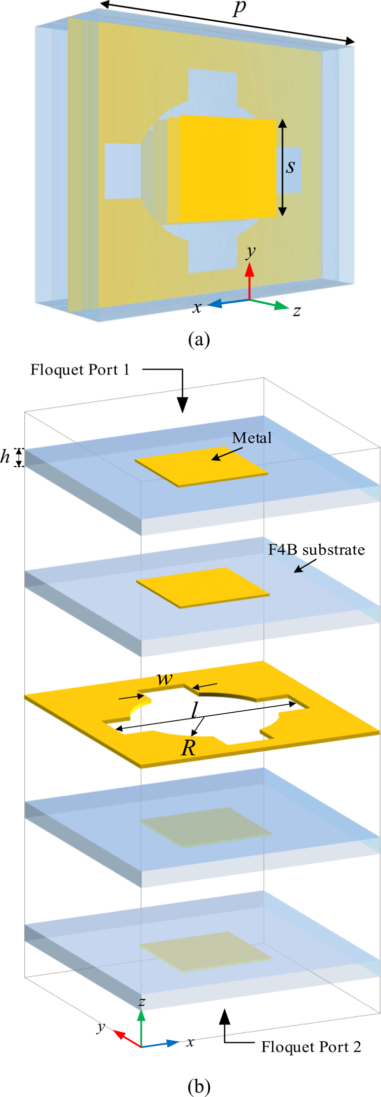
Figure 1: Geometry of unit cell for TA: (a) perspective view and (b) schematic diagram of details. The specific structural parameters are set as h = 1.5mm, w = 4mm, r = 7mm, l = 16mm.
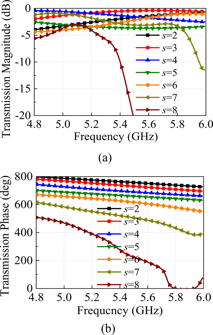
Figure 2: Simulated transmission magnitude and phase of the unit cell under different frequencies: (a) magnitude and (b) phase.
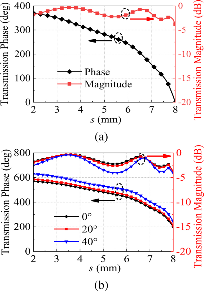
Figure 3: Transmission magnitude and phase against s at 5.2GHz when: (a) vertical incidence and (b) oblique incidence.
C. Array design
In order to achieve flat-topped BF, 1313 elements are selected to form a transmission array in our case, there are 169 elements in total, and its overall size is 234 mm234 mm6 mm (about 4.054.050.1 at 5.2GHz), which is reduced as much as possible while ensuring the performance, and the TA is excited by a linear polarized horn antenna.
Next, it is necessary to determine the position of the feed antenna, that is, to find the appropriate value of F/D. If its value is too large or too small, it will affect the spillover efficiency and illumination efficiency and reduce the efficiency of the antenna system [18]. In addition, if combined with the radiation pattern of the horn antenna when its maximum power drops by 10 dB, the radiation angle deviates from the maximum radiation direction , and F/D=cot()/2 can be obtained. Here, we simulated the gain of the antenna system for different F/D values, and it can be seen from Fig. 4 (a) that the maximum gain is near 0.55. After further simulation, we finally choose the focal length F=125mm, and the corresponding F/D is about 0.53.
Using the theory described in Section II.A, the unit model proposed in Section II.B, and the position of the feed horn that has been determined, the phase of each unit can be calculated by equation (4), and then the phase distribution of the entire array can be obtained. They are plotted in Fig. 4 (b).
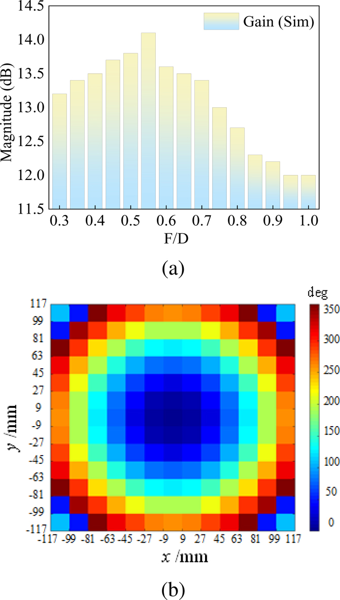
Figure 4: (a) Simulated gain when changing the value of F/D and (b) required phase shift (in degrees) for the flat-topped beam forming when F/D = 0.53.
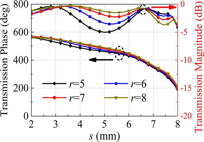
Figure 5: Transmission magnitude and phase against s at 5.2GHz when varying r.
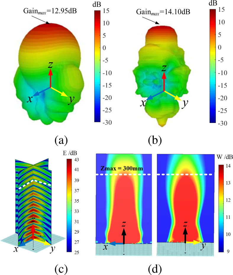
Figure 6: 3-D simulated far-field radiation pattern for (a) feed horn and (b) antenna system. (c) Simulated electric field distribution on xz-plane and yz-plane. (d) Power-flow distribution on xz-plane (left) and yz-plane (right).
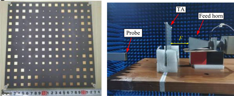
Figure 7: Fabricated TA prototype and measurement setup in the anechoic chamber.
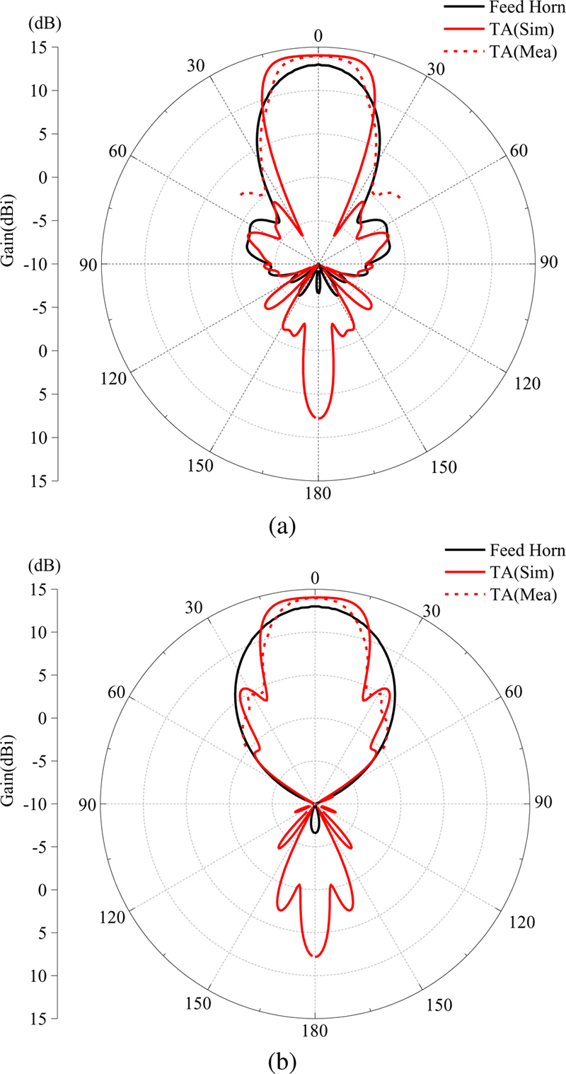
Figure 8: Simulated and measured radiation patterns on (a) xz-plane and (b) yz-plane.
Then, we need to determine the unit cell’s size corresponding to the zero-phase point. When forming an array, in order to minimize the reflection loss, it is necessary to concentrate the cells with good transmission performance in the central part. At the same time, according to the description in [19], on the premise of hardly changing the cell phase, the sidelobe levels can be reduced by adjusting the unit cell’s amplitude. First, according to the amplitude and phase variation diagram shown in Fig. 3 (a), s = 6.7 mm is selected as the phase zero point through calculation. Then we try to adjust the unit amplitude, that is, change the size of r in the unit, and the obtained amplitude and phase vary with s is shown in Fig. 5, and there is only a slight phase change between different units. Ultimately, we chose r = 5 mm elements for the middlemost section, r = 8 mm elements for the surrounding sections, and r = 7 mm elements for the edge sections. In this way, the transmission coefficient of the middle and surrounding parts is less than -1.5dB.
In order to further study the flat-topped beam pattern, the far-field 3D radiation patterns of the simulated horn antenna and the entire antenna system at 5.2 GHz are shown in Figs. 6 (a) and (b). Meanwhile, the electric field distribution on xz-plane and yz-plane are illustrated in Fig. 6 (c). Figure 6 (d) is the power-flow distribution on the corresponding xz- and yz-reference planes, respectively. The results show that after TA, the beam is focused from the original spherical shape to a columnar shape, and the gain is increased by about 1.15 dB. To make it more intuitive, Fig. 6 (c) and Fig. 6 (d) show that in the propagation direction of +z, electromagnetic waves radiate in the form of flat-topped beams, and the maximum transmission distance is about 300 mm (about 5.3at 5.2 GHz). The 2D pattern will be further analyzed in the next section.
D. Fabricated and measured
As shown in Fig. 7, a TA prototype was fabricated using PCB technology. The four-layer plate is fixed by a washer and nylon screws. The TA antenna’s radiation characteristics were performed in an anechoic chamber using the far-field measurement system. The chamber contains a probe and a feed horn. Its placement sequence and overall structure are shown in Fig. 7. The simulated and measured radiation patterns of the flat-topped beam in both principal planes (xz and yz) at 5.2 GHz are shown in Figs. 8 (a) and (b). The simulation and measurement results show good agreement. The incomplete match between them is caused by the measurement and the environment. It can be seen that the beam emitted by the feed horn is focused on the main beam direction after passing through the array, and at the same time, the maximum gain change does not exceed 1% within the range of 10. The maximum gain of the feed horn selected for actual measurement is 12.95 dB, and the maximum gain of the system obtained by simulation and measurement is 14.07 dB and 14.05 dB, respectively. The simulated and measured sidelobe levels are -15.3 dB /-11.97 dB for the xz-plane and -8.37 dB/-9.25 dB for the yz-plane. This difference is related to the radiation pattern of the horn antenna, which can be clearly seen in the Fig. 8.
To illustrate the flat-topped effect, we refer to the shape factor (SF) of the bandpass filter, which is defined here as [3]:
| (5) |
Among it, BWand BW represent the 3 dB gain bandwidth to the 1 dB gain bandwidth of the antenna radiation pattern, respectively. The closer the ratio is to 1, the better the flat-topped effect. For the selected horn antenna, the SFs of the xz-plane and yz-plane are 1.80 and 1.77, respectively. After passing through the antenna array, their sizes are 1.20 and 1.24, respectively, which indicates that the flat-topped beam forming effect is good.
The comparison between this work and previous flat-topped BF research are shown in Table 1. It can be seen from the table that compared with the published designs, this paper uses the form of TA to realize the flat-topped beams while maintaining a high gain, and the TA has the advantages of small size and simple structure.
III. CONCLUSION
In this paper, a new method for flat-topped BF is proposed. The whole antenna system consists of a horn antenna and a TA. By adding an extra phase gradient on the basis of the original phase compensation of the transmission array to change its refractive power, a flat-topped radiation pattern is realized in the direction of the main beam. For verification, a four-layer simple antenna element with 360 phase change is designed. We fabricated and measured a prototype of this antenna array after forming the array using the proposed theory. The experimental results show that at the operating frequency of 5.2 GHz, power enhancement to the corresponding horn antenna and a flat-topped pattern with a wide angle can be achieved. This method has a certain application value in wireless energy transmission. The array as a whole has the characteristics of miniaturization, low profile, simple structure, low cost, center symmetry, and can also be applied to otherTA designs.
ACKNOWLEDGMENT
This work was supported by the National Natural Science Foundation of China (62101515) and the Fundamental Research Funds for the Central Universities.
REFERENCES
[1] H. Chu, P. Li, and Y. Guo, “A beam-shaping feeding network in series configuration for antenna array with cosecant-square pattern and low sidelobes,” IEEE Antennas and Wireless Propagation Letters, vol. 18, no. 4, pp. 742-746, Apr. 2019.
[2] A. Aziz, F. Yang, S. Xu, and M. Li, “A low-profile quad-beam transmitarray,” IEEE Antennas and Wireless Propagation Letters, vol. 19, no. 8, pp. 1340-1344, Aug. 2020.
[3] N. Takabayashi, N. Shinohara, T. Mitani, M. Furukawa, and T. Fujiwara, ”Rectification improvement with flat-topped beams on 2.45-GHz rectenna arrays,” IEEE Transactions on Microwave Theory and Techniques, vol. 68, no. 3, pp. 1151-1163, Mar. 2020.
[4] C. Cheng and K. Huang, “Synthesis of flat-topped beams in wireless power transmission.” Journal of Electronics and Information Technology, vol. 40, no. 5, pp. 1115-1121, May 2018.
[5] A. Li, B. Feng, and L. Deng, “A 45 dual-polarized flat-topped radiation antenna array for 5G applications,” 2021 IEEE 4th International Conference on Electronic Information and Communication Technology (ICEICT), Seoul, Korea, pp. 684-686, Apr. 2021.
[6] L. Sun, “Design of beamforming network with flat-topped radiation patterns,” 2021 IEEE MTT-S International Microwave Workshop Series on Advanced Materials and Processes for RF and THz Applications (IMWS-AMP), pp. 211-213, Nov. 2021.
[7] R. T. Maximidis, A. B. Smolders, G. Toso, and D. Caratelli, “Planar reactively loaded array antenna with flat-top radiation pattern characteristics,” IEEE International Symposium on Antennas and Propagation and North American Radio Science Meeting, Montreal, QC, Canada, pp. 2091-2092, July 2020.
[8] R. Maximidis, D. Caratelli, G. Toso, and A. B. Smolders, “High-gain flat-top antenna sub-arrays for planar arrays with limited field of view,” 14th European Conference on Antennas and Propagation (EuCAP), Copenhagen, Denmark, pp. 1-4, June 2020.
[9] Y. Xu, X. Shi, W. Li, and J. Xu, “Flat-top beampattern synthesis in range and angle domains for frequency diverse array via second-order cone programming,” IEEE Antennas and Wireless Propagation Letters, vol. 15, pp. 1479-1482, Jan. 2016.
[10] P. Angeletti, G. Buttazzoni, G. Toso, and R. Vescovo, “Parametric analysis of flat top beam patterns generated by linear periodic arrays,” 10th European Conference on Antennas and Propagation (EuCAP), Davos, Switzerland, pp. 1-2, Apr. 2016.
[11] S. Khaefi, A. Mallahzadeh, and M. H. Amini, “Flat-topped pattern synthesis of optical leaky-wave antennas.” Optics Communications, vol. 485, p. 126737, Mar. 2021.
[12] N. T. Nguyen, R. Sauleau, and L. Le Coq, “Reduced-size double-shell lens antenna with flat-top radiation pattern for indoor communications at millimeter waves,” IEEE Transactions on Antennas and Propagation, vol. 59, no. 6, pp. 2424-2429, June 2011.
[13] C. K. Wang, B. J. Xiang, S. Y. Zheng, K. W. Leung, W. S. Chan, and Y. A. Liu, “A wireless power transmitter with uniform power transfer coverage,” IEEE Transactions on Industrial Electronics, vol. 68, no. 11, pp. 10709-10717, Nov. 2021.
[14] A. K. Singh, M. P. Abegaonkar, and S. K. Koul, “Wide angle beam steerable high gain flat top beam antenna using graded index metasurface lens,” IEEE Transactions on Antennas and Propagation, vol. 67, no. 10, pp. 6334-6343, Oct. 2019.
[15] A. H. Abdelrahman, F. Yang, A. Z. Elsherbeni, and P. Nayeri, Analysis and Design of Transmitarray Antennas, M&C Publishers, 2017.
[16] J. Tang, X. Chen, X. Meng, Z. Wang, Y. Ren, C. Pan, X. Huang, M. Li, and A. A. Kishk, “Compact antenna test range using very small F/D transmitarray based on amplitude modification and phase modulation,” IEEE Transactions on Instrumentation and Measurement, vol. 71, pp. 1-14, Feb. 2022.
[17] X. Zhang, F. Yang, S. Xu, A. Aziz, and M. Li, “Dual-layer transmitarray antenna with high transmission efficiency,” IEEE Transactions on Antennas and Propagation, vol. 68, no. 8, pp. 6003-6012, Aug. 2020.
[18] M. Jiang, Z. N. Chen, Y. Zhang, W. Hong, and X. Xuan, “Metamaterial-based thin planar lens antenna for spatial beamforming and multibeam massive MIMO,” IEEE Transactions on Antennas and Propagation, vol. 65, no. 2, pp. 464-472, Feb. 2017.
[19] Q. Lou and Z. N. Chen, “Sidelobe suppression of metalens antenna by amplitude and phase controllable metasurfaces,” IEEE Transactions on Antennas and Propagation, vol. 69, no. 10, pp. 6977-6981, Oct. 2021.
BIOGRAPHIES

Hui Zhang received the Ph.D. degree in Communication and Information System from Beijing Jiaotong University, Beijing, China, in 2009. She is currently a Professor with the Communication University of China, Beijing. Her research interests include the areas of finite-difference time-domain (FDTD) methods, electromagnetic scattering, and microstrip antenna arrays.

Tianhang Lann received the B.Eng. degree in Communication Engineering from the Communication University of China, Beijing, China, in 2021. His current research interests include analysis and design of transmitarray antennas.

Shan Zhao received the Ph.D degree from the School of Communication and Information System, Communication University of China, Beijing, China, in 2013. She is currently a lecturer at Beijing Institute of Graphic Communication, China. Her research interests include integral equation and frequency selective surface.

Qingqi He received the bachelor’s degree in Electrical Engineering from Henan Polytechnic University, Jiaozuo, China in 2020. His current research interests include metasurfaces and their antenna applications.

Zengri Lib received the B.S. degree in Communication and Information System from Beijing Jiaotong University, Beijing, China, in 1984, the M.S. degree in Electrical Engineering from the Beijing Broadcast Institute, Beijing, in 1987, and the Ph.D. degree in Electrical Engineering from Beijing Jiaotong University in 2009. He is currently a Professor with the Communication University of China, Beijing. He studied at Yokohama National University, Yokohama, Japan, from 2004 to 2005. His research interests include the areas of finite-difference time-domain (FDTD) methods, electromagnetic scattering, metamaterials, and antennas.
ACES JOURNAL, Vol. 38, No. 6, 409–415
doi: 10.13052/2023.ACES.J.380605
© 2023 River Publishers