An Ultra-small Heated Area Masked Microwave Hyperthermia Therapy Scheme in Fresnel Region
Tamer G. Abouelnaga and Maha R. Abdel-Haleem
1Microstrip Circuits Department, Electronics Research Institute ERI, Cairo, Egypt
Tamer@eri.sci.eg
2Banha Faculty of Engineering, Banha University, Banha, Egypt
Submitted On: September 27, 2022; Accepted On: April 27, 2023
ABSTRACT
This paper introduces a localized masked thermal therapy method for only the breast through the Fresnel region. A pyramidal horn antenna has been used as a hyperthermia system applicator. The antenna is fed by a Yagi array and resonates at 4.74 GHz. A metal plate with a square slot masked the breast phantom. The antenna irradiates the breast phantom for 5 and 10 minutes with input power of 10 and 20 watts (W). Thermal and specific absorption rate (SAR) distributions are studied under the same conditions for a fair comparison between masked and unmasked system performance. The square slot dimensions are altered, and their effects are studied considering the phantom heated area. Moving from unmasked to masked hyperthermia scenarios, a heated area size reduction of 99.87 % is achieved along with a very considerable SAR value reduction. The masked scenario elevates the breast temperature to 43 in a very concentrated area. The proposed system can elevate only an area of of the breast tissue to a temperature of 40 in 5 minutes, and that is a very promising result in hyperthermia therapy applications.
Index Terms: antenna, array, hyperthermia, near-field, SAR.
I. INTRODUCTION
Hyperthermia is a therapeutic procedure used for the treatment of some cases of cancer [1, 2]. To destroy the cancerous cell, the tumor temperature is raised to a higher value than the surrounding normal body tissues. It involves achieving and maintaining temperatures of the order of 42-45C for several minutes at the tumor location. A higher level of water content present in tumor cells increases their conductivity, leading to higher absorption of electromagnetic energy. It has been shown [3, 4] that hyperthermia treatment increases the effectiveness of chemotherapy and radiotherapy. Hyperthermia can be performed on the whole body, or be regional or localized, depending on the size of the tissue region to be heated. In localized hyperthermia, only the local tumor region is heated and is mainly used for the treatment of superficial tumors. Providing uniform heating and not overheating the surrounding healthy tissue region are the two most important challenges associatedwith hyperthermia.
Based on the mechanism used for heating, the hyperthermia applicator’s exposure region can be classified into near- and far-field. In far-field exposure, a directive antenna is used under free space conditions for exposing biological samples [5–7]. Many techniques have been applied to analyze the power density distribution in the sample under test [7]. Far-field exposures have low exposure efficiency (10-15%). For an antenna to achieve high power density, there are two possible ways: Increase the output power [6, 7], or add an extra parameter for enhancing power transfer to the tissue [5]. Hence recent research has moved to near-field exposure which offers better exposure efficiency and results in high power density levels absorbed by the biological sample. A literature review of antenna arrays used for hyperthermia treatment and operating in the near-field region is introduced and summarized in Table 1. The comparison considers the frequency of operation (), the antenna type and area, the distance from the phantom , and the targeted tissue region. In addition, it shows whether any matching medium was used with the applicator or not.
Table 1: Different hyperthermia applicators
| Ref. | [8] | [9] |
|---|---|---|
| 0.915 | 0.433 | |
| Tissue | Arm | Fat |
| Applicator | 8-dipole array | 42 planar array |
| Area | 2222 | 5650 |
| (cm) | 2 | 17.4 |
| Matching med. | Water bolus | Water bolus |
| Results | E-field | SAR |
| Ref. | [10] | [11] |
| 2.45 | 1.8 | |
| Tissue | Breast | Breast |
| Applicator | water-loaded diagonal horns | 16 flexible planar antennas |
| Area | 15150.2 | 2.336 3.921 |
| (cm) | 0 | 0 |
| Matching med. | Water bolus | Customized liquid |
| Results | E-field and SAR | Heat and SAR |
| Ref. | [12] | [15] |
| 4.86 | 2.45 | |
| Tissue | Breast | Breast |
| Applicator | Rectangular grid array | Circular grid array |
| Area | 1517.5 | 170 x 250 |
| (cm) | 6 | 8.7 |
| Matching med. | No | No |
| Results | Heat | SAR and Heat |
In this paper, a masked electromagnetic near-field effect over a human voxel model for different power and exposure time values is described. Human breast phantom is chosen for investigating near-field exposure effects on hyperthermia therapy efficiency. Firstly, the system performance is tested in the applicator’s Fresnel region at a distance with a maximum value of normalized power density. Then, it is masked by of conducting metal sheet. The sheet has a square slot at its center. The square slot dimensions are altered and its effect on the breast phantom heated area is investigated. SAR and thermal results are obtained using the computer simulation technology (CST) simulator under the same condition for a fair comparison. The breast phantom is exposed to the antenna’s electromagnetic wave for 5 and 10 minutes and with different input power (10 W and 20 W) at the applicator input. The suggested system can raise only a patch of breast tissue to a temperature of 40 C in 5 minutes, which is a highly encouraging finding for applications of hyperthermia treatment.
II. HYPERTHERMIA THERAPY IN FRESNEL REGION
In this section, the applicator and its parameters are investigated. The proposed hyperthermia setup with and without the metal mask is presented.
A. Dielectric loaded Yagi fed dual band pyramidal horn applicator
The main goal of designing a hyperthermia applicator is to destroy the cancerous tissue with minimal damage to the healthy cells. A narrow beamwidth and low sidelobe level pyramidal horn antenna at 4.74 GHz based on placing a ten directors Yagi array as an exciter have been introduced in [13]. The dimensions of the rectangular waveguide, with and , as shown in Fig. 1 (a), are given by equation (1) where g is the guided wavelength, and , , and are the medium permeability, permittivity, and speed of thelight respectively.
| (1) |
For air-filled waveguide, operating frequency and cutoff frequency , the waveguide dimensions, , and are found to be 5 cm, 3 cm, and 19.16 cm, respectively, considering the Transverse Electric mode. The pyramidal horn antenna is fed by the Yagi array. The design equations for the pyramidal horn antenna are given by:
| (2) |
The desired antenna gain is assumed to be 15 dB:
| (3) |
| (4) |
The pyramidal horn slant height is determined by:
| (5) |
Antenna sectorial E and H-Plane are provided by:
| (6) |
| (7) |
| (8) |
| (9) |
| (10) |
The calculated and simulated antenna dimensions are given in Table 2.
Table 2: Pyramidal horn antenna dimensions
| Dimension | (cm) | cm) | cm) | (deg) |
|---|---|---|---|---|
| Calculated | ||||
| Simulated |
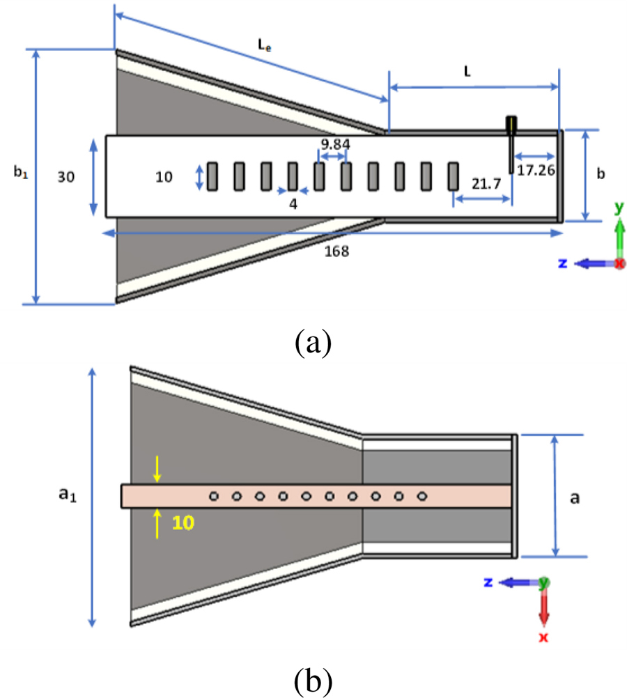
Figure 1: Dielectric loaded pyramidal horn antenna. (a) Side view. (b) Top view.
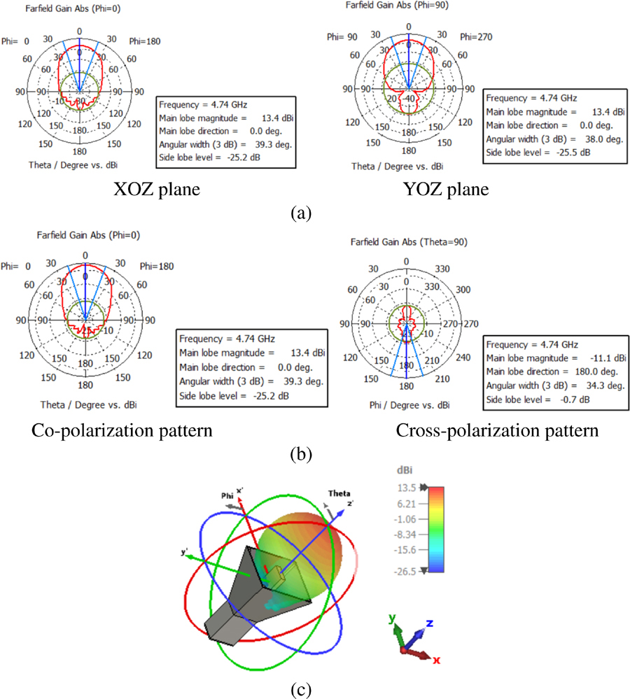
Figure 2: (a) Simulated E-plane and H-plane. (b) Co- and cross-polarization pattern. (c) 3D radiation patterns at 4.74 GHz.
A Teflon rectangular parallelepiped is used as a dielectric material where the Yagi array is placed for horn feeding purposes, as shown in Fig. 1 (a). Directors’ length, position, separation, and number are chosen carefully to obtain a high gain performance. Antenna gain of 13.4 dBi, a side lobe level of 25.4 dB, and a 3 dB beamwidth of 39.3 are obtained at 4.74 GHz, as shown in Fig. 2 (a), for the E-plane. For the H-plane, gain of 13.4 dBi, a side lobe level of 25.6 dB, and a 3 dB beamwidth of 37.9 are obtained at 4.74 GHz. The co- and cross-polarization patterns are shown in Fig. 2 (b). The antenna has a minimum cross-polarization of 16 dB compared to the co-polarization pattern as . The 3D radiation pattern is shown in Fig. 2 (c). The applicator is fabricated and measured for validation purposes. The measured S-parameter agreed with the simulated result with an acceptable discrepancy due to the manual assembly process of the antenna, as shown in Fig. 3. The simulated antenna bandwidth is extended from 3.65 GHz to 5.55 GHz in case of not using the Yagi fed but with a sidelobe level of 13.3 dB at 4.74 GHz. Using the Yagi fed, the sidelobe level becomes 25.6 dB at 4.74 GHz. The simulated bandwidth is extended from 3 GHz to 3.6 GHz, and from 4.6 GHz to 4.87 GHz. The antenna has a very directive beam, low side lobe level, and high-power capability, which make it very good candidate for the proposedhyperthermia application.
The depth of focus, focal plane width, and sidelobe levels are the three most crucial characteristics that may be used to describe a near-field focused (NFF) antenna [14]. The distance between two 3 dB points at the point of maximum power density in a direction normal to the
antenna aperture is known as the depth of focus. The term “focal plane width” refers to the area surrounding the focus point, on a plane perpendicular to the antenna aperture, where the maximum power density is larger than 3 dB on a normalised scale. For optimum hyperthermia therapy performance within the near-field exposure region, the breast phantom should be located at the distance with maximum power density. The normalised power density in the Z direction from the antenna aperture is displayed as shown in Fig. 4 with the antenna in free space. The power density in free space reaches its peak at 20 mm from the antenna aperture. The distance between the two 3 dB points on either side of the greatest power density (the depth of focus) is determined to be 125 mm. A contour map of the power density was created at the greatest power density point at Z=20 mm from the antenna aperture in order to determine the breadth of the focal plane spot region. As shown in Fig. 5, the focal plane’s width in the XY plane is determined to be 60 by 60 mm.
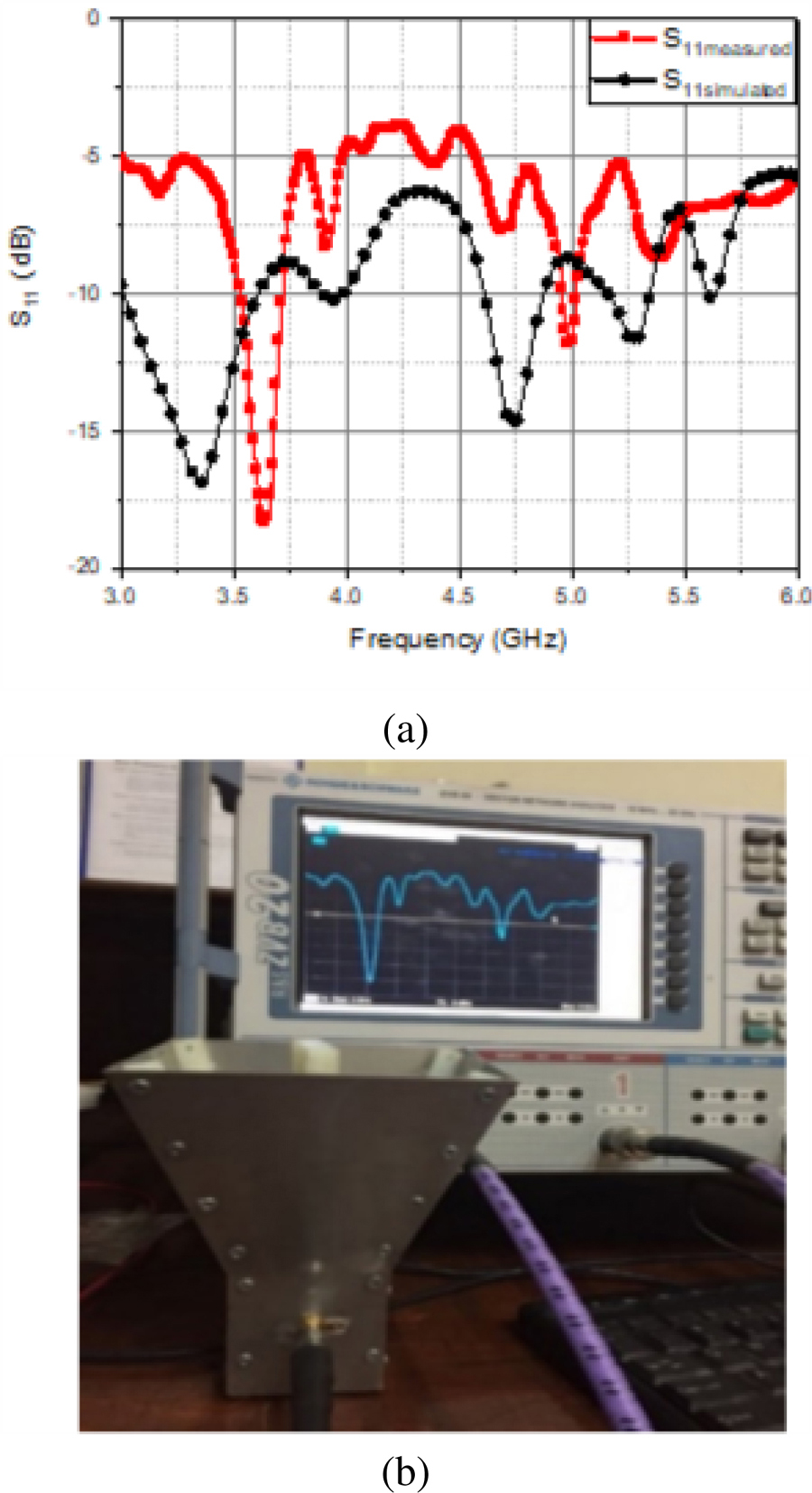
Figure 3: (a) Simulated and measured parameter of the dielectric pyramidal horn antenna. (b) Fabricated dual band dielectric loaded pyramidal horn antenna photo.
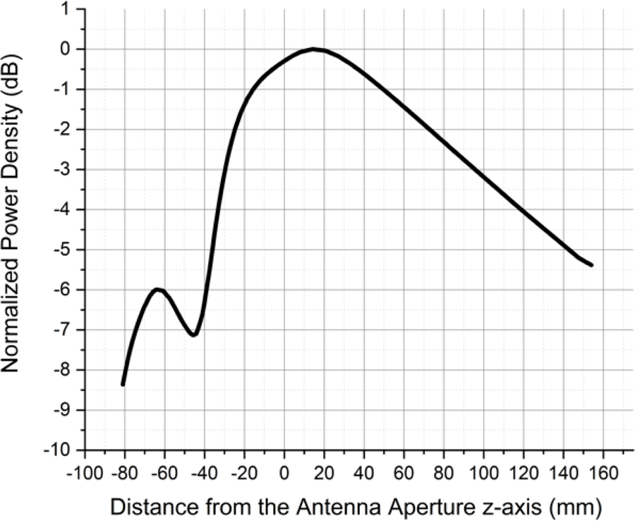
Figure 4: Near-field normalized power density.
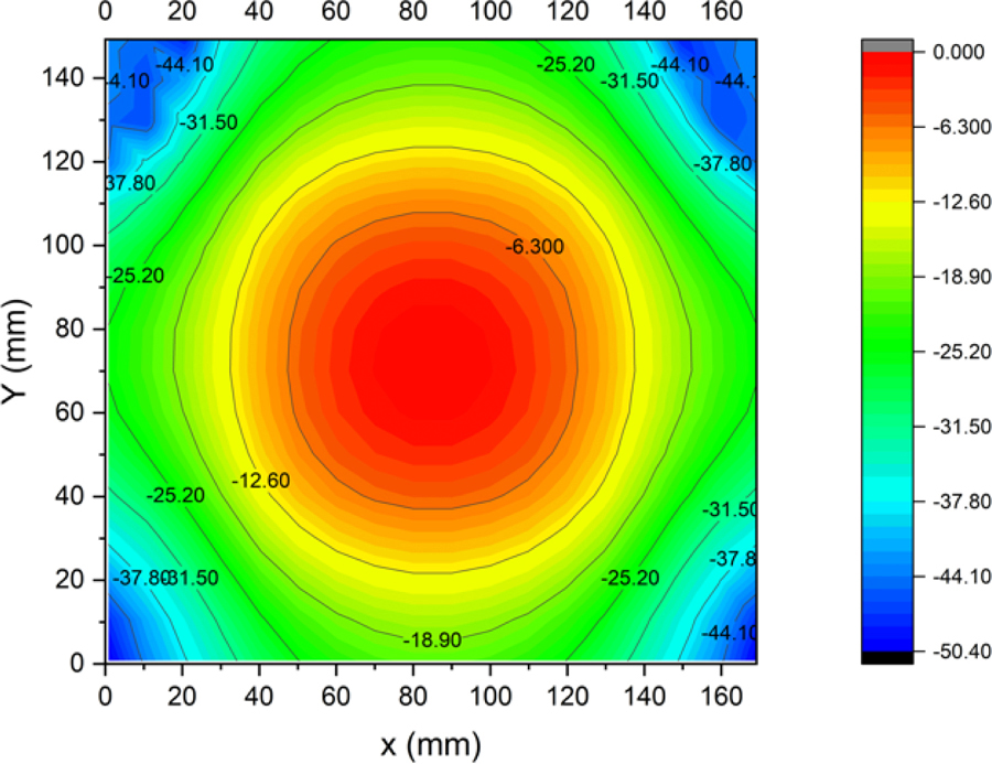
Figure 5: Normalized power density contour at 20 mm from the antenna aperture.
B. Unmasked hyperthermia therapy setup
In medical applications, the width of the focal plane is very important where the electromagnetic energy is mostly concentrated. The tumor region should be located at the focal plane to avoid healthy tissues damage. Depending on normalized power density results, as shown in Fig. 4, the human breast phantom has been located at 20 mm along the z-axis from the antenna aperture. An ambient temperature of 38C is considered. The breast tissue is irradiated for 5 and 10 minutes. Thermal and SAR distribution are studied at an antenna input power of 10 W and 20 W. As shown in Fig. 6, the simulated infected region temperature increases from 38 to 40.38 and 41.3 after an exposure time of 5 minutes and 10 minutes, respectively, with 10 W input power. While at 20 W input power, the temperature reached 43.3 and 45.2 after 5 and 10 minutes, respectively, as illustrated in Fig. 7. SAR values inside the phantom reached 0.868 and 1 W/Kg over 1 g volume for 10 W and 20 W respectively, as shown in Figs. 6 (c) and 7 (c). In contrast, it exceeded the maximum value (1.6 W/Kg averaged over 1 g volume by Federal Communication Commission FCC [16–17]) at limited points at the expense of a small (3 dB) spot area.

Figure 6: Simulated unmasked near field. (a) Heat distribution at 5 minutes. (b) Heat distribution at 10 minutes. (c) SAR at 10 W input power.
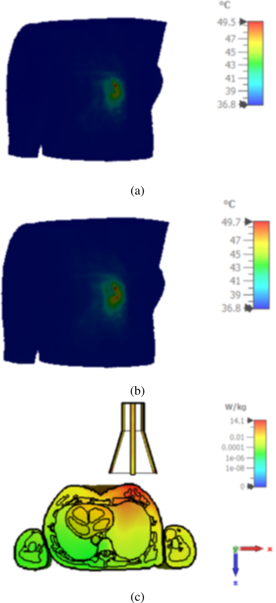
Figure 7: Simulated unmasked near field. (a) Heat distribution at 5 minutes. (b) Heat distribution at 10 minutes. (c) SAR at 20 W input power.
C. Masked hyperthermia therapy setup
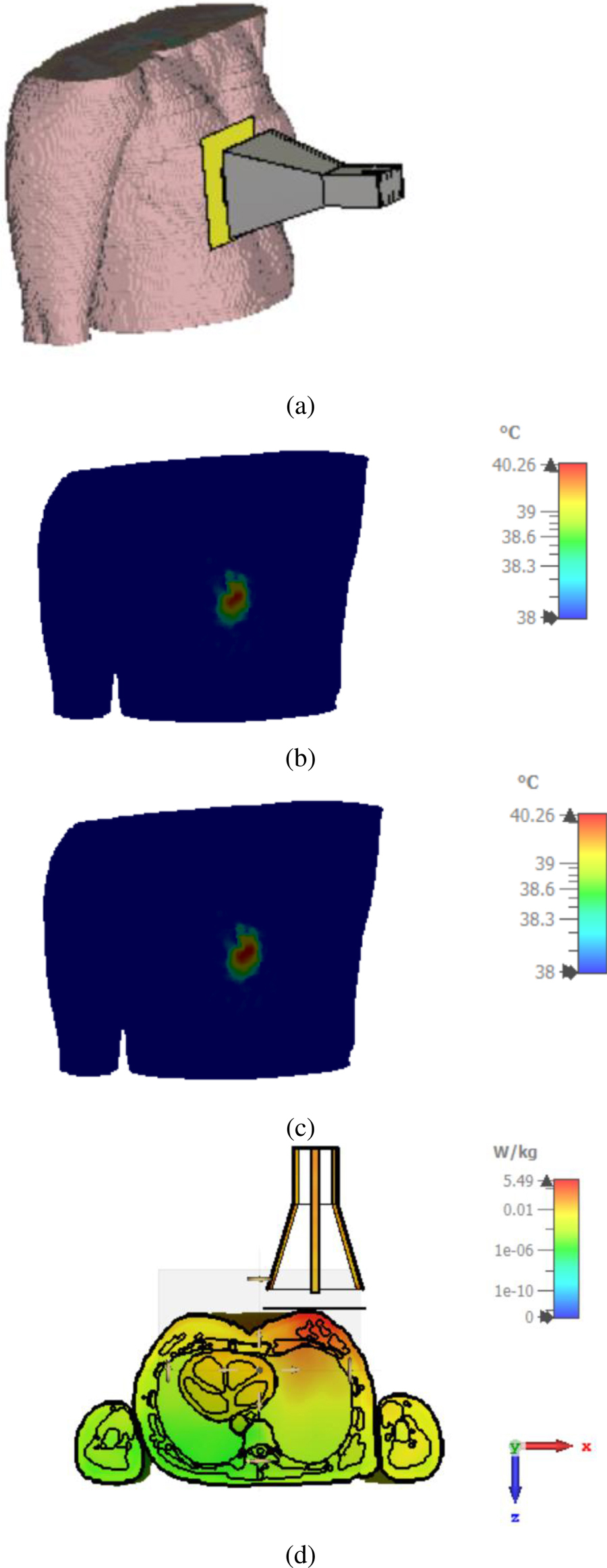
Figure 8: Simulated masked near field. (a) Scheme. (b) Heat distribution at 5 min. (c) Heat distribution at 10 min. (d) SAR at 10 W input power and mask slot dimension of .
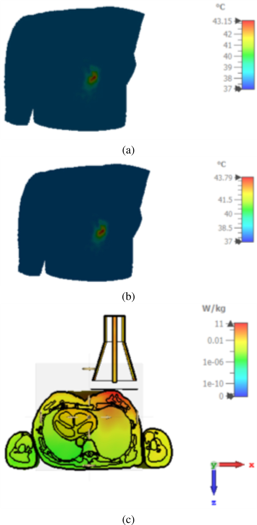
Figure 9: Simulated masked near field. (a) Heat distribution at 5 minutes. (b) Heat distribution at 10 minutes. (c) SAR at 20 W and mask slot dimension of .
Table 3: Slot area effect on masked and unmasked hyperthermia schemes
| Scheme | Power/Time |
Area |
||
| Unmasked | 20 /5 | 50 x 60 | 40 | 49.5 |
| Unmasked | 20 /10 | 53 x73 | 40 | 49.7 |
| Unmasked | 10 /5 | 24 x 38 | 40 | 43.29 |
| Unmasked | 10 /10 | 54 x 36 | 40 | 43.4 |
| Masked | 20 /5 | 27 x 35 | 40 | 43.15 |
| Masked | 20 /10 | 30 x 38 | 40 | 43.79 |
| Masked | 10 /5 | 5 x 12 | 40 | 40.26 |
| Masked | 10 /10 | 16 x 15 | 40 | 40.26 |
| Masked | 20 / 5 | 15 x 12 | 40 | 43.78 |
| Masked | 20 /10 | 15 x 21 | 40 | 44.07 |
| Masked | 20 / 5 | 2 x 2 | 40 | 40.81 |
| Masked | 20 /10 | 4 x 3 | 40 | 40.87 |
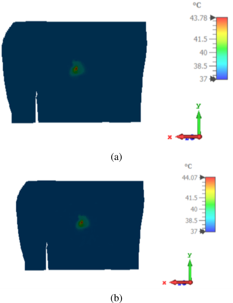
Figure 10: Simulated masked near field. (a) Heat distribution at 5 min. (b) Heat distribution at 10 min at 20 W and mask slot dimension of 2.
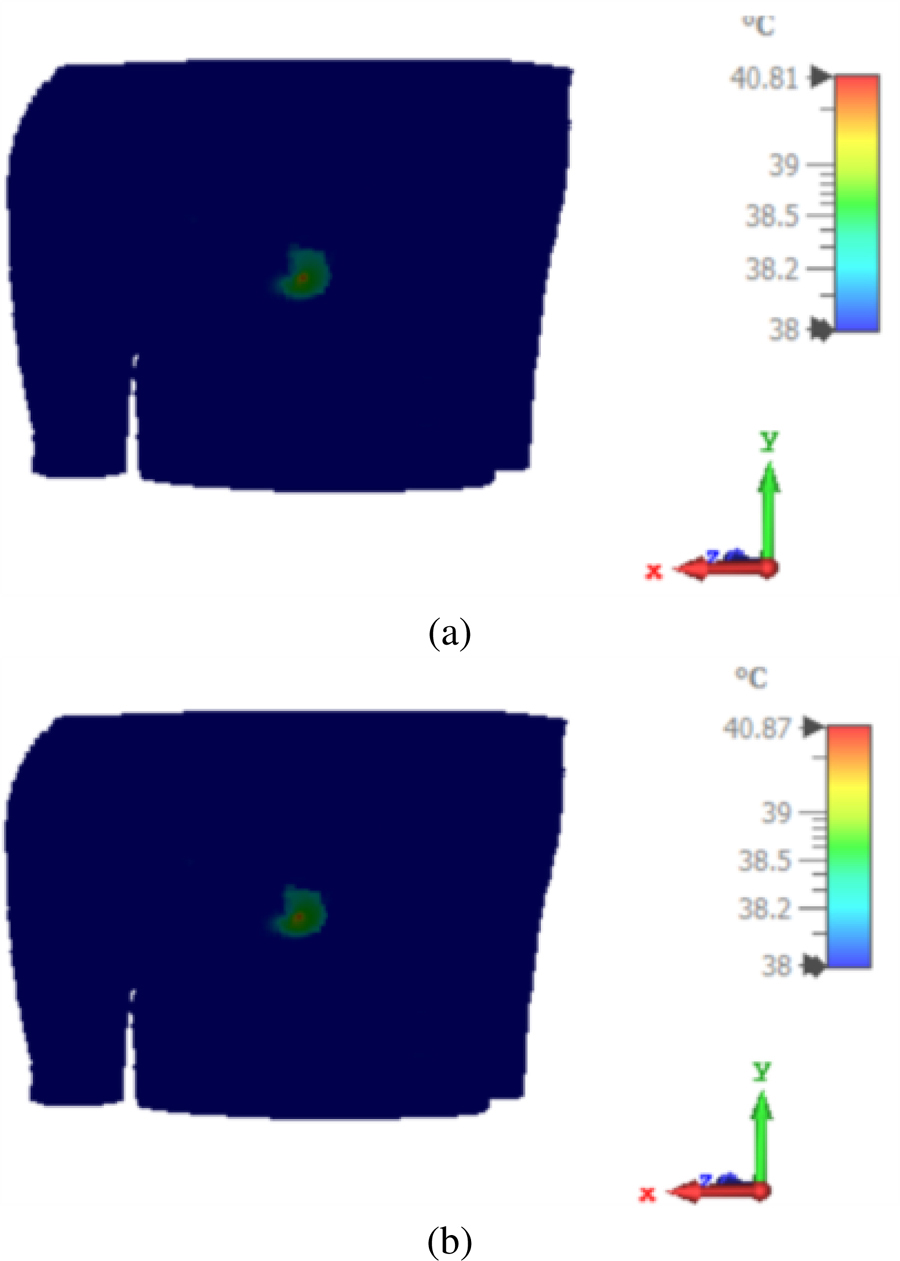
Figure 11: Simulated masked near field. (a) Heat distribution at 5 min. (b) Heat distribution at 10 min at 20 W and mask slot dimension of .
In this section, the width of the focal plane that is irradiated in the infected region of the breast is controlled by a centered slotted metal sheet with dimensions of . The square slot is aligned with the tumor-infected area, as shown in Fig. 8 (a). The metal sheet is 20 mm from the antenna aperture and is in contact with the breast. The square slot dimensions are altered and its effect on the breast phantom heated area is given in Table 3.
Figures 8–10 show the effect of input power and exposure time on the temperature of the infected breast area considering the masked scenario. The heated area is calculated considering a reference temperature of 40 . Considering the unmasked scenario, the heated area is 50 60 . That area is reduced to 27 35 , 15 12 , and 2 2 considering the masked scenario and slot dimensions of , , and , respectively. Input power of 20 W and exposure time of 5 min is considered in both masked and unmasked scenarios. A heated area size reduction of 99.87 % is obtained considering the masked scenario with a slot area of . As the exposure time increases from 5 to 10 min, the heated area size reduction of 99.69 % is obtained. The highest SAR value decreases from 7.07 W/kg in the unmasked situation to 5.49 W/kg in the masked scenario, and from 14.1 W/kg in the unmasked scenario to 11 W/kg in the masked scenario when input power is 10 W and 20 W, respectively. The veiled situation cannot reach 49 C, however temperatures between 40 C and 43 C are still sufficient for hyperthermia treatment.
III. CONCLUSION
A masked near-field localized thermal therapy method was introduced. A 4.74 GHz pyramidal horn antenna was used as a hyperthermia system applicator. The antenna irradiated a breast phantom for 5 and 10 minutes with input power of 10 and 20 W. Thermal and SAR distributions were investigated. Considering the masked scenario with input power of 20 W and exposure time of 5 min and 10 min, a heated area size reduction of 99.87 % and 99.69 % were obtained, respectively. Moving from an unmasked to a masked scenario, the maximum SAR value was reduced from 7.07 , to 5.49 with input power of 10 W and from 14.1 to 11 , with an input power of 20 W. The masked scenario elevated the temperature to 43 in a very concentrated area and that is very promising in hyperthermia therapy applications.
REFERENCES
[1] B. Uysal, “Hyperthermia and breast cancer: A short review,” Journal of Radiology and Oncology, vol. 1, no. 3, pp. 079-082, Oct. 2017.
[2] N. Nizam-Uddin, W. Alkadri, W. A. Malik, I. Elshafiey, and A. F. Sheta, “Towards wideband hyperthermia treatment system,” Applied Computational Electromagnetics Society (ACES) Journal, vol. 9, no. 32, pp. 769-780, Jan. 2017.
[3] P. Faridi, T. B. Shrestha, M. Pyle, M. T. Basel, S. H. Bossmann, P. Prakash, and B. Natarajan, “Temperature estimation for MR-guided microwave hyperthermia using block-based compressed sensing,” 42nd Annual International Conference of the IEEE Engineering in Medicine & Biology Society (EMBC), Montreal, QC, Canada, pp. 5057-5060, July 2020.
[4] O. Debnath, K. Saito, K. Ito, and M. Uesaka, “Breast cancer treatment by combining microwave hyperthermia and radiation brachytherapy,” International Symposium on Antennas and Propagation (ISAP), Okinawa, Japan, pp. 472-473,Oct. 2016.
[5] H. P. Kok and J. Crezee, “Progress and future directions in hyperthermia treatment planning,” 2017 First IEEE MTT-S International Microwave Bio Conference (IMBIOC), Gothenburg, Sweden, pp. 1-4, May 2017.
[6] M. Abdel-Haleem, T. Abouelnaga, M. Abo-Zahhad, and S. Ahmed, “Enhancing microwave breast cancer hyperthermia therapy efficiency utilizing fat grafting with horn antenna,” International Journal of RF and Microwave Computer-Aided Engineering, vol. 31, no. 6, Apr. 2021.
[7] M. Abdel-Haleem, T. Abouelnaga, M. Abo-Zahhad, and S. Ahmed, “A preclinical system for enhancing the efficiency of microwave breast cancer hyperthermia therapy using dielectric matched layer and convex lenses,” Progress in Electromagnetics Research C, vol. 109, pp. 153-168, Jan. 2021.
[8] P. Nguyen, A. Abbosh, and S. Crozier, “Three-dimensional microwave hyperthermia for breast cancer treatment in a realistic environment using particle swarm optimization,” IEEE Transactions on Biomedical Engineering, vol. 64, no. 6, pp. 1335-1344, June 2017.
[9] E. Lekka, D. Konstantinos, and A. George, “Phased array design for near field focused hyperthermia based on reciprocity theorem,” International Workshop on Antenna Technology: Small Antennas, Innovative Structures, and Applications (IWAT), Athens, Greece, pp. 277-280, Mar. 2017.
[10] H. Xiaoping, W. Geyi, and S. Wang, “Optimal design of focused arrays for microwave-induced hyperthermia,” IET Microwaves, Antenna and Propagation, vol. 9, no. 14, pp. 1605-1611, Nov. 2015.
[11] S. Singh and S. P. Singh, “Investigation on improved water-loaded diagonal horn applicators for hyperthermia,” Journal of Electromagnetic Waves and Applications, vol. 30, no. 14, pp. 1836-1857, Aug. 2016
[12] A. Dadzadi and R. Faraji-Dana, “Breast cancer hemispheric shaped hyperthermia system designed with compact conformal planar antenna array,” IEEE Asia-Pacific Microwave Conference (APMC), Singapore, pp. 1107-1109, Dec. 2019.
[13] M. Tayel, T. Abouelnaga, and A. Elnagar, “Pencil beam grid antenna array for hyperthermia breast cancer treatment system,” Circuits and Systems, vol. 8, no. 5, pp. 122-133, May 2017.
[14] M. Tayel, T. G. Abouelnaga, and A. Elnagar, “Dielectric loaded Yagi fed dual band pyramidal horn antenna for breast hyperthermia treatment,” 5th International Conference on Electrical and Electronic Engineering (ICEEE), Istanbul, Turkey, pp. 323-328, May 2018.
[15] P. Nepa and A. Buffi, “Near-field-focused microwave antennas: Near-field shaping and implementation,” IEEE Antennas and Propagation Magazine, vol. 59, no. 3, pp. 42-53, June 2017.
[16] S. Suseela and P. Wahid, “Breast cancer hyperthermia using a grid array applicator,” Southeast Conference, Raleigh, NC, USA, pp. 1-4,Mar. 2020.
[17] M. Tayel, T. G. Abouelnaga, and A. Desouky, “UWB high gain antenna array for SAR based breast cancer detection system,” 5th IEEE International Conference on Electrical and Electronic Engineering (ICEEE), Istanbul, Turkey, pp. 311-316, 2018.
BIOGRAPHIES

Tamer Gaber Abouelnaga was born in November 1976. He received the B.Sc. (Hons.) degree in Electronics Engineering in 1999 from Menofiya University, Egypt. He gained the M.Sc. and Ph.D. degrees in 2007 and 2012, respectively, in Electronics and Communications from Ain Shams University. From 2012 to 2017 he worked as a Researcher, and since 2018 has been an Associate Professor in the Microstrip Circuits Department, Electronics Research Institute, Egypt. From 2018 to 2022 he was Students Affairs and Environmental Development Vice Dean at the Higher Institute of Engineering and Technology, Kafr Elsheikh City. He is currently Students Affairs Vice Dean at the Faculty of Industry and Energy Technology at New Cairo Technological University. He has published 47 papers, 33 papers in peer-refereed journals, and 14 papers in international conferences regarding antennas, couplers, filters, and dividers for different microwave applications. His current interest is in microwave usage in biological applications.

Maha R. Abdel-Haleem was born in 1989. She received the B.S. degree in Electrical Engineering from Benha University, Egypt, in 2011, and the M.S. degree from the School of Electronics, Communications, and Computer Engineering, Egypt-Japan University of Science and Technology, Alexandria, Egypt, in 2016. She is currently an Assistant Professor in the Faculty of Engineering, Banha University. Her research interests include wave propagation and biomedical engineering.
ACES JOURNAL, Vol. 38, No. 4, 277–285
doi: 10.13052/2023.ACES.J.380407
© 2023 River Publishers