A Novel 44 MIMO Antenna Decoupled by T-Shaped Dummy Antenna with High Robustness for 5G Mobile Devices
Junlin Wang, Xiaomin Chen, Xin Wang, and Min Wei
School of Electronic Information Engineering
Inner Mongolia University, Hohhot, 010021, China
wangjunlin@imu.edu.cn, chenxiaomin_ee@163.com
wangxin219@imu.edu.cn, 18709836689@163.com
Submitted On: October 14, 2022; Accepted On: January 23, 2023
ABSTRACT
It is challenging to design a compact antenna pair with isolation better than 20 db and with robustness to antenna position. In this paper, a T-shaped dummy antenna is adopted to decouple the tightly arranged antenna pair for 5G mobile devices. Working in the 3.8 GHz of N77 band, the proposed antenna pair is with an impedance bandwidth of 280 MHz. Isolation of the proposed antenna pair is enhanced from 13 db to 30 db by adding the T-shaped dummy antenna, and it is with high robustness even though the antenna position is altered. The calculation process of the loading requirement of T-shaped dummy antenna is shown. By duplicating the proposed antenna pair, a 44 MIMO antenna with high isolation is proposed. The measured results show the MIMO antenna with isolation better than 31 db, and the average total efficiency is about 49%, and the Envelope Correlation Coefficient (ECC) is lower than 0.05 in the -6 db pass band. To the best of the authors’ knowledge, compared to most of the reported antenna pairs, the proposed 44 MIMO antenna is with the highest isolation while keeping a compact size.
Index Terms: compact antenna pair, decoupling, 5G, high isolation, T-shaped dummy antenna.
I. INTRODUCTION
Multiple-input multiple-output (MIMO) technology is one of the most promising technologies in upcoming 5G mobile communication. One of the mid-bands of sub-6G, N77 (3.3-4.2 GHz), is a good candidate for 5G mobile devices. Recently, many researchers have focused on the MIMO antenna for 5G mobile devices, such as smartphones and tablets. In [1]-[10], many researchers have proposed MIMO antenna with isolation of about 10 db. However, due to the space limitation of the terminal devices, it is challenging to design a MIMO antenna with high isolation level and low envelope correlation coefficient (ECC). In [11], the isolation of the multi-band/UWB-MIMO antenna has been enhanced by inserting an RSLR loaded T-shaped stub between two identical triple notch band antennas. But its isolation is only 15 db, which is not enough for high isolation equipment.
The techniques to enhance the isolation of MIMO antenna are varied, including defected ground structure (DGS) [14], electromagnetic band gap (EBG) [15], dielectric block (DB) [16], decoupling network [17], and neutralization line (NL) [18]. However, it is not recommended to introduce a sizable dielectric block into 5G mobile devices or disrupt the system’s ground integrity. Utilizing the intrinsic high isolation between two antenna elements is a good choice for 5G mobile devices [19]-[22]. In [19], orthogonal-mode dual antenna pair with isolation of 20 db is proposed under the size of 0.18 0.08 ; in [20], a dipole antenna pair is designed with an isolation of 24 db under the size of 0.33 0.06 by using the differential/common mode; in [21], a tightly arranged orthogonal-mode pair is realized with isolation of 20 db under the size of 0.14 0.08 ; in [22], two asymmetrically mirrored gap-coupled loop antennas are proposed with isolation of 10 db under the size of 0.12 0.08 . However, controlling the orthogonal modes of the antenna is a very complex task, if not controlled, then the isolation of the antenna pair is only 10 db [22]. Another way to decouple the MIMO antenna is by adding the planar microstrip structure [23], [24]. In [23], by adding a series of microstrip lines, the isolation of the antenna pair is enhanced to 21 db under the volume 0.80 0.07 with independent tuning characteristics; in [16], neutralization line is adopted to decouple the adjacent antenna and the antenna pair is with isolation of 11.5 db under the volume of 0.53 0.08 . However, these MIMO antennas have occupied a large region along the two long side edges of the system circuit board, which may not be suitable for a smartphone with widescreen size.
More importantly, antenna isolation is related to the antenna position because of the ground effect, and it can be dramatically reduced when placing the antenna in a different position [19]. It will significantly improve the antenna performance if isolation is highly robust to antenna position. So far, this problem has seldom been studied.
In this paper, a novel antenna pair decoupled by a T-shaped dummy antenna with high isolation and robustness is proposed. The loading requirement ZL of the T-shaped dummy antenna is calculated, and the corresponding results are shown. Working in the 3.8 GHz of N77 band, the proposed decoupled antenna pair is within an impedance bandwidth of 280 MHz and isolation of 30 db. By duplicating the antenna pair, a 44 MIMO antenna is realized, and the measured results show that the isolation is better than 31 db. The measured average total efficiency is 49% and the Envelope Correlation Coefficient (ECC) is lower than 0.05. The proposed antenna has great potential to be applied in 5G mobile terminals.
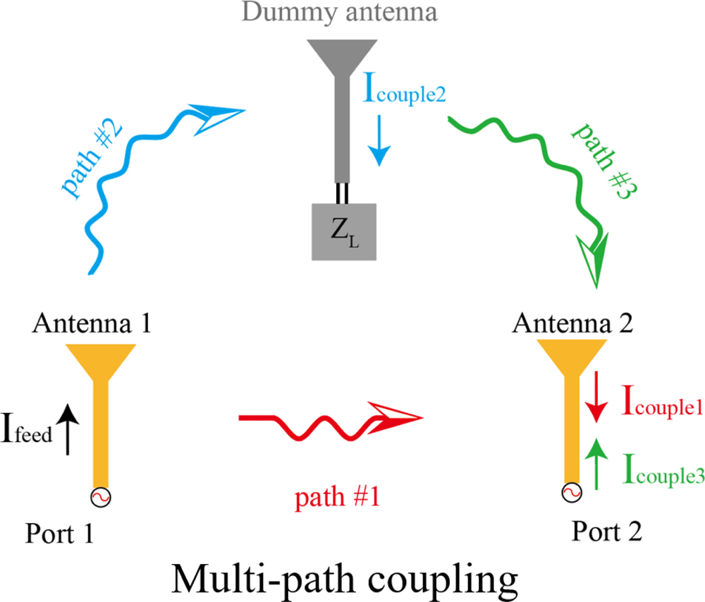
Figure 1: Decoupling diagram by using dummy antenna.
II. DECOUPLING PRINCIPLE AND THE PROPOSED ANTENNA PAIR
A. Decoupling principle
In Fig. 1, the decoupling diagram of using dummy antenna is illustrated. Port 1 and Port 2 is connected to Antenna 1 and Antenna 2, respectively. When two antenna are placed closely, coupling current I (coupling current is out-of-phase compared to the original current) will exist through the coupling path#1. The performance of Antenna 2 will be deteriorated due to the out-of-phase coupling current. To counteract this coupling current, we introduce an additional coupling current by adding a dummy antenna. As shown at the top of Fig. 1, the dummy antenna is with impedance loading of Z. Antenna 1 couples the dummy antenna through path#2 and coupling current I is created correspondingly. Energy is then transmitted from the dummy antenna to Antenna 2 through path#3, resulting in I. It should be emphasized that I and I have opposite direction. If the amplitude of I is equal to the amplitude of I, they can cancel each other out.
| (1) |
| (2) |
It is demonstrated in [25] that the coupled antenna can realize zero-coupling condition when adding dummy antenna and loading the Z of Fig. 1 calculated by (1) and (2). The R and X represent the real part and imaginary part of the Z. When the real part and imaginary part of the Z is exactly the right size of (1) and (2), respectively, then Antenna 1 and 2 are isolated. For brevity, the detailed analysis will not be shown here. It should be noted that when calculating the R and X, the dummy antenna is terminated as Port 3 in CST 2021. Therefore, in (1) and (2), the number “3” indicates the parameter of dummy antenna, i.e., Z (n3) represents the mutual impedance of the dummy antenna. After calculating the required loading impedance of the dummy antenna, a corresponding lumped element will be connected to the dummy antenna, so that the coupling current between Antenna 1 and Antenna 2 will be canceled, thus obtaining high isolation. This process will be shown later.
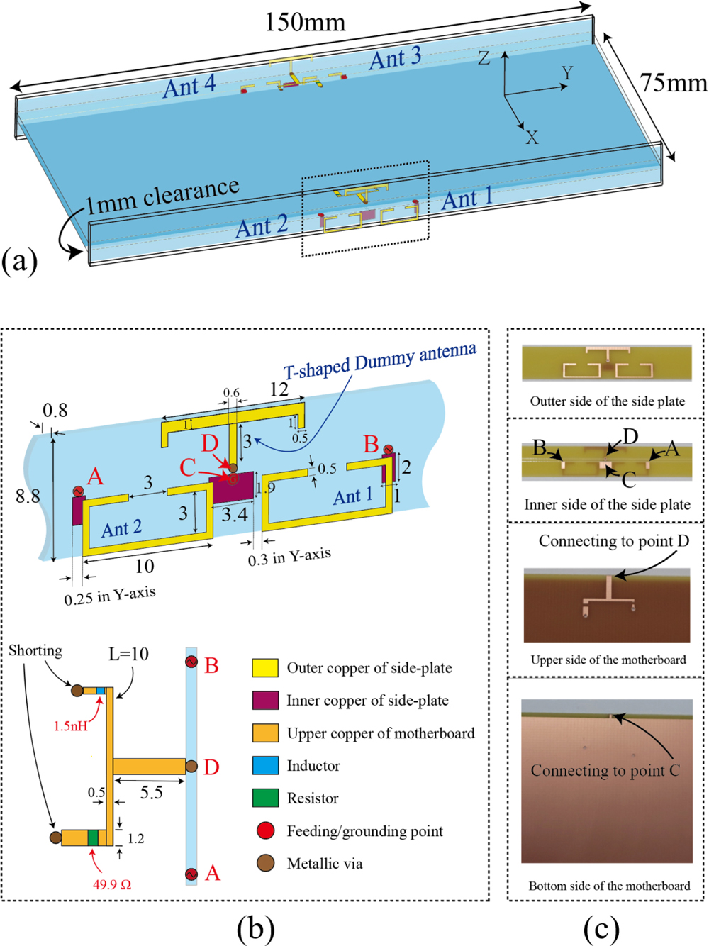
Figure 2: (a) Configuration of the proposed 44 MIMO antenna, (b) zoom-in view of the proposed antenna pair and (c) photos of the fabricated substrate.
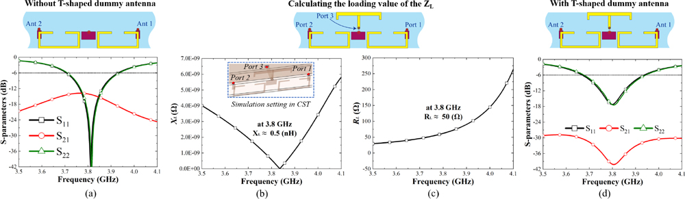
Figure 3: (a) Simulated results of antenna pair without T-shaped dummy antenna; (b) and (c) is the simulated loading requirement of the T-shaped dummy antenna, and (d) is the simulated result of antenna pair with T-shaped dummy antenna.
B. Configuration of the 44 MIMO antenna
Figure 2 shows the geometry of the 44 MIMO antenna for 5G terminal devices. A 0.8-mm-thick FR4 substrate (r = 4.4, tan = 0.02) is used as the main circuit board and two 0.8-mm-thick FR4 substrates are adopted to imitate the realistic bezels. The mainboard is perpendicular to the two bezels. The dimension of the mainboard is 15075 mm and is with 1 mm ground clearance. The detailed size is shown in Fig. 2 (b), where the side plate is double-sided copper clad. Ant. 1, Ant. 2, and the T-shaped dummy antenna are etched on the outside of the side substrate, while the feeding point A, B, and shorting point C are etched on the inside. In the upper part of the motherboard, an inductor and resistor, which has the required Z loading calculated by (1) and (2), is connected to the dummy antenna through the metallic via marked as point D. To better illustrate the connecting relationship, the enlarged view of the fabricated prototype is shown in Fig. 2 (c).
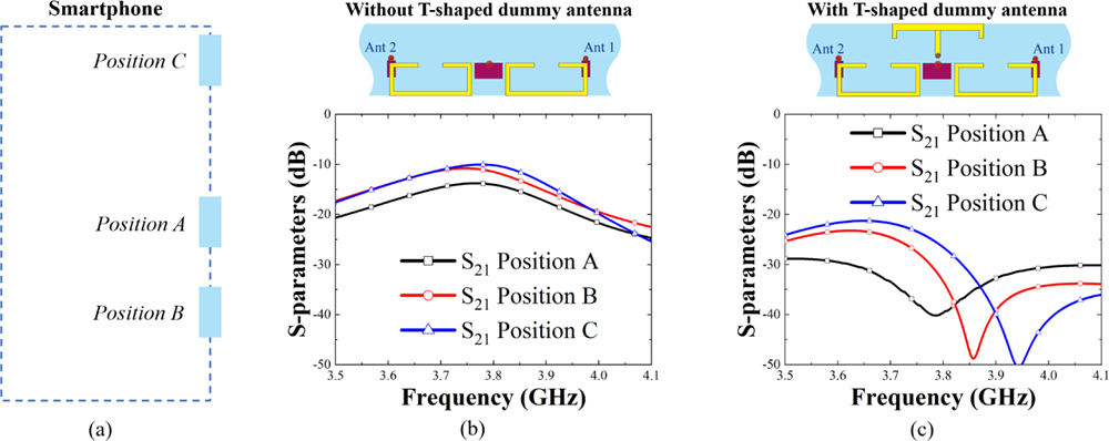
Figure 4: S-parameter of proposed antenna pair located in different places, (a) antenna placing diagram, (b) S-parameters of the antenna pair without T-shaped dummy antenna and (c) S-parameters of antenna pair with T-shaped dummy antenna.
C. Performance of adding the T-shaped dummy antenna
First, the antenna pair in Fig. 3 (a) has no T-shaped dummy antenna, which is with the impedance bandwidth of 230 MHz and the isolation is about 13 db. However, this is obviously not enough for high isolation MIMO antennas [19]-[21]. The T-shaped dummy antenna is then added above the antenna pair. Here, we use CST 2021 to calculate the loading requirement of the dummy antenna. In Figs. 3 (b) and (c), it is observed that the required loading value is X, R = 0.5 nH, 50 . Shown in Fig. 3 (d), after adding the T-shaped dummy antenna and loading the lumped elements of 0.5 nH and 49.9 , the isolation of the antenna pair is enhanced to -30 db and the impedance bandwidth is 270 MHz (17% better than before).
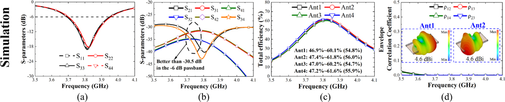
Figure 5: Simulated results of (a) reflection coefficients, (b) transmission coefficients, (c) total efficiencies, and (d) envelope correlation coefficient.
Table 1: Performance comparison of the reported antenna pair
| Ref. | Size/ | Design Difficulty | Isolation | Efficiency | Worst Isolation with Different Position |
| [19] | 0.0144 | Not easy | 20 db | 45% | 14 db |
| [20] | 0.0198 | Not easy | 24 db | 61% | N.G. |
| [23] | 0.0560 | Not easy | 21 db | 50% | N.G. |
| [24] | 0.0424 | Easy tuning | 12 db | 40% | N.G. |
| Ours | 0.0310 | Easy for calculating | 31 db | 45% | 22 db |
“N.G.” means that the data is not given.
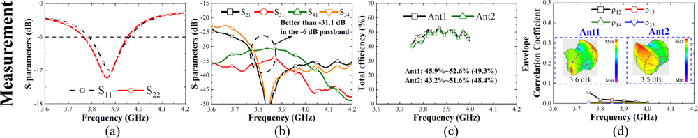
Figure 6: Measured results of (a) reflection coefficients, (b) transmission coefficients, (c) total efficiencies, and (d) envelope correlation coefficient.
Furthermore, the T-shaped decoupled dummy antenna is with robustness. As shown in Fig. 4, when the antenna pair is in a different place, such as position A and B, and C, the isolation of the antenna will change dramatically. At position C, the isolation of the antenna without the T-shaped dummy antenna is only 9 db. After the decoupling of the T-shaped dummy antenna, the isolation is still better than at 22 db even at different positions. It should be noted that the reflection coefficient of Ant. 1 and 2 is almost unchanged when the antenna is in a different place.
III. RESULTS OF THE PROPOSED 44 MIMO ANTENNA
A. Simulated results
By duplicating the antenna pair, a 44 MIMO antenna is realized. Figure 5 shows the simulated results of the proposed 44 MIMO antenna. The impedance bandwidth of the antenna is 270 MHz. After the decoupling of the T-shaped dummy antenna, the performance of S21 and S43 are greatly improved, and the worst isolation of any two antennas is 30.5 db. The average total efficiency of the antenna is 55% and the ECC is lower than 0.01 in the -6 db pass band. The high isolation between two antenna blocks, such as S31 and S41, is obtained by the characteristic of pattern diversity, which means that the Ant. 3 and 4 is located in the radiated null of Ant. 1 and 2.
B. Measured results
To verify the feasibility, the proposed antenna is fabricated and measured by a Keysight 5071C vector network analyzer. The measured data is shown in Fig. 6. Because the antenna is symmetrical, we only show the data of Ant. 1 and 2. As shown in Fig. 6 (a), the center frequency of Ant. 1 and 2 is shifted by about 50 MHz, which is mostly caused by hand-made error. The isolation of the MIMO antenna in the -6 db pass band is better than -31.1 db. The measured average total efficiency of the antenna is 49% and the ECC is lower than 0.05. In the illustration of Fig. 6 (d), we show the measured 3D pattern of the antenna. The measured results are in high agreement with the simulated ones.
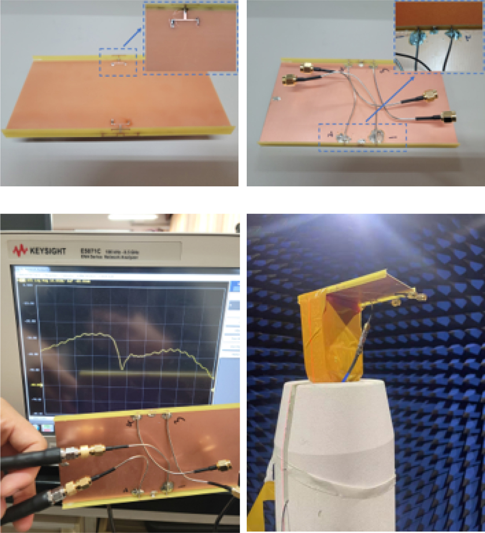
Figure 7: Fabricated prototype and measurement setup.
The fabricated prototype and measurement setup is shown in Fig. 7. The proposed antenna pair is connected to a 50 semi-rigid cable, where its outer side is connected to ground.
C. Performance comparison
To show the superiority of the design strategy, performance comparison including electrical size, design difficulty, isolation, efficiency, and the worst isolation with different antenna position is given in Table 1. It is observed that the proposed antenna pair obtain the highest isolation of 31 db in a compact size. The tuning process is easy and relatively high antenna efficiency is obtained. More importantly, the proposed antenna pair still has high isolation when the antenna position changes. The proposed 44 MIMO antenna has great potential to be applied in 5G mobile devices.
Furthermore, in [12], a method to miniaturize the aperture of a dual-polarized Quadruple-Folded-Dipole (QFD) antenna by bending its arms downward or upward is proposed. Both antennas can achieve relatively small apertures while ensuring good matching, isolation and radiation performances within the band of interest. In [13], a ceramic superstrate-based decoupling method (CSDM) is proposed to reduce the mutual coupling between two closely packed dipole antennas while maintaining cross-polarization suppression. However, they have one disadvantage: the decoupled dipole is relatively large in volume, and is placed vertically, which is suitable for application to base station antennas. Our design is mainly aimed at 5G terminal equipment, with small size, low height and high isolation. Based on practical applications, we think our design is more suitable for 5G terminal devices.
IV. CONCLUSION
In this paper, a compact antenna pair with high isolation and robustness to antenna position for 5G mobile devices is proposed and analyzed. The proposed antenna pair comprises of an antenna pair with pattern diversity characteristics and a compact T-shaped decoupling structure. By duplicating the proposed antenna pair, a 44 MIMO antenna is realized. The isolation and robustness of the MIMO antenna are improved by introducing an impedance-loaded T-shaped decoupling dummy antenna. The measurement results of the proposed MIMO antenna show that it is with isolation of 31 db. The measured average antenna efficiency is 49% and the ECC is below 0.05. The proposed MIMO antenna has great potential for application in 5G mobile devices.
REFERENCES
[1] M.-Y. Li, Y.-L. Ban, Z.-Q. Xu, C.-Y. Sim, K. Kang, and Z.-F. Yu, “Eight-port orthogonally dual-polarized antenna array for 5G smartphone applications,” IEEE Trans. Antennas Propag., vol. 64, no. 9, pp. 3820-3830, Sep. 2016.
[2] K. L. Wong, J.-Y. Lu, L.-Y. Chen, W.-Y. Li, and Y.-L. Ban, “8-antenna and 16-antenna arrays using the quad-antenna linear array as a building block for the 3.5-GHz LTE MIMO operation in the smartphone,” Microw. Opt. Technol. Lett., vol. 58, no. 1, pp. 174-181, Jan. 2016.
[3] Y. Li, C.-Y.-D. Sim, Y. Luo, and G. Yang, “12-port 5G massive MIMO antenna array in sub-6 GHz mobile handset for LTE bands 42/43/46 applications,” IEEE Access, vol. 6, no. 9, pp. 344-354, Oct. 2017.
[4] Z. Qin, W. Geyi, M. Zhang, and J. Wang, “Printed eight-element MIMO system for compact and thin 5G mobile handset,” Electron. Lett., vol. 52, no. 6, pp. 416-418, Mar. 2016.
[5] Y.-L. Ban, C. Li, C.-Y.-D. Sim, G. Wu, and K.-L. Wong, “4G/5G multiple antennas for future multi-mode smartphone applications,” IEEE Access, vol. 4, pp. 2981-2988, Jul. 2016.
[6] Y. H. Wang, X. Wang, J. L. Wang, and R. Shao, “Dual-band highly isolated eight-element MIMO antenna for 5G mobile phone,” Applied Computational Electromagnetics Society (ACES) Journal, vol. 37, no. 5, pp. 588-596, Nov. 2022.
[7] N. O. Parchin, O. M. Dardeer, A. S. Amar, C. H. See, and R. Abd-Alhameed, “Dual-band phased array 5G mobile-phone antenna with switchable and hemispherical beam pattern coverage for MIMO-diversity communications,” Applied Computational Electromagnetics Society (ACES) Journal, vol. 36, no. 12, pp. 1602-1609, Mar. 2022.
[8] G. We and Q. Feng, “Side-frame dual-band MIMO antennas for 5G smartphone applications,” Applied Computational Electromagnetics Society (ACES) Journal, vol. 35, no. 11, pp. 1314-1315, Nov. 2020.
[9] Z. An and M. He, “A multiband dual-antenna system for MIMO operation in mobile terminals,” Applied Computational Electromagnetics Society (ACES) Journal, vol. 34, no. 10, pp. 1529-1534, Oct. 2019.
[10] R. M. Asif, A. Aziz, M. Amjad, Majid N. Akhtar, A. Baqir, and M. N. Abbasi, “Analysis and design of an efficient and novel MIMO antenna for 5G smart phones using FDTD and FEM,” Applied Computational Electromagnetics Society (ACES) Journal, vol. 36, no. 3, pp. 266-272, Mar. 2021.
[11] Y. Li, W. Li, and W. Yu, “A multi-band/UWB MIMO/diversity antenna with an enhanced isolation using radial stub loaded resonator,” Applied Computational Electromagnetics Society (ACES) Journal, vol. 28, no. 1, pp. 8-20, Jan. 2013.
[12] H. Yang, G. Zhao, J. Jiang, T. Liu, L. Zhao, Y. Li, Y. Cai, and J. Yao. “Aperture reduction using downward and upward bending arms for dual-polarized quadruple-folded-dipole antennas,” IEEE Antennas and Wireless Propagation Letters, vol. 22, no 3, pp. 645-649, Mar. 2023.
[13] F. Liu, J. Guo, L. Zhao, G.-L. Huang, Y. Li, and Y. Yin, “Ceramic superstrate-based decoupling method for two closely packed antennas with cross-polarization suppression,” IEEE Trans. Antennas Propag., vol. 69, no. 3, pp. 1751-1756, Mar. 2021.
[14] C.-Y. Chiu, C.-H. Cheng, R. D. Murch, and C. R. Rowell, “Reduction of mutual coupling between closely-packed antenna elements,” IEEE Trans. Antennas Propag., vol. 55, no. 6, pp. 1732-1738, Jun. 2007.
[15] F. Yang and Y. Rahmat-Samii, “Microstrip antennas integrated with electromagnetic band-gap (EBG) structures: A low mutual coupling design for array applications,” IEEE Trans. Antennas Propag., vol. 51, no. 10, pp. 2936-2946, Oct. 2003.
[16] M. Li, M. Y. Jamal, L. Jiang, and K. L. Yeung, “Isolation enhancement for MIMO patch antennas sharing a common thick substrate: Using a dielectric block to control space-wave coupling to cancel surface-wave coupling,” IEEE Trans. Antennas Propag., vol. 69, no. 4, pp. 1853-1863, Apr. 2021.
[17] S. C. Chen, Y. S. Wang, and S. J. Chung, “A decoupling technique for increasing the port isolation between two strongly coupled antennas,” IEEE Trans. Antennas Propag., vol. 56, no. 12, pp. 3650-3658, Dec. 2008.
[18] A. Diallo, C. Luxey, P. Le Thuc, R. Staraj, and G. Kossiavas, “Study and reduction of the mutual coupling between two mobile phone PIFAs operating in the DCS1800 and UMTS bands,” IEEE Trans. Antennas Propag., vol. 54, no. 11, pp. 3063-3074, Nov. 2006.
[19] L. Chang, Y. Yu, K. Wei, and H. Wang, “Orthogonally polarized dual antenna pair with high isolation and balanced high performance for 5G MIMO smartphone,” IEEE Trans. Antennas Propag., vol. 68, no. 5, pp. 3487-3495, May 2020.
[20] H. Xu, S. S. Gao, H. Zhou, H. Wang, and Y. Cheng, “A highly integrated MIMO antenna unit: Differential/common mode design,” IEEE Trans. Antennas Propag., vol. 67, no. 11, pp. 6724-6734, Nov. 2019.
[21] L. Sun, H. Feng, Y. Li, and Z. Zhang, “Compact 5G MIMO mobile phone antennas with tightly arranged orthogonal-mode pairs,” IEEE Trans. Antennas Propag., vol. 66, no. 11, pp. 6364-6369, Nov. 2018.
[22] K.-L. Wong, C.-Y. Tsai, and J.-Y. Lu, “Two asymmetrically mirrored gap-coupled loop antennas as a compact building block for eight-antenna MIMO array in the future smartphone,” IEEE Trans. Antennas Propag., vol. 65, no. 4, pp. 1765-1778, Apr. 2017.
[23] H. Xu, H. Zhou, S. Gao, H. Wang, and Y. Cheng, “Multimode decoupling technique with independent tuning characteristic for mobile terminals,” IEEE Trans. Antennas Propag., vol. 65, no. 12, pp. 6739-6751, Dec. 2017.
[24] J. Guo, L. Cui, C. Li, and B. Sun, “Side-edge frame printed eight-port dual-band antenna array for 5G smartphone applications,” IEEE Trans. Antennas Propag., vol. 66, no. 12, pp. 7412-7417, Dec. 2018.
[25] B. K. Lau and J. B. Andersen, “Simple and efficient decoupling of compact arrays with parasitic scatterers,” IEEE Trans. Antennas Propag., vol. 60, no. 2, pp. 464-472, Feb. 2012.
BIOGRAPHIES

Junlin Wang received his PhD degree in Instrument Science and Technology from North University of China. He is currently working at the School of Electronic Information Engineering, Inner Mongolia University, Hohhot, China. His research interests are in micro and nano RF devices (antennas, filters, couplers, etc.), and metamaterial antennas.

Xiaomin Chen received his B.E. degree in Electronic Information Science and Technology from Shaoguan University. He is currently pursuing a master’s degree in Information and Communication Engineering at Inner Mongolia University, Hohhot, China. His research interest is in 5G mobile terminal antennas.

Xin Wang received her PhD degree in Instrument Science and Technology from North University of China. She is currently working at the School of Electronic Information Engineering, Inner Mongolia University, Hohhot, China. Her research interests are in micro and nano RF devices (antennas, filters, couplers, etc.), and metamaterial antennas.

Min Wei received her B.E. degree in Electronic Information Science and Technology from Hexi University. She is currently pursuing a master’s degree in Information and Communication Engineering at Inner Mongolia University, Hohhot, China. Her current research interest is in 5G mobile terminal antennas.
ACES JOURNAL, Vol. 37, No. 12, 1225–1231
doi: 10.13052/2022.ACES.J.371206
© 2022 River Publishers