A Simple Interference and Power-based Direction of Arrival Measuring System for Modern Communication
Nga Vu, Thinh Le, Minh Dinh, and Minh Thuy Le
1School of Electrical and Electronic Engineering
Hanoi University of Science and Technology, 11515, Vietnam
2École normale supérieure Paris-Saclay
Université Paris-Saclay, 91190, France
3College of Engineering
University of North Texas, 76205, Texas, USA
4Department of Electrical and Computer Engineering
University of Southern California, 90089, California, USA
Corresponding author: thuy.leminh@hust.edu.vn
These authors contributed equally to the work.
Submitted On: October 21, 2022; Accepted On: May 10, 2023
ABSTRACT
In this paper, we present a system specialized for measuring the direction-of-arrival (DoA) of electromagnetic waves with noticeable simplicity. Unlike common methods, which are based heavily on complex computation and signal processing, our proposed system is considerably simpler, both in terms of design and operating theory. Our design consists of two directional antennas for collecting incident waves, a system of Wilkinson power combiners and dividers in which the waves collected by the antennas interfere, a result-processing block consisting of power amplifiers, rectifiers, and a microcontroller unit that respectively converts the interferometric radio-frequency (RF) signal into direct-current (DC) signal, measures its corresponding power before calculating the incident angle solely based on a simple trigonometric equation. The system yields a high accuracy of less than with the incident angle ranging from to .
Index Terms: antennas, direction-of-arrival, interferometry, power amplifier, Wilkinson power divider.
I. INTRODUCTION
Measuring the direction-of-arrival (DoA) has attracted extensive concern from researchers since the first days of the microwave. In recent years, DoA estimation plays a crucial role due to its diverse application, especially in modern wireless communication. One well-known example that needs DoA measurement is wireless power transfer (WPT) in which power is transmitted via electromagnetic waves. Moreover, recently, integrating WPT with wireless communication has been flourishing [1, 2, 3]. However, a common challenge for such a strategy is the low efficiency [4], [5] because the receiver direction is unknown. Thus, measuring the DoA to adjust the receivers’ direction is essential to increase efficiency of the system. One of the most efficient solutions for this issue is integrating the DoA system to maximize the transmitted energy to receivers while minimizing the transmitting power to interference sources. The other application of DoA estimation is passive remote sensing where the receiving signals have different amplitudes and phases due to the reflecting surface. In such cases, DoA estimation must be employed to detect the direction of receiving signals, from which the reflecting surface informationis determined.
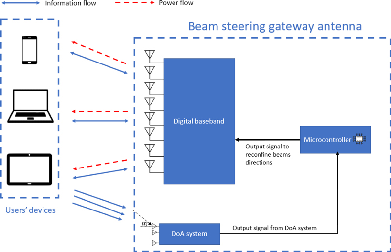
Figure 1: Integrated DoA system in Simultaneous Wireless Information and Power Transfer (SWIPT) technology applied for beam steering gateway antenna.
Based on the main parameters of a signal, the direction-finding method can be categorized into power-based, frequency-based, and phase-based. One of the most common power-based direction-finding methods is the Watson-Watt principle. This structure contains two crossed-loop antennas and a reference one. The incident angle is determined by the voltage ratio between the two receiving antennas. Although this method has a simple principle and the system is compact, it has a low resolution. The frequency-based method can be realized by using the Doppler principle that is the frequency of incident wave changes when the receiving point moves. Therefore, by determining the instantaneous frequency shift of a receiving antenna, the DoA can be calculated [6]. Although this method has better performance than the Watson-Watt method, it requires an extensive response time because of the huge number of receiving antenna elements. Finally, the phase-based direction-finding can be realized by interferometry in which the DoA can be determined by measuring the power of output signals of an interferometer thanks to the direct relation between DoA and phase difference between antenna elements. In [7], the DoA error is around 1 within the range of 12 to 90. Besides, the subspace DoA estimation such as multiple signal classification (MUSIC) and estimation of signal parameters via rotational invariance technique (ESPRIT). They are both well-known for high accuracy and high-resolution DoA estimation methods [8]. Another algorithm used in uniform circle array was proposed in [9] and another new one based on Pencil Method used for the uniform rectangular array was mentioned in [10]. However, they all require a certain complexity of a massive number of receiving antennas. The interferometry method requires the use of Michelson interferometers, which work well for optical spectrum, but become very bulky when scaling to the RF frequencies. Thus, they are not considered a suitable solution for low-power, easily integrated into other systems.
To satisfy the requirements of an easily integrated DoA system that has a small and simple structure and low-power consumption, in this project, we introduce a simple power-based DoA system consisting of a direction-finding unit and a data processing unit. The first part contains two basic receiving antennas which receive the incident waves and a network of Wilkinson power combiners and dividers (WPDs), in which the waves received by the antennas interfere. The other part contains low-noise amplifiers, RF rectifiers, DC amplifiers, and a microcontroller unit. The angle of incident waves is determined based on the power of output signals of the DoA unit in the proposed DoA system. The system’s error is less than 7.5 in the measuring range of -60 to 60.
II. PROPOSED DoA SYSTEM
This section presents explicitly the structure as well as the working principle of the proposed system. By analyzing the principle, this work provides the equation needed for calculating the DoA of the incident wave.
The system composes of a DoA sensor unit which has two receiving antennas and a network of power dividers and a power combiner, a data processing and measuring unit composes of three RF low noise amplifiers (LNA), three RF rectifiers, a DC amplifier circuit, a microcontroller, and finally a computer to process signals. The system operates at 2.6 GHz. The signal path is denoted by the black arrow in Fig. 1. The workflow of the system is as follows: Incident waves come to the DoA sensor unit. The signals received by the two antennas
interfere and go out at the three output ports. These three output waves go into the data processing and measuring unit. In this unit, the waves are rectified and amplified twice (once by the LNA and then by DC amplifier) so that the analog-to-digital converter (ADC) of the microcontroller (MCU) can detect the signals. The DoA can be evaluated and displayed on a computer’s screen.
A. DoA sensor unit
The structure of the proposed DOA sensor unit is illustrated in Fig. 2. This unit consists of two directional receiving antennas separated from each other by a distance of mm along with WPDs. When incident waves arrive with the incident angle , the received power at ports 1, 2, and 3 are , , and , respectively. Signal paths from antenna 1 and antenna 2 in the DOA sensor are denoted by the red and blue lines.

Figure 2: The structure of DoA sensor unit.
Received signals from two antennas go through two power divider circuits. Thus, half of the received powers by antenna 1 and antenna 2 go to port 1 and port 2, respectively. Whereas the other two halves continuously go through a power combiner. Here, the signals from antenna 1 and antenna 2 interfere with each other. As a result, the output signal at port 3 is the summation of the half-received power of port 1 and the one of port 2. By measuring magnitudes of output power at output ports, the DoA will be calculated via asimple equation.
Let us label the received power on antenna 1 and antenna 2 as P and P’, respectively. When this power goes through the power dividers, it is easily deduced that the magnitudes of the power at port 1 and port 2 are and , respectively. The output signal of port 3 is the sum of interference of the two components from power dividers which is and , respectively. The phase difference between the two receiving signals is:
| (1) |
where is the distance between two receiving antennas and is the angle of the incident wave and is the wavelength of incident waves. The corresponding currents going from antenna 1, antenna 2, and at ports 3 are , , and . The total current is the vector summation of and . Therefore, is calculated by the Cosinerule as:
| (2) |
To determine the power and currents on the power combiner, we analyze a Wilkinson circuit including quarter wavelength transformers with characteristic impedance ( is the impedance of terms at ports) and an isolating resistor 2 in even and odd modes with respect to the source at port 2. In the even mode, because of the symmetry, the symmetric plane of the circuit is open circuited, as illustrated in Fig. 3. Because both halves of the circuit are the same, for simplicity, we consider one of them. Ignoring open components, the circuit only includes the quarter wavelength transformer and the load 2, which is shown in Fig. 3.

Figure 3: The equivalent and upper half circuits of Wilkinson power divider in the even (a, b) and odd (c, d) modes.
The input impedance seen from port 2 is:
| (3) |
Thus, in this mode, no current goes through the isolation resistor, the signal only goes on the quarter wavelength transformer and the load at port 1. On the other hand, in the odd mode, the symmetric plane of the circuit becomes short-circuited as shown in Fig. 3 and the upper half is illustrated in Fig. 3. The quarter wavelength transmission line with a short-circuited end is equivalent to an open circuit. So, the circuit only has the resistor . It means that in the odd mode signal, the current only goes through the isolation resistor. To sum up, the current going out at port 1 with the source at port 2 is the current in the even mode and the input impedance seen from port 2 is . Moreover, each output port of the power divider is connected to an LNA which has input impedance of 50. Therefore, the output power at output ports can be represented based on three currents , , and as follows:
| (4) | ||||
| (5) | ||||
| (6) |
Equation (2) becomes:
| (7) |
Replacing the equation (1) into equation (7), the angle of the incident wave is calculated as follows:
| (8) |
B. Data processing and measuring unit
According to the working principle of the proposed device, we chose two dipole Yagi Uda antennas that have directional radiation patterns and compact size working at 2.6 GHz. The antennas dimensions were calculated and simulated. The radiation pattern of the manufactured antennas is shown in Fig. 4. The measured data indicates that the antennas are directive with a maximum gain of 6.52 dBi and high efficiency of 98.38.
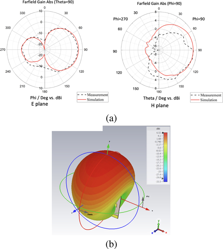
Figure 4: The simulated and measured radiation pattern of Yagi Uda antenna (a) and 3D radiation pattern and (b) at 2.6 GHz.
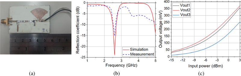
Figure 5: (a) Manufactured rectifier, (b) Reflection coefficient, and (c) open-load output voltage of RF rectifier.
To calculate the DoA , the values of power at three output ports of the DoA sensor have to be measured. The data processing and measuring unit measure all the mentioned signals and use an algorithm to calculate DoA . In general, this unit contains four main parts: LNA, RF rectifiers, DC amplifiers, microcontroller, andMATLAB processing.
For LNA, we use the SBB5089 RF Power amplifier module which is designed for high linearity and minimal external components. By performing the measurement, all three LNA are shown to have a gain of 14 to 15 dB at 2.6 GHz with input power from -10 to 0 dBm.
Rectifier is one major part in the data processing block. Its main function is to convert AC voltages, which are amplified by the LNA, into DC voltages, which will be the inputs of the DC power amplifier before going to the microcontroller. Therefore, the rectifier effectively determines the efficiency and accuracy of thereceived signals.
The rectifiers consists of multiple parallel connected half-wave voltage doublers. The SMS7630 Schottky diode is chosen due to its high efficiency performance at low input power [11] with a 39 pF capacitor. Since the application of this work is for far-field SWIPT, the incident power is usually small. Therefore, in the DC filter part of the rectifier we use a radial stub instead of a lumped capacitor to minimize power loss due to welding. The commonly seen impedance matching stub is also employed to match the input impedance of the rectifier with output impedance of the LNA which is 50 , as shown in Fig. 5 (a). The dimensions of microstrip lines are carefully calculated to tune the input impedance of the circuits to 50 at 2.6 GHz. The design and simulation processes are conducted in ADS software in which the feed line is modeled as an AC source with 50 impedance and the diode is modeled using the SPICE model. The parasitic inductance and capacitance of the diode is also considered. The requirement for the rectifiers is to create an output DC voltage as large as possible so they are designed with open ends. The simulation and measurement results are shown in Fig. 5. It is evident that the circuit resonates at 2.6 GHz. Output voltages of the three manufactured rectifiers range from 150 mV to 300 mV at 0 dBm input and go up as the input power increases. The plot of Fig. 5 (c) is stored as the data set of MATLAB program in 0.5 dBmresolution.
The output voltage of the RF rectifier is still low, and with a small input (below -10 dB) the output signal is noisy and brings errors. To solve this problem, a DC power amplifier is employed to amplify the output DC signal from the rectifiers and as well as to flattenthis signal.
The measured DC voltages are processed in the following procedure: First, the STM32 microcontroller measures all three voltages. Then the processor uses the power voltage relation provided in Fig. 5 (c) to estimate the amount of power received by each antenna as well as the interference sum on Port 3. The Interpolation Technique is applied to calculate missing data in the input data set of Fig. 5 (c). Subsequently, using equation (8) which is a simple trigonometric equation, the DoA can be achieved and is printed on the screen.
III. EXPERIMENTAL VERIFICATION
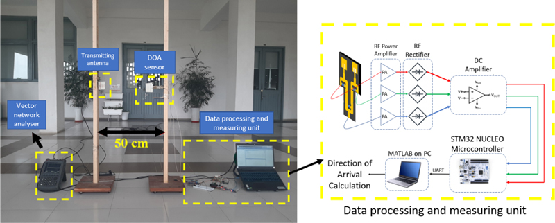
Figure 6: Experiment configuration to examine the accuracy of the proposed DoA system.
Table 1: Comparison DoA measuring performance between the proposed and other systems
| References | Working Frequency | Measuring Range | Error | Method |
| [7] | 2.65 GHz | to | Less than | Photonic-based |
| [12] | 2.45 GHz | to | to | Based on harmonic reradiation |
| [13] | 10 GHz | to | Less than | Photonic-based |
| This work | 2.6 GHz | to | Less than | Power-based |
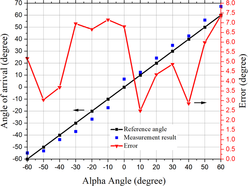
Figure 7: The measurement result.
The measurement system was put under-examinaion. The experiment configuration in real-life is displayed and all components are connected as described in Fig. 6. The incident wave, 0 dBm in strength, was generated by a Keysight E5080B ENA Vector Network Analyzer (VNA) and transmitted via a 6 dBi-gain reference Yagi antenna, placed 50 centimeters away from the system-under-test, comfortably inside the far-field of all antennas. All obstacles within a 50 centimeters radius were removed while all wireless sources in the proximity were turned off. In addition, we attached a needle indicator that is parallel to the reference line on the plinth of the rotating pillar. Hence, when we rotate the pillar with the attached DoA sensor, the needle indicator will clarify the true value of DoA. The processor and PC measured, calculated, and estimated the DoA every time the reset button of the processor was pressed. The DoA value was automatically calculated and displayed on the PC screen. In the experiment setup, the excited wave traveled to the receiving antennas at elevation angle. Since the designed distance between two receiving antennas is 70 mm, the measurable DoA range should be from to . In the experiment, the azimuth angle was varied in this range with a step. The measured DoA result as displayed in Fig. 7 yields high accuracy, and only differs as much as from the ground truth. The major reason for the error is that when we rotate the receiving antennas in the experiment, which will create a larger DoA value, the energy density around the two antennas will not be the same. The main idea of this paper is to determine DoA based on power received by each antenna, so the balance of energy density of both antennas is really important. Therefore, the difference in this value as mentioned will affect the measured result. The other reason would be due to the mismatch between each device in the data processing and measuring unit. To have the best output result, the devices in each output power port need to be identical. However, due to the lack of accuracy in the manufacturing process, there were some mismatch happened. These imprecisions, overall, have contributed to the error in the final result.
Table 1 shows the comparison of this work and several previous works. It can be seen that the proposed DoA system possesses a simpler structure as it is only compose of two receiving antennas and simple passive circuits that are the WPDs, while the system in [7] and [13] consists of Mach Zehnder modulation utilizing the laser source. The DoA estimation system in [12] is just two receiving microstrip antennas, which is too simple, leading to a narrow measuring angle compared to other works. The power-based DoA also was proposed in some previous works such as [14] and [15]. However, they mainly focused on a part of the DoA system which is antenna configuration. The simple, complete DoA system like this work, to the best of our knowledge, has not yet been studied. With a wide measuring angle range and highly simple structure, the proposed DoA system has big potential to be widely applied in practical structures such as WIPT.
IV. CONCLUSION
In conclusion, we have proposed and empirically investigated an alternative approach to measure the DoA of microwave signals based on interference. The proposed system consists of a DoA sensor and a data processing unit and yields less than a error in the tested range of to . The advantages of this method are its simple structure, compactness, low cost, and ease of manufacture as well as being a potential candidate for the DoA finding devices integrated in the gateway system using SWIPT technology.
REFERENCES
[1] S. Zouaoui, M. Souilem, W. Dghais, A. Radwan, S. Barmada, and M. Tucci, ‘‘Wireless power transfer and data communication cognitive radio through two-coil inductive channel,” IEEE Global Communications Conference (GLOBECOM), Waikoloa, HI, USA, Feb. 2019.
[2] B. Clerckx, R. Zhang, R. Schober, D. Ng, D. Kim, and H. Poor, “Fundamentals of wireless information and power transfer: From RF energy harvester models to signal and system designs,” IEEE Journal on Selected Areas in Communications, vol. 37, pp. 4-33, Jan. 2019.
[3] B. Clerckx, K. Huang, L. Varshney, S. Ulukus, and M.-S. Alouini, “Wireless power transfer for future networks: Signal processing, machine learning, computing, and sensing,” IEEE Journal of Selected Topics in Signal Processing, Aug. 2021.
[4] T. D. P. Perera, D. N. K. Jayakody, S. Chatzinotas, and V. Sharma, “Wireless information and power transfer: Issues, advances, and challenges,” IEEE 86th Vehicular Technology Conference (VTC-Fall), pp. 1-7, 2017.
[5] D. W. K. Ng, T. Q. Duong, C. Zhong, and R. Schober, The Era of Wireless Information and Power Transfer, Wiley Telecom, 2019.
[6] D. Peavey and T. Ogumfunmi, “The single channel interferometer using a pseudo-Doppler direction finding system,” IEEE International Conference on Acoustics, Speech, and Signal Processing, Apr. 1997.
[7] H. Chen and E. H. W. Chan, “Simple approach to measure angle of arrival of a microwave signal,” IEEE Photonics Technology Letters, vol. 31, pp. 1795-1798, Oct. 2019.
[8] O. A. Oumar, M. F. Siyau, and T. P. Sattar, “Comparison between MUSIC and ESPRIT direction of arrival estimation algorithms for wireless communication systems,” International Conference on Future Generation Communication Technology, pp. 99-103, 2012.
[9] Y. Tian, Y. Huang, X. Zhang, M. Lin, and X. Qiao, “A robust algorithm for DOA estimation of coherent sources with UCA,” Applied Computational Electromagnetics Society (ACES) Journal, vol. 37, no. 6, pp. 692-701, 2022.
[10] A. Azarbar, G. R. Dadashzadeh, and H. R. Bakhshi, “2-D DOA estimation with matrix pencil method in the presence of mutual coupling,” Applied Computational Electromagnetics Society (ACES) Journal, vol. 27, no. 9, pp. 742-748, 2012.
[11] S. Hemour, Y. Zhao, C. H. P. Lorenz, D. Houssameddine, Y. Gui, C.-M. Hu, and K. Wu, “Towards low-power high-efficiency RF and microwave energy harvesting,” IEEE Transactions on Microwave Theory and Techniques, vol. 62, no. 4, pp. 965-976, 2014.
[12] S. K. Tomohiko Mitani and N. Shinohara, “Direction-of-Arrival estimation by utilizing harmonic reradiation from rectenna,” IEEE Wireless Power Transfer Conference (WPTC), Feb. 2018.
[13] L. Peng, Y. Lianshan, Y. Jia, F. Xia, P. Wei, L. Bin, Z. Xihua, Z. Tao, and C. Zhiyu, “Photonic approach for simultaneous measurements of Doppler-frequency-shift and angle-of-arrival of microwave signals,” Optics Express, vol. 27, pp. 8709-8716, Feb. 2019.
[14] Y. Han, Q. Fang, L. Song, F. Yan, X. Qiao, and S. Zhuang, “DOA estimation for unequal power sources using extremely low profile aperture coupled microstrip antenna,” Applied Computational Electromagnetics Society (ACES) Journal, vol. 31, no. 9, pp. 1100-1109, 2016.
[15] R. Pohlmann, S. Zhang, T. Jost, and A. Dammann, “Power-based direction-of-arrival estimation using a single multi-mode antenna,” 14th Workshop on Positioning, Navigation and Communications (WPNC), Jan. 2018.
BIOGRAPHIES

Nga Vu received her B.Sc. degree in Control and Automation Engineering from the School of Electrical and Electronic Engineering of Hanoi University of Science and Technology in 2021. She is currently doing a Master’s at École normale supérieure Paris-Saclay - Université Paris-Saclay, France. Her research interest is applied electromagnetics.

Thinh Le received his B.Sc. degree in Control and Automation Engineering from the School of Electrical and Electronics Engineering of Hanoi University of Science and Technology in 2022. He is currently doing a Master’s at University of North Texas, USA. His research interests is applied electromagnetics.

Minh Dinh received his B.Sc. degree from Hanoi University of Science and Technology in 2021. He is currently pursuing his doctorate in Electrical Engineering at the University of Southern California, USA. His research interest is photonics.

Minh Thuy Le received her B.Sc. and M.S. degrees in Electrical Engineering from Hanoi University of Science and Technology in 2006 and 2008, respectively, and Ph.D.degree in Optics and Radio Frequency from Grenoble Institute of Technology, France in 2013. She is currently an Assoc. Prof. and a group leader of the Radio Frequency group at the Smart Sensor Laboratory, School of Electrical and Electronic Engineering (SEEE), Hanoi University of Science and Technology (HUST). Her research interests include build-in antenna, antenna array, beamforming, metamaterials, energy harvesting and wireless power transfer.
ACES JOURNAL, Vol. 38, No. 5, 325–332
doi: 10.13052/2023.ACES.J.380505
© 2023 River Publishers