A Novel Ultra-Wideband Wide-angle Scanning Sparse Array Antenna using Genetic Algorithm
Z. N. Jiang, Y. Zheng, X. F. Xuan, and N. Y. Nie
1School of Electronic Science and Applied Physics,
Hefei University of Technology, Hefei, China, 230009
2National Mobile Communications Research Laboratory,
Southeast University, Jiangsu, 210096
jiangzhaoneng@hfut.edu.cn
Submitted On: October 24, 2022; Accepted On: January 2, 2023
ABSTRACT
A single-element antenna is usually unable to meet the communication requirements of the wireless system and the main solution is to use an array antenna. The desire to reduce the weight and cost of the array antenna gave rise to the sparse array. A linearly polarized sparse array antenna with ultra-wideband wide-angle scanning characteristics based on a genetic algorithm (GA) is developed in this paper. The antenna array consists of 40 units, which are arranged by a rectangular array with a side length of 300 mm. Compared to the conventional periodic array, the proposed sparse array has reduced about 190 antenna elements. The sparse array can achieve S11 10 dB in the ultra-wideband of 2.7–12 GHz (120%). Experimental results for the proposed antenna exhibit an azimuth scanning angle of 45, and a pitching scanning angle of 30.
Index Terms: genetic algorithm (GA), linearly polarized, sparse array, ultra-wideband, wide-angle scanning.
I. INTRODUCTION
With the rapid development of modern communication technology, the antenna is indispensable as the carrier of electromagnetic waves and current conversion. In some specific engineering applications, the antenna is required to have high gain and strong directivity, or the antenna pattern can be scanned, then a single antenna is often not qualified. The main method to solve the problem is to adopt an array antenna.
Periodic arrays are widely used due to the convenience of mathematical treatment and assembly of the array structure. In general, the main lobe resolution of an array is inversely proportional to the aperture. If the periodic array is required to have high resolution, the aperture will be large, leading to an increase in the number of array elements and production costs [1]. On this basis, to reduce the cost and system complexity, it is generally expected to design the large array into a sparse array or sub-array form. The sparse array is used to randomly sparse on the same aperture as the full array [2]. The array element spacing is usually not fixed and can be any value. The sparse array can satisfy the required radiation characteristics with fewer array elements, which not only simplifies the antenna structure and feed network, reduces the overall weight of the system, but also greatly reduces the cost of the system [3]. In the optimized design of a sparse antenna array, unequally spaced array element positions lead to a complicated nonlinear optimization. To solve this problem, setting the element spaces as integer multiples of a suitably chosen basic spacing simplifies the design procedure. As GA possesses intrinsic flexibility to a nonlinear problem, it is mature in optimizing the unequally spaced arrays. In addition, some antennas based on GA are proposed [4–6].
Due to the above advantages of a sparse array, the United States carried out related research on the synthesis of sparse arrays in the 1960s and successfully applied the sparse array to HAPDAR radar [7]. The same beam width and side-lobe level can be achieved when the number of sparse array elements is 50% of the full array. With the rapid development of sparse array technology, it has been well applied in Cobra Dane [8], TechSat21 space-based radar [9], SIAR, Sea-based X-band radar (SBX), SKA giant Square Kilometer Array [10], and other systems. Some ultra-wideband phased array antennas have been proposed [11–13]. Compared with this literature, The paper has some advantages as shown in Table 2.
Referring to the literature, it can be seen that most of the researchers on sparse array focus on the optimization of the algorithm, which only focuses on the theoretical part and less on the practical part [14]. This paper focuses on the practical part, and a novel sparse array based on a genetic algorithm is systematically designed, optimized, and fabricated. Considering that the practice environment is a missile-borne antenna, how to design an ultra-wideband array antenna with wide-angle scanning, lightweight and high integration are difficult. Through many experiments, the log periodic dipole antenna (LPDA) with an exponential shape is selected as the antenna element. The overall sparse array can operate from 2.7 to 12 GHz (120%) with 40 antenna elements. Simulation results show that the beam pointing accuracy is better than 10 degrees, the azimuth scanning angle is 45, and the pitching scanning angle is 30. It is shown that the proposed sparse array significantly reduces the number of antenna elements.
II. DESIGN PROCESS
A. Sparse configuration
In the case of random array element distribution, there are many resonant points of the array that are not at the center frequency, which will lead to impedance mismatch. When the spacing of array elements is too large, there will be a gate flap, which will affect the antenna array gain. Therefore, it is necessary to use a genetic algorithm to optimize the array layout to determine the physical layout of the antenna array under the given constraints and obtain the radiation direction graph that meets the desired performance index. In GA, the fitness function is used to evaluate the merits and demerits of each individual, which is usually constructed according to the optimization target requirements of specific problems. In this paper, the antenna position is taken as the decision variable and the sidelobe level of the sparse array is reduced as the optimization objective to construct the fitness function. The starting point of array antenna theory is the principle of superposition. The principle is applied to the far-region radiation field of the array antenna, which is the principle of direction graph multiplication. According to the principle of direction graph multiplication:
| (1) |
where is the element factor. is the array factor, which is related to the position of the antenna element in the array. The flowchart of the adopted GA is shown in Fig. 2 (a), and the population size NP is 50 when the initial population is formed. Encoding using real number coding, each optimized variable as a basis to construct the dye body. To achieve the required beamwidth while controlling the gain, the fitness function (2) was constructed according to the maximum E-plane beamwidth:
| (2) |
where G is the main lobe phase-to-gain, GT is the target main lobe phase-to-gain; BW is the beam width, and TBW is the target beam width. By adjusting the weight system number a and b to adjust the weight balance and beam width, a=0.8 and b=0.2 were selected according to the root data. As the beam width and the gain increase, the fitness function approaches zero. In the selection process, the crossover probability is 0.8 and the mutation probability is 0.05. When the global optimal solution is obtained or the iteration limit is reached, the iteration is stopped and the optimization variable is output.
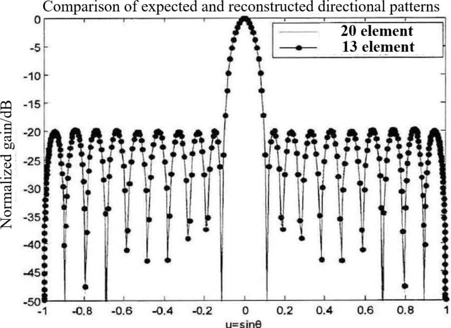
Figure 1: Alignment of expected and reconstructed directional graphs.
The number of sparse array units is necessary, which can reduce the cost. As shown in Fig. 1, it realizes the same characteristics as a full array with fewer units. In this paper, the scanning angle of the antenna array is different in azimuth and pitch direction. The azimuth needs to realize -45 to +45 degree scanning and the pitch needs to realize -30+30 degree scanning. If a rectangular grid is adopted, as shown in Fig. 2 (b), the final rectangle grid determined by antenna element spacing is dx= 0.014 m, dy=0.0156 m. The number of antenna elements required by the conventional rectangular raster antenna array is 230 and the spacing between elements is 0.5. The final number of units is determined to be 40 shown in Fig. 2 (c) and the dimensions are 300 mm 300 mm. The degree of sparsity reached 17% and the average inter-element spacing of the antenna is 0.2 when working in the low-frequency band. Considering the physical size of actual antenna elements, the minimum spacing between adjacent elements is 30 mm. Through the random array optimization algorithm, no grating lobes appear in the visible area when the antenna array is scanned in the area of azimuth plane 45 degrees and pitch plane 30 degrees. The convergence accuracy reaches the ratio of main and side lobes no less than the target value of 10 dB and the beam width no more than 35. Ideally, the scanning results of the designed sparse array at 12 GHz are shown in Fig. 3. It can be seen that the antenna can scan up to 45 degrees in the azimuth plane and 30 degrees in the pitching plane accurately.
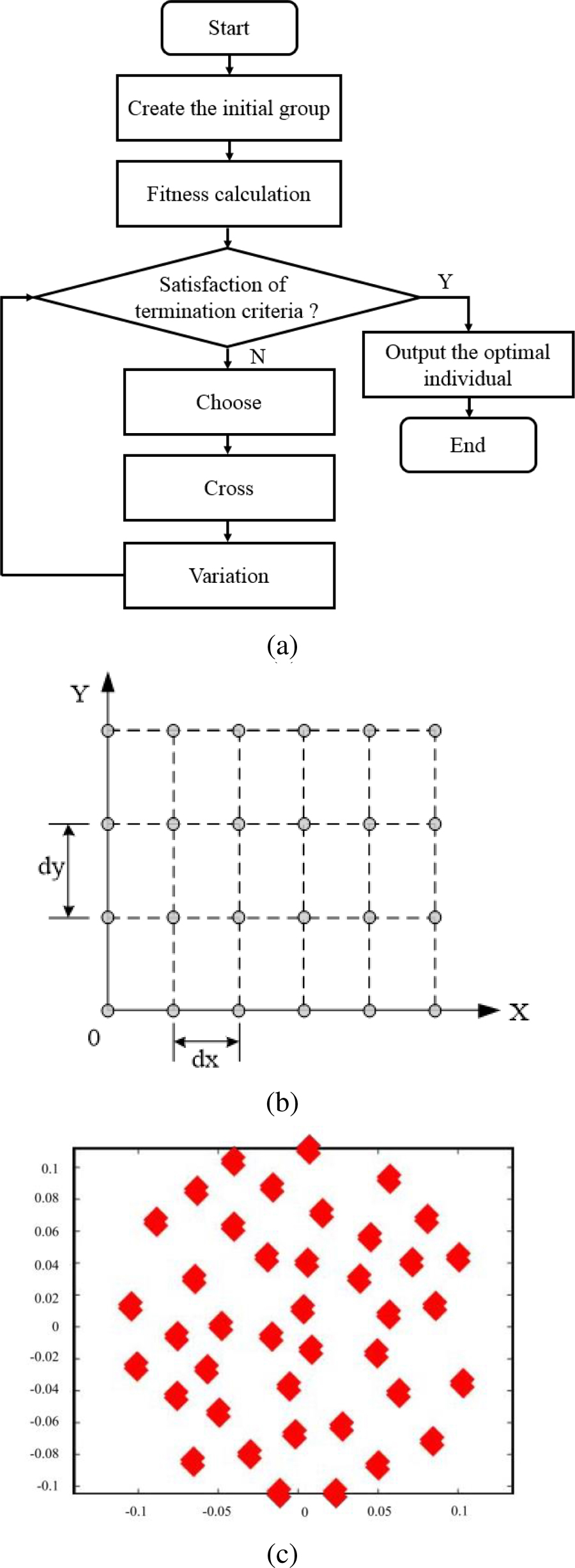
Figure 2: Sparse layout: (a) Flowchart of genetic algorithm. (b) Rectangular grid. (c) Sparse layout.
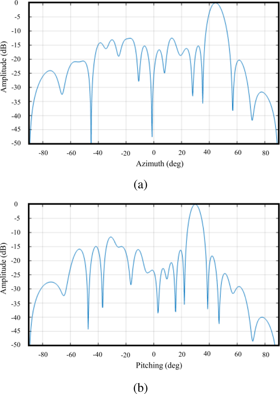
Figure 3: Scanning results: (a) Azimuth plane with scanning at 45 degrees. (b) Pitching plane with scanning at 30 degrees.
B. Design of the antenna unit
In the case that the theoretical design is finished, the next step is to verify whether the actual situation is realized. After the number and placement of array elements are determined, the structure of array elements needs to be designed. To put 40 antenna units in a finite aperture, a variety of UWB antennas are compared such as a corrugated horn, ridged horn, a helical antenna, and so on [15]. To meet the index requirements of a sparse array, various LPDA models are simulated in the design process.
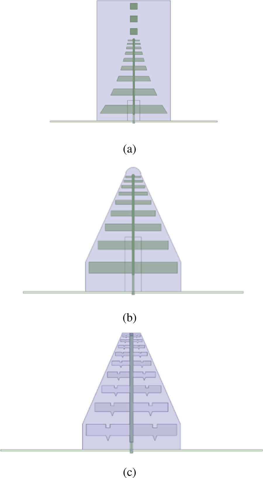
Figure 4: Schemes: (a) The contour shape of LPDA with a director. (b) LPDA with a dielectric lens. (c) LPDA of Koch fractal structure.
Figure 4 (a) shows the contour shape of LPDA with the director. The model can improve the antenna directivity greatly, but the impedance-matching effect is bad. Figure 4 (b) shows the LPDA with a dielectric lens. This structure is beneficial to improve the radiation efficiency of the antenna, but the cost of the lens is high. Figure 4 (c) shows the LPDA of the Koch fractal structure. Considering the performance of antenna elements and elements in the array, the printed LPDA isselected.
Figure 5 (a) shows the front view of improved LPDA, which is printed on a 1.016 mm dielectric substrate with a relative dielectric constant of 3.0 and a loss tangent of 0.002. To achieve miniaturization, unnecessary triangular areas are cut by the dielectric substrate. For traditional LPDA, the dimensions and spacing of each oscillator are determined by the same scale factor [16]:
| (3) |
where, and are the full length and width of the Mth symmetric bit. is the distance between the Mth symmetric bit and the Mth+1 bit. While keeping the length of the shortest and longest oscillator constant, the Vivaldi curve is adopted to cut the size of the remaining oscillators, which can not only reduce the transverse size to a certain extent but also improve the antenna gain in the operating frequency band [17]. The Vivaldi curve is expressed as follows:
| (4) |
| (5) |
| (6) |
where (y1, z1), (y2, z2) are the coordinates of starting and ending points of the curve respectively, and R is the gradient rate. The contour shape of LPDA can be changed by adjusting R. Here, we choose R to be 21.4.
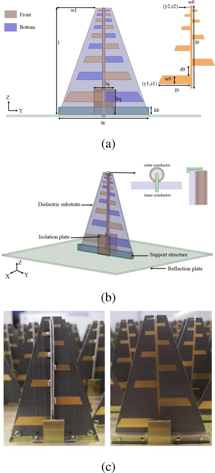
Figure 5: The structure of LPDA antenna element: (a) Front view. (b) 3D view. (c) Fabricated antenna.
Figure 5 (b) shows the overall structure of improved LPDA and the feeding structure in detail. A pair of metal isolation plates with a distance of 4 mm is added to the front and back sides of each antenna element to avoid serious coupling in the subsequent sparse array design. Considering the processing feasibility, a metal rectangular plate is added between the isolation plate and the printed dielectric plate as support. The antenna is fed by a coaxial cable, which passes through the reflection plate and feeds from the bottom [18]. The outer conductor is welded directly to the antenna. The dielectric between the inner and outer conductor is higher than the outer conductor. The feeding structure plays a role of a broadband unbalanced-to-balanced converter without affecting the radiation of the antenna, making it easier to achieve impedance matching. The fabricated antenna is shown in Fig. 5 (c). The final dimensions of the proposed LPDA are shown in Table 1.
Table 1: Dimensions of the Proposed Antenna Element (unit: mm)
| Symbol | Value | Symbol | Value |
|---|---|---|---|
| w | 56 | l9 | 24 |
| l | 64 | d9 | 7.5 |
| w0 | 1.2 | lq | 12 |
| l0 | 61 | hq | 16 |
| w1 | 23.4 | hb | 3 |
| w9 | 6 | 0.8 |
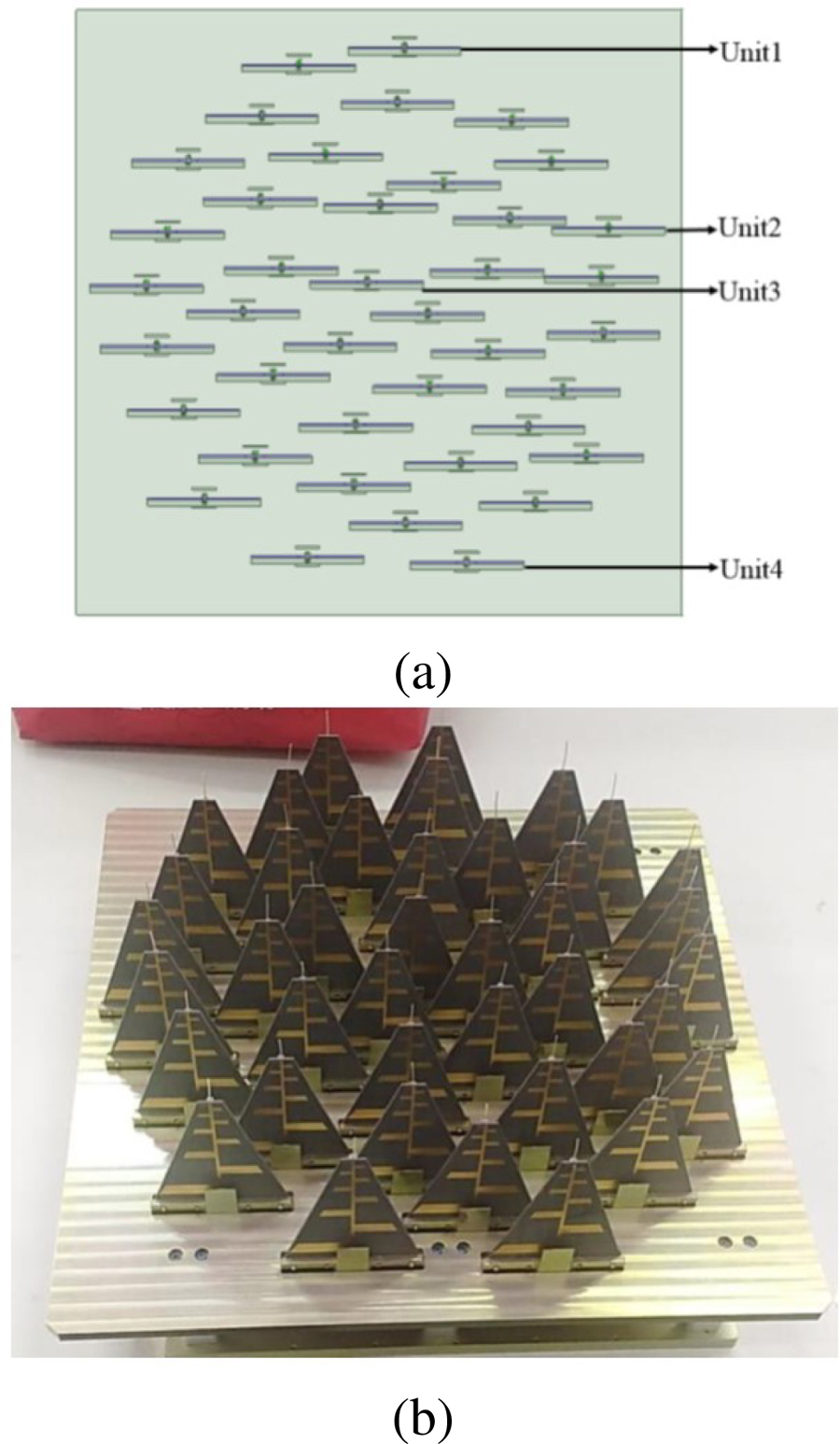
Figure 6: The sparse array model: (a) Simulated sparse array. (b) Fabricated sparse array.
C. Design of antenna array
After the unit design is completed, 40 antenna units are arranged according to the positions shown in Fig. 2. However, due to the idealization of the genetic algorithm, the position of some antenna elements needs to be further adjusted. The model of the sparse array after coordinate optimization is shown in Fig. 6.
III. SIMULATED AND MEASURED RESULTS
A. Active standing wave ratio results
The simulated active VSWR 3 bandwidth of the antenna is from 3 to 12 GHz (120%), as shown in Fig. 7. It can be seen that the active standing-wave ratio of individual units at individual frequency points exceeds 3. From Fig. 8, the results show the array antenna has a return loss of greater than 10 dB over an ultra-wide frequency band (approximately 5:1) for each unit. The operating frequency band of the array antenna is wider than that of the other antenna. However, when 40 units work simultaneously, individual units will not affect the array effect.

Figure 7: Active VSWR simulated results.
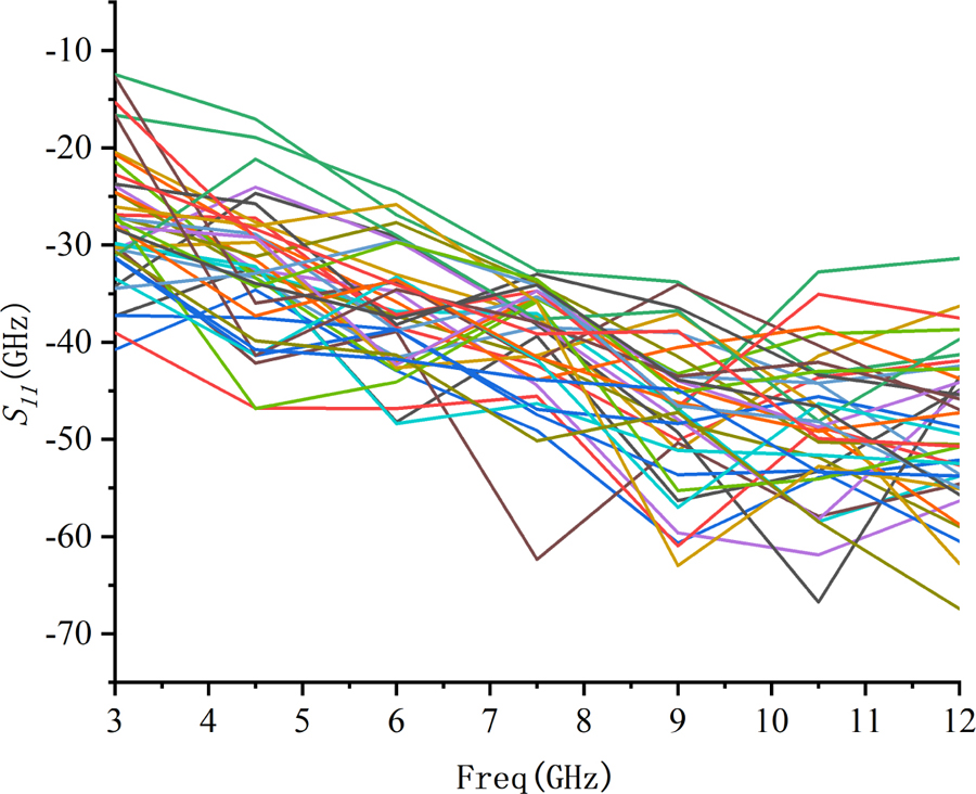
Figure 8: S Parameter results.
Active VSWR of some units in the array environment was measured by Popular Portable Phasor Network Analyzer (PNA) as Fig. 9 shows. Due to the limited space in this paper, feeding measured results of four ports mentioned in Fig. 6 are given in Fig. 10. It can be seen that the active standing wave ratio of the antenna units is less than 3.
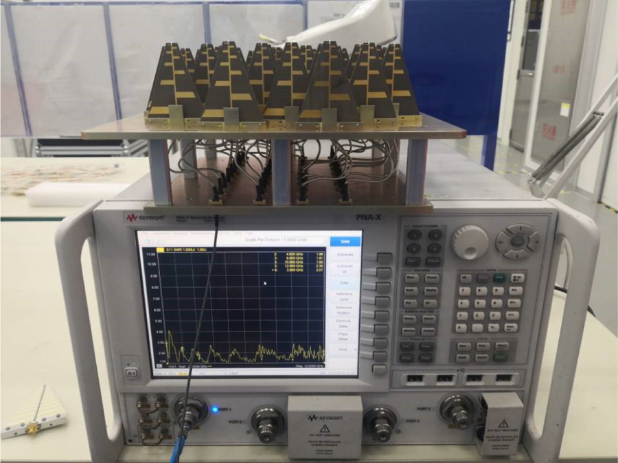
Figure 9: Active VSWR test environment.
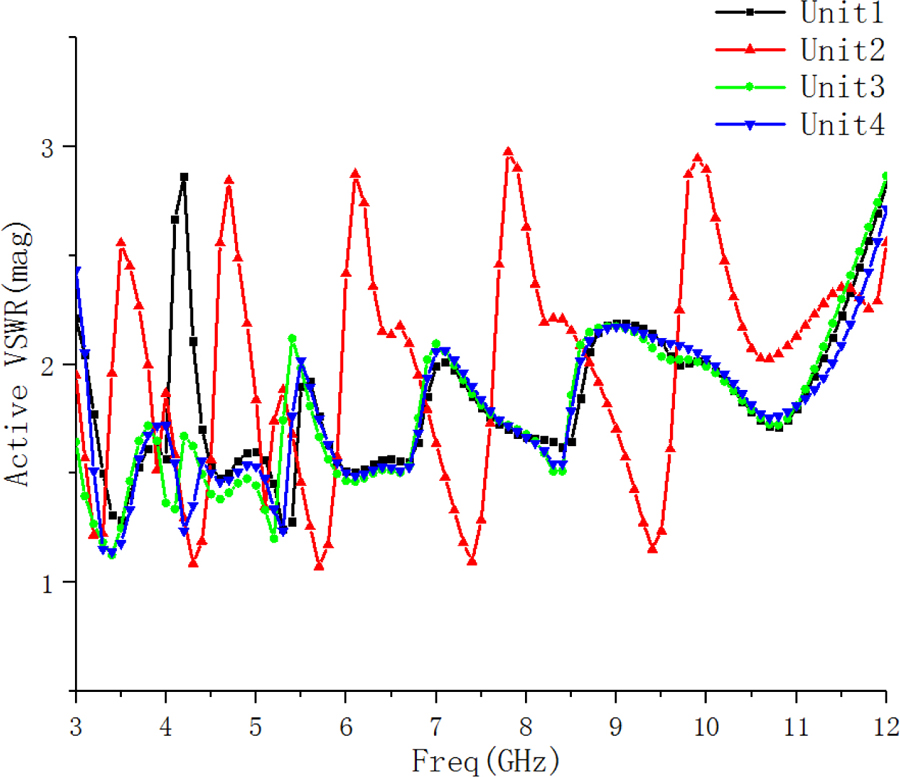
Figure 10: Active VSWR measured results.
B. Radiation pattern results
The radiation pattern was tested in the Microwave Anechoic Chamber using a planar near-field scanning technique as Fig. 11 shows. Figures 12 and 13 are the lobe diagrams at the azimuth plane with scanning 45 degrees and the pitching plane with scanning 30 degrees at 3.4 GHz, 6.5 GHz, and 11.5 GHz.
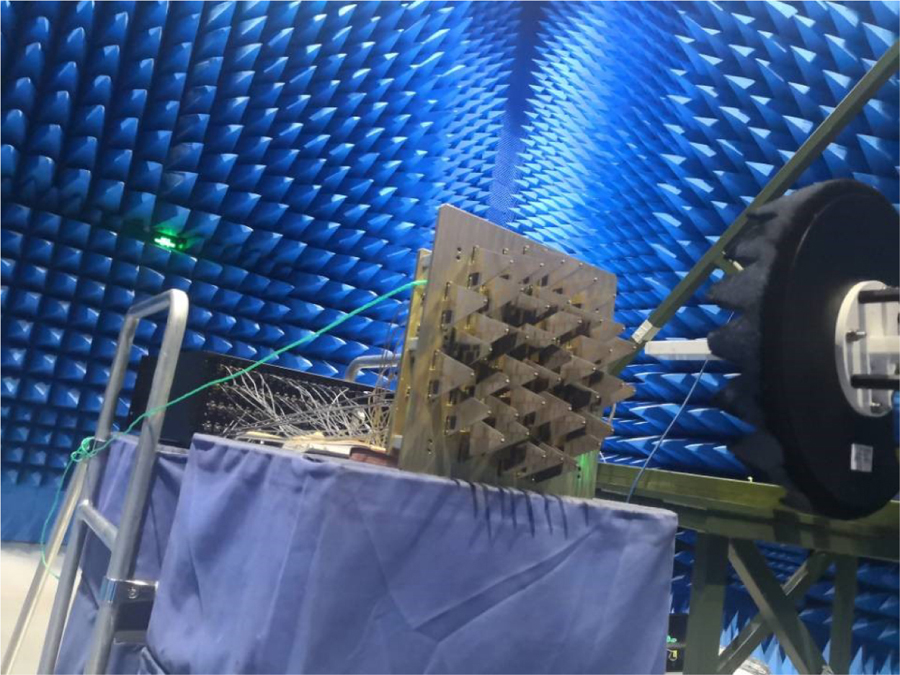
Figure 11: Radiation pattern test environment.
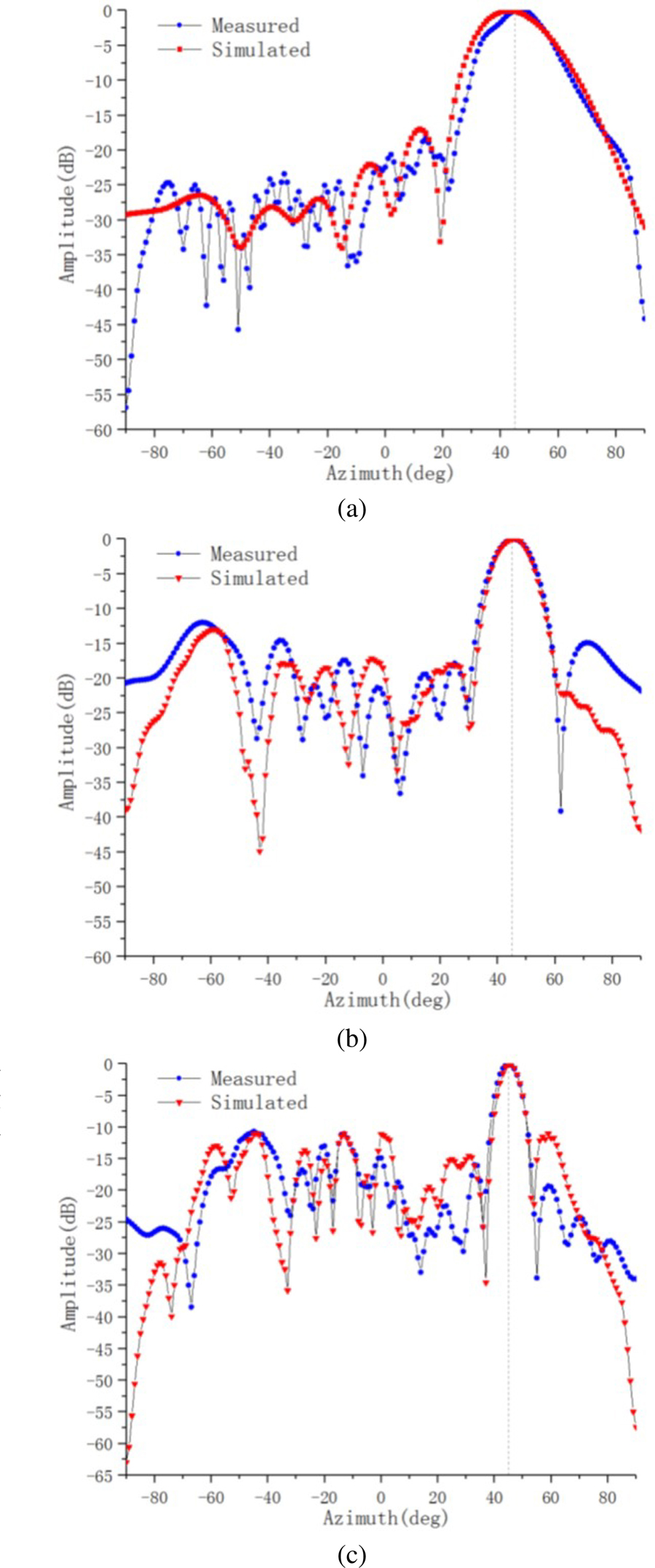
Figure 12: Radiation pattern in azimuth plane with scanning 45 degrees: (a) 3.4 GHz, (b) 6.5 GHz, (c) 11.5 GHz.
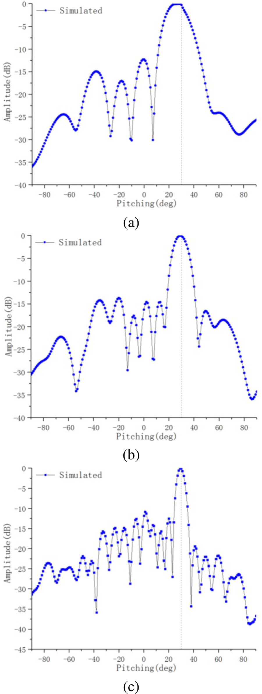
Figure 13: Radiation pattern in pitching plane with scanning 30 degrees: (a) 3.4 GHz, (b) 6.5 GHz, and (c) 11.5 GHz.
Table 2: Comparison with prior Literature
| Ref. | Units | BW | Scanning Angle |
|---|---|---|---|
| [11] | 256 | 3:1 | 45 |
| [12] | 64 | 5:1 | 45 |
| [13] | 64 | 3:1 | 60 |
| This Work | 40 | 5:1 | 45 |
Figure 14 shows the measured gain results. The gain of the proposed sparse array antenna is lower than that of the periodic array antenna with the same aperture. The decrease in gain is approximately proportional to the decrease in the number of active array elements, and the side-lobe is higher than that of the periodic array antenna with the same aperture. Therefore, when the gain and sidelobe requirement is not high, this sparse array can be used to achieve good performance with fewer antenna elements.
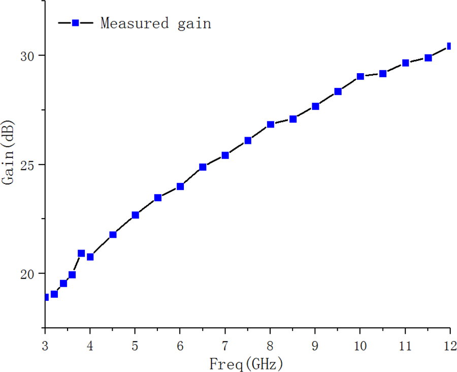
Figure 14: Measured and simulated gain.
IV. CONCLUSION
A new linearly polarized sparse array antenna with a small number of elements, well-controlled side-lobe levels, and wide-angle scanning is introduced. The sparse array is designed to replace the traditional periodic array to obtain better performance while reducing cost. The overall antenna has an impedance bandwidth of 120% for active VSWR 3. The measured result overlapped frequency band covers the range of 2.7 – 12 GHz. The simulation and measurement results indicate that the sparse array antenna can scan up to 45 in the azimuth plane, and up to 30 in the pitching plane. The demonstrated sparse array is a good candidate for popular S-band, C-band, and X-band applications, such as satellite communications.
ACKNOWLEDGMENT
We would like to thank the support of the open research fund of the National Mobile Communications Research Laboratory, Southeast University (No.2023D05), Anhui Natural Science Foundation (2208085MF161) Enterprise entrusted project (W2020JSKF0153, W2020JSFW0112), HeFei University of Technology teacher program (JZ2019HGTB0093).
REFERENCES
[1] K. Chen, Y. Li, and J. Shi, “Optimization of sparse concentric ring arrays for low sidelobe,” International Journal of Antennas and Propagation, vol. 2019, pp. 1485075, 2019.
[2] R. Z. Syeda, J. G. B. D. Vaate, and D. Prinsloo, “Regular and irregular-on-grid sparse array comparison of connected aperture arrays,” IEEE Antennas and Wireless Propagation Letters, vol. 19, no. 4, pp. 586-590, 2020.
[3] P. Rocca, G. Oliveri, R. J. Mailloux, and A. Massa, “Unconventional phased array architectures and design methodologies—A review,” Proceedings of the IEEE, vol. 104, no. 3, pp. 544-560,2016.
[4] K. Kayalvizhi, and S. Ramesh, “Design and analysis of reactive load dipole antenna using genetic algorithm optimization,” American Computational Electromagnetics Society (ACES) Journal, vol. 35, no. 3, pp. 279-287, 2020.
[5] J. Zolghadr, Y. Cai, and N. Ojaroudi, “UWB slot antenna with band-notched property with time domain modeling based on genetic algorithm optimization,” American Computational Electromagnetics Society (ACES) Journal, vol. 31, no. 8, pp. 926-932, 2016.
[6] H.-T. Chou, C.-W. Liu, H.-H. Chou, and W.-J. Liao, “Optimum horn antenna design based on an integration of HFSS commercial code and genetic algorithms for the feed application of reflector antennas,” American Computational Electromagnetics Society (ACES) Journal, vol. 25, no. 2, pp. 117-128, 2010.
[7] M. R. Stiglitz and C. Blanchard, Practical Phased-Array Antenna Systems, Artech House, Boston, USA, 1992.
[8] L. Xiaoming, and S. Xingrong, “Optimization design of sparse concentric ring arrays,” Tactical Missile Technology, vol. 3, 2017.
[9] H. Steyskal, J. K. Schindler, P. Franchi, and R. J. Mailloux, “Pattern synthesis for TechSat21 - a distributed space-based radar system,” IEEE Antennas and Propagation Magazine, vol. 45, no. 4, pp. 19-25, 2003.
[10] P. Bolli, et al., “Test-driven design of an active dual-polarized log-periodic antenna for the square kilometre array,” IEEE Open Journal of Antennas and Propagation, vol. 1, pp. 253-263, 2020.
[11] S. S. Holland and M. N. Vouvakis, “The Planar Ultrawideband Modular Antenna (PUMA) Array,” IEEE Transactions on Antennas and Propagation, vol. 60, no. 10, pp. 4589-4600, 2012.
[12] J. P. Doane, K. Sertel, and J. L. Volakis, “A wideband, wide scanning tightly coupled dipole array with integrated balun (TCDA-IB),” IEEE Transactions on Antennas & Propagation, vol. 61, no. 9, pp. 4538-4548, 2013.
[13] S. Xiao, S. Yang, H. Zhang, et al., “Practical implementation of wideband and wide-scanning cylindrically conformal phased array,” IEEE Transactions on Antennas and Propagation, vol. 99, pp. 1-1, 2019.
[14] M. F. Raji, H. Zhao, and H. N. Monday, “Fast optimization of sparse antenna array using numerical Green’s function and genetic algorithm,” International Journal Of Numerical Modelling: Electronic Networks, Devices and Fields, vol. 33, no. 4, pp. e2544, 2020.
[15] J. Jose, T. Mathew, A. Thomas, N. Haripriya, M. Cherian, and D. D. Krishna, “A cost effective hybrid-log periodic dipole antenna (H-LPDA),” 2015 Fifth International Conference on Advances in Computing and Communications (ICACC), pp. 263-265, 2015.
[16] Z. Wang, X. Zhao, F. Ji, S. Huang, and Z. Jiang, “Ultra-wideband cylindrical conformal array antenna based on LPKDA,” 2020 IEEE MTT-S International Conference on Numerical Electromagnetic and Multiphysics Modeling and Optimization (NEMO), pp. 1-4, 2020.
[17] Y. Hu, “Study on novel printed log periodic antennas,” Nanjing University of Posts and Telecommunications, Nanjing, China, 2018.
[18] J. Fang, M. Jin, and X. Zhang, “An UWB printed log-periodic array antenna,” 2018 International Workshop on Antenna Technology (iWAT), pp. 1-3, 2018.
BIOGRAPHIES

Z. N. Jiang was born in Xuancheng, China. He received the Ph.D. degree from Nangjing University of Science And Technology, Nanjing, China, in 2012. Since 2013, he has worked on the numerical method of computational electromagnetism. He is currently a Professor with the Hefei University of Technology, Hefei, China. He has authored or coauthored more than 90 papers in refereed international conferences and journals and has served as Program Committee Member in several international conferences. Currently, he is focusing on antenna and microwave device. (Email: jiangzhaoneng@hfut.edu.cn)

Y. Zheng was born in Anhui, China, in 1998. He is currently working towards the M.E degree in Electronic Science & Applied Physics from Hefei University of Technology. He is currently focusing on antenna and microwave device design. (Email: 1597021984@qq.com)

X. F. Xuan was born in Anhui, China, in 1975. He received the M.S. degree from Nanjing University, China. He is focusing on numerical method of computational electromagnetism. (Email:941067868@qq.com)

N. Y. Nie (corresponding author) was born in Shandong, China, in 1990. She received the Ph.D. degree from University of Electronic Science and Technology of China. She is focusing on theory and design of microwave and millimeter wave antenna.(Email: liyingnie@sina.com)
ACES JOURNAL, Vol. 38, No. 2, 100–108
doi: 10.13052/2023.ACES.J.380204
© 2023 River Publishers