Wideband Single-Fed Circularly Polarized Stacked Patch Antenna With L-Shaped Stub
Wen Li, Wei Xue, Yingsong Li, Xiang Xiong, Kwok L. Chung, and Zhixiang Huang
1College of Information and Communication Engineering
Harbin Engineering University, Harbin, 150001, China
2The Key Laboratory of Intelligent Computing and Signal Processing, Ministry of Education
Anhui University, Hefei, Anhui, 230000, China
liyingsong@ieee.org
3School of Computing Science and Engineering
Huizhou University, Huizhou, 516007, China
Submitted On: October 27, 2022; Accepted On: December 4, 2022
ABSTRACT
A wideband single-fed circularly polarized (CP) stacked patch antenna with an L-shaped stub is presented. The CP antenna is made up of the bottom gradient microstrip transmission line, middle driven patch and top square radiation patch. The driven patch with an L-shaped stub and opening slot can achieve a wideband CP radiation which is different from a conventional patch. The presented CP stacked patch antenna maintains good directional radiation, while featuring wideband CP radiation. The final tested results indicate that the presented CP antenna has significant performance with a 10-dB impedance bandwidth of 42.1% (4.26-6.53 GHz), a 3-dB AR bandwidth of 26.0% (4.36-5.66 GHz) and broadside peak gain of 8.6 dBic. Moreover, the fifth-generation (5G) N79 band (4.4-5.0 GHz) and 5G wireless local area network (WLAN) band (5.15-5.35 GHz) can be covered by the operating bandwidth of the presented CPantenna.
Index Terms: circularly polarized (CP), L-shaped stub, patch antenna, wideband antenna.
I. INTRODUCTION
Circularly polarized (CP) stacked patch antenna have urgent application in modern wireless communication systems [1–3]. CP patch antennas, which are characterized by their compactness, ease of fabrication and resistance to multipath fading, have become the common schemes [4]. But the single-layer CP patch antenna has a high Q factor, which cannot meet the requirements of broadband. So, the study of the wideband CP patch antenna is an important topic.
Using parasitic patches in CP patch antenna is promising and is a common method to expand the axial ratio (AR) bandwidth [5–7]. In [5], the CP patch antenna with capacitively coupled feed and rotated four parasitic strips achieve a wide AR bandwidth. In [6], the antenna composed of eight parasitic patches and feeding loop, which are placed on the same plane, is presented to yield a wide AR bandwidth. Compared with complete ground plane in [6], the ground plane with four crown slots in [7] is utilized to further expand AR bandwidth. Using stacked patches on radiation patches can also widen the AR bandwidth[8–13]. There are different shaped stacked patches, such as notched circular patch [8], hexagonal microstrip patch [9] and square patch [10], which realize 3-dB AR bandwidth of 10%, 13% and 11%. In [11], this CP antenna is fed by a corner-truncated ring, which can simplify the feeder structure. The CP patch antenna in [12] contains a stacked patch with pin-load, which can realize high gain. In addition to the above methods, many single-fed broadband CP antennas have recently been proposed [14–23]. In [14, 15], the L-shaped probe is employed to couple the patch and realize wide AR bandwidth. The near-field resonant parasitic CP patch antenna for radio frequency identification (RFID) reader applications yields an AR bandwidth of 9% [16]. In [17], three-dimensional split-ring resonators are used to achieve compact wideband CP antenna for fifth-generation (5G) new radio applications.
Multi-fed is command method to expand the AR bandwidth [24–33]. In [24], the single circular patch excited by dual capacitively coupled feeds with phase shift features a wide AR bandwidth of 35%. This CP antenna array in [25], which has three centrosymmetric phase shift feeds, can realize broadband CP radiation. A novel CP antenna consisting of four probes and parasitic patches is designed for the global positioning system [26]. Typically, four-port feed CP antenna array consists of four sequential rotation antenna elements and four-port power divider, which provide the phases of , , , . In [27], a wideband Wang-shaped CP patch antenna array, which has unidirectional radiation, is introduced and final measured results show AR bandwidth. As mentioned above, multi-feed antenna array can realize the advantages of high gain while maintaining wideband AR bandwidth and unidirectional radiation, but the antenna array requires complicated feed network, which reduces the final efficiency [34].
In this article, a wideband CP stacked patch antenna is introduced. For achieving the circular polarization, the opening slot and L-shaped stub are adopted to the conventional stacked patch antenna. In the final design, the proposed CP antenna has good directional radiation with front-to-back ratio of 23.48 dB at 5 GHz, while featuring wide AR bandwidth. The final tested results indicate that the final CP antenna has significant performances with a 10-dB impedance bandwidth of 42.1% (4.26-6.53 GHz), a 3-dB AR bandwidth of 26.0% (4.36-5.66 GHz) and peak broadside gain of 8.6 dBic. Moreover, the measured AR bandwidth, which achieved good agreement with simulation results, can cover 4.4-5.0 GHz of the 5G N79 band and 5.15-5.35 GHz band of 5G WLAN at the same time, which can be utilized for different applications.
II. ANTENNA DESIGN AND PERFORMANCE
A. Antenna geometry
As shown in Fig. 1, four-layer dielectric substrates are adopted to fabricate the proposed wideband single-fed CP patch antenna. Three different substrates are adopted, in which Layer_1 and Layer_3 have a dielectric permittivity 3, a loss tan of 0.0027, and a thickness h1 of 1 mm, Layer_2 for the driven patch has a dielectric permittivity of 3.5, a loss tan of 0.0027, and a thickness h3 of 1.5 mm, Layer_4 for the ground plane and feeding line has a dielectric permittivity of 4.4, a loss tan of 0.025 and a thickness h4 of 0.8 mm. Figure 1 (a) shows the radiation patch on the top of Layer_1. The driven patch consists of rectangular patch with opening slot and L-shaped stub on the Layer_2, which provides the CP mode. Figure 1 (b) shows the air gap between Layer_1 and Layer_2 with a thickness of 4 mm. The gradient feeding line, which provides the good impedance matching, is fabricated on the bottom of Layer_4. This antenna was optimized by CST microwave software. The optimized antenna parameters are: Lg = 60, W1 = 17, W2 = 17, W3 =0.2, W4 = 2.0, Slotw = 6, Cpw = 7, d = 1.2, r = 1, L1 = 3, G1 = 6, G2 = 3, s = 1, W5 = 3, W6 = 1.5, L2 = 8, L3 = 8. Unit: mm.

Figure 1: Structure of the presented CP antenna. (a) three-dimensional view. (b) Side view. (c) Top view of Layer_1. (d) Top view of Layer_2. (e) Top view of Layer_4. (f) Bottom view of Layer_4.
B. Design process
With reference to Fig. 2, three prototypes are given for exploring the mechanism of wideband CP, which have the same radiation patch. Ant. 1 is the conventional stacked patch antenna, which enables wide impedanc bandwidth and high gain. Some researchers have proposed high-gain filtering antenna [35], ultra-wideband microstrip patch antenna [36] and wideband CP antenna [10] based on this stacked patch antenna. The L-shaped stub is employed to realize the circular polarization in Ant. 2. The open slot is added to Ant. 3 when compared with Ant. 2. The same substrate type and height is used in all three antennas.
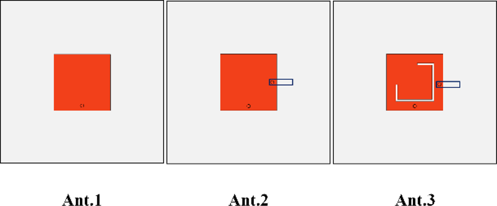
Figure 2: Evolution of the presented antenna.
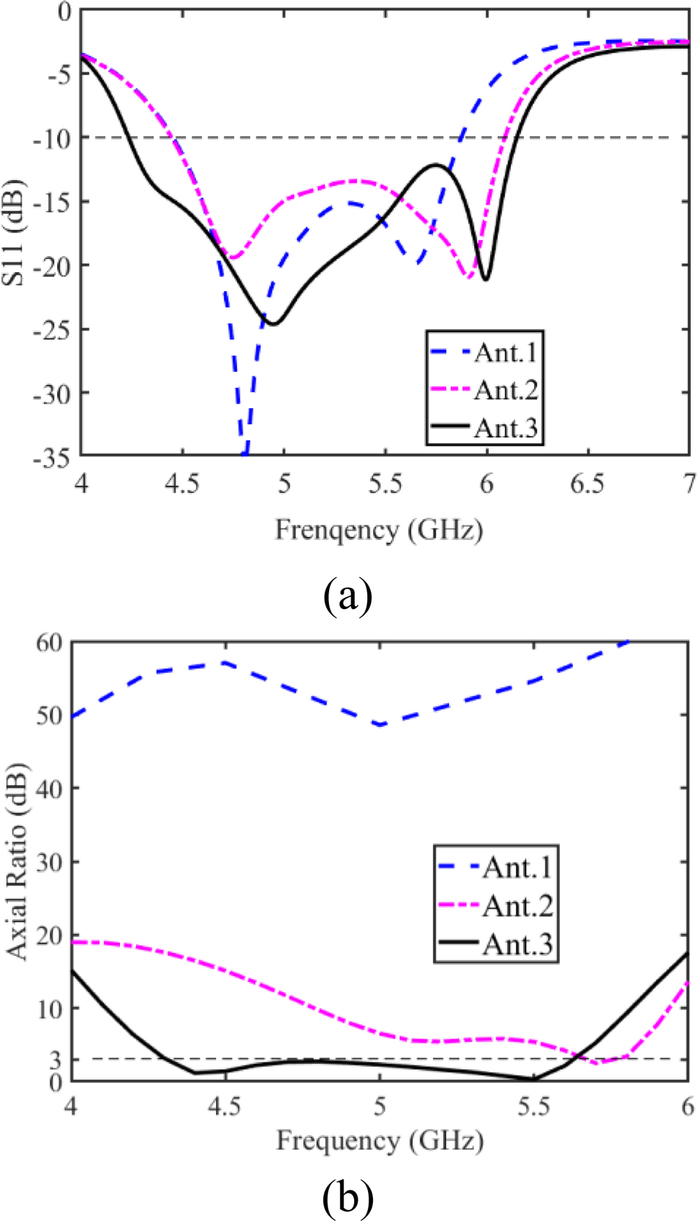
Figure 3: Simulated results of the presented antenna in different antennas. (a) Reflection coefficient and (b) AR.
The driven patch is fed by a probe and has the same width of 17 mm as the radiation patch. With reference to Fig. 3, the Ant. 1 has two resonances near to 4.8 and 5.6 GHz and achieves linear polarization. For improving the CP performance, the L-shaped stub is utilized in Ant. 2. In Fig. 3, the resonance frequency at high frequency moves from 5.6 to 6 GHz, the AR of Ant. 2 is below 20 at 4 to 6 GHz and especially below 3 at 5.7 GHz. It is noteworthy that the CP radiation of the original stacked patch antenna is apparently improved because of the L-shaped stub structure, but the 3-dB AR bandwidth is narrow. As shown in Fig. 2, the opening slot, which can extend the AR bandwidth, is etched on the driven patch in Ant. 3. It is obvious that the AR of Ant. 3 decreases compared to Ant. 2. In Fig. 3, the Ant. 3 has a simulated 3-dB AR bandwidth of 27% (4.29-5.63 GHz) and 10-dB impedance bandwidth of 37% (4.23–6.15 GHz).
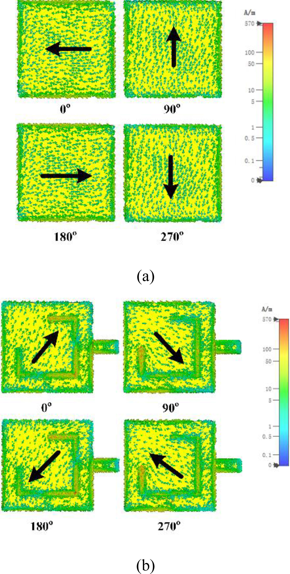
Figure 4: Surface current distributions on the radiation patch and driven patch of the proposed antenna at 5 GHz in , , , and phase. (a) Radiation patch and (b) Driven patch.
Figure 4 shows the simulated surface current contributions at 5 GHz, which can achieve the verification of circularly polarized radiation. In Fig. 4, the surface current contributions of the square radiation patch and driven patch with L-shaped stub and opening slot are provided. In Fig. 4 (a), the current of the radiation patch flows in the direction of the black arrow at the phase of , whereas the current rotates in a clockwise direction at the phase of . The direction of the surface current in the driven patch is different from the direction of the radiation because the radiation patch is fed by a driven patch coupling. It is found that the direction of surface current, which is represented by the black arrow, is clockwise with a phase change. The left-hand CP radiation is produced based on the direction of current rotation.
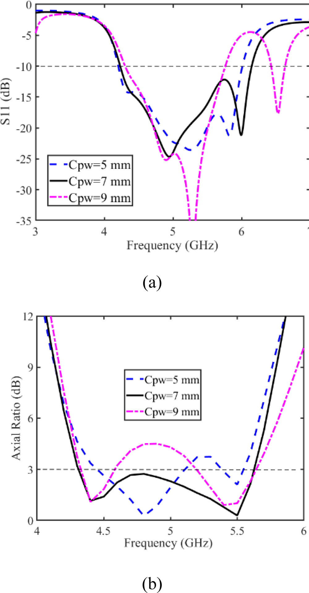
Figure 5: Effect of the L-shaped stub length Cpw of driven patch on (a) reflection coefficient and (b) AR.
Parametric studies are implemented for determining the final dimensions. The proposed antenna performance including the reflection coefficient and AR is influenced by the numerous parameters. Here, two key parameters Cpw (the L-shaped stub length) and Slotw (the opening slot length) have been selected for study. Figure 5 demonstrates the effect of the L-shaped stub Cpw on the reflection coefficient and AR. Two resonant frequency points are generated on the reflection coefficient curve and two minimum points in the AR curve. The high resonant frequency shifts to higher frequencies as Cpw increases, but when Cpw equals 9 mm the reflection coefficient of 5.46 to 5.92 GHz between the two resonance points is higher than 10 dB in Fig. 5 (a). AR is significantly influenced by Cpw and a 3-dB AR bandwidth of 27% is exhibited, when Cpw equals 7 mm. Figure 6 demonstrates the influence of the opening slot length Slotw on reflection coefficient and AR. It is found that the resonance frequencies change significantly and the minimum value of AR decreases and then rises with Slotw increasing from 4 to 8 mm. So, a Slotw value of 6 mm is chosen as the final dimension.
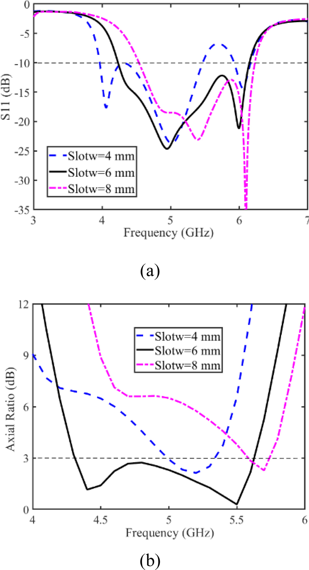
Figure 6: Effect of the opening slot length Slotw of driven patch on (a) reflection coefficient and (b) AR.
III. EXPERIMENTAL VERIFICATION
The prototype has been fabricated for achieving validation of the presented antenna. Agilent N5062A Network Analyzer was adopted to measure the reflection coefficient. With reference to Fig. 7, an anechoic chamber was utilized to test the radiation characteristics including the gains and ARs. Figure 8 demonstrates the simulated and measured results including reflection coefficient, AR, and gain. A 10-dB simulated impedance bandwidth of 37.0% (4.23-6.15 GHz) is obtained, while the measured impedance bandwidth is 42.1% (4.26-6.53 GHz). A 3-dB simulated AR bandwidth is 26.0% covering 4.36 to 5.66 GHz. The measured broadside gain at 5 GHz is 8.6 dBic and the measured gain is a little lower than the simulated gain from 4 to 6 GHz. This is because substrate material suffers from instability in dielectric constant and loss.

Figure 7: (a) Photograph of the fabricated prototype. (b) Photograph of anechoic chamber testing.
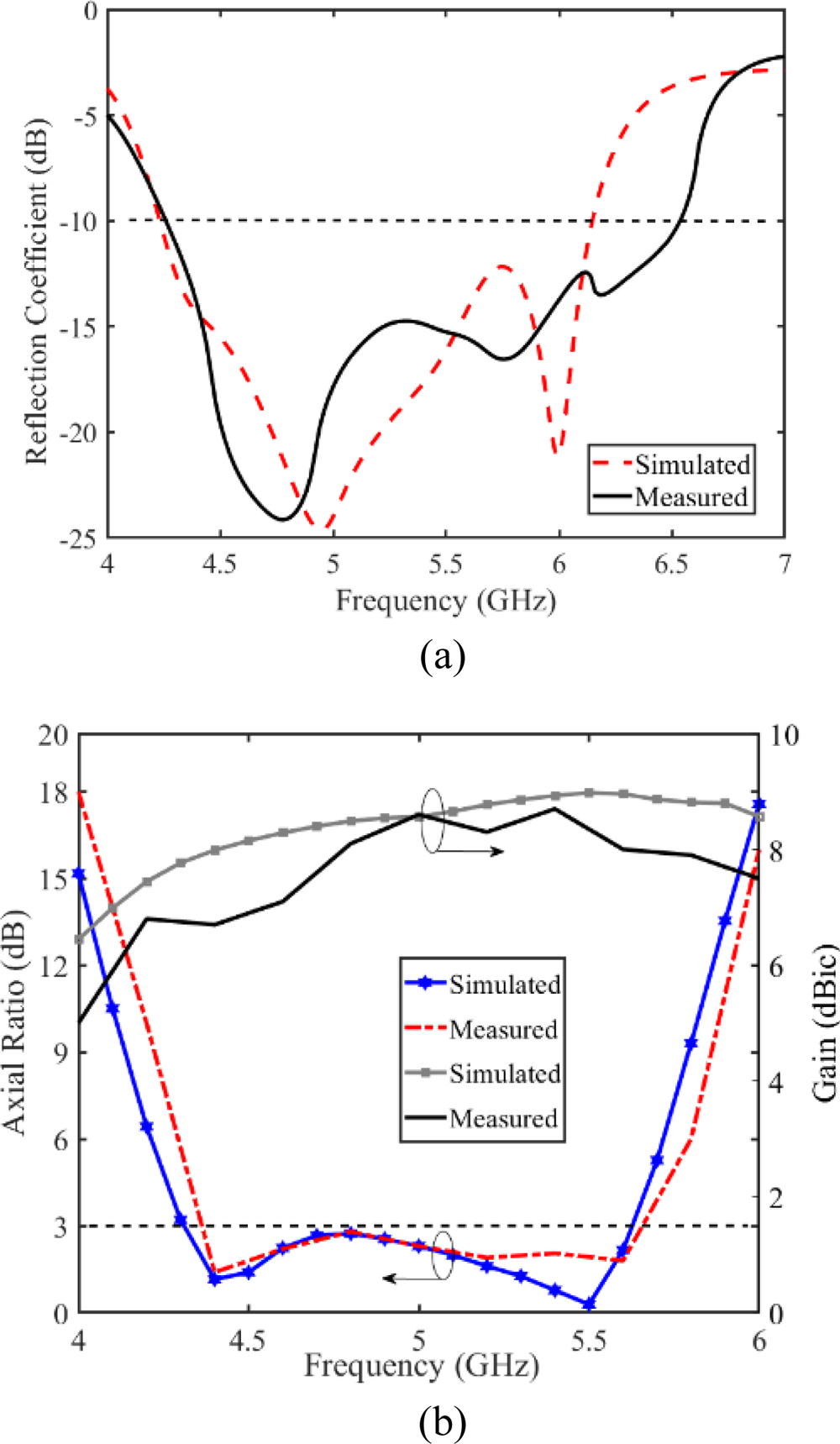
Figure 8: Simulated and measured results of the presented CP patch antenna. (a) Reflection coefficient. (b) AR and peak gain.
Table 1: Comparison to the performance of other CP antennas
| References | Size () | Freq (GHz) | 10-dB Impedance Bandwidth (%) | 3-dB AR Bandwidth (%) | Peak Gain (dBic) |
|---|---|---|---|---|---|
| Ref. [6] | 0.920.920.028 | 5.136.24 | 19.5 | 12.9 | 9.8 |
| Ref. [7] | 1.021.020.028 | 5.206.40 | 25.9 | 20.6 | 8.0 |
| Ref. [8] | //0.15 | 3.36.4 | 63.9 | 10.0 | 8.0 |
| Ref. [11] | 0.650.650.066 | 3.66.0 | 20.6 | 6.9 | 7.0 |
| Ref. [13] | 0.80.80.09 | 2.082.62 | 22.9 | 17.9 | 8.5 |
| Ref. [16] | 0.450.450.074 | 0.830.96 | 32.4 | 9.0 | 7.3 |
| Ref. [17] | 0.2770.2770.03 | 3.33.8 | 14.1 | 14.2 | 5.1 |
| Proposed design | 110.122 | 4.266.53 | 42.1 | 26.0 | 8.6 |
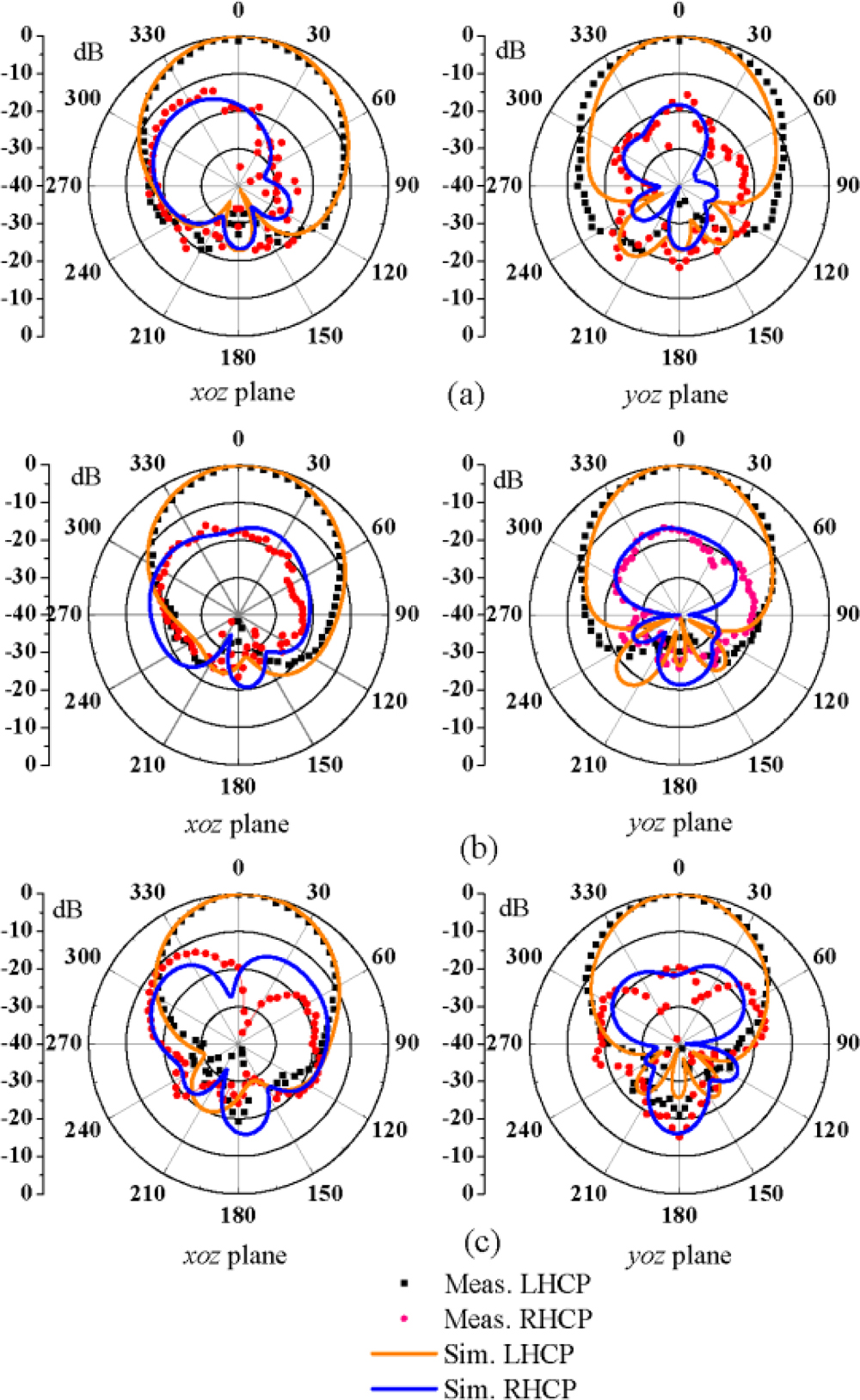
Figure 9: Simulated and measured radiation patterns of the final tested antenna. (a) At 4.5 GHz, (b) at 5 GHz, (c) at 5.5 GHz.
Figure 9 demonstrates the normalized radiation patterns at the significant frequencies of 4.5, 5, and 5.5 GHz. The normalized left-hand CP has a value of 0 dB, which is clearly greater than the normalized right-hand CP in z-axis direction. The measured radiation patterns maintain a high degree of similarity to the simulated patterns. The proposed antenna records half-power beamwidths of and in the two principal planes, and a front-to-back ratio of 23.48 dB.
IV. PERFORMANCE COMPARISON
Table 1 illustrates a comparison of various parameters including numerous key parameters. The compact CP patch antenna in [6] with feeding loop produced a high gain of about 9.8 dBic, but have the narrow AR bandwidth of 12.9. Incomplete ground plane is utilized in [7] to expand the AR bandwidth but the radiation of this CP patch antenna is non-directional radiation. In [8, 11, 16] and [17], the peak gain of the antennas is lower than 8 dBic. The antenna in [13] with a horizontal L-shaped strip exhibits the peak gain of 8.5 dBic and a 3-dB AR bandwidth of 17.9%. The proposed CP stacked patch antenna with an L-shaped stub produces a wide operation bandwidth 26% (4.36-5.66 GHz) and a high broadside gain of 8.6 dBic.
V. CONCLUSION
A wideband CP patch antenna with an L-shaped stub is presented. Based on conventional stacked antenna, the opening slot and L-shaped stub are added to expand the AR bandwidth. The effect of length of the L-shaped stub and the opening slot on the reflection coefficient and AR is studied. The final measured results exhibit a 10-dB impedance bandwidth of 42.1% (4.26-6.53 GHz), a 3-dB AR bandwidth of 26% (4.36-5.66 GHz) and a peak broadside gain of 8.6 dBic. This wideband CP patch antenna has significant directional radiation with front-to-back ratio of 23.48 dB at 5 GHz. Owing to the advantage of broadband CP radiation and high gain, the presented CP patch antennas have a wide range of 5Gapplications.
REFERENCES
[1] F. Zhu, Q. Luo, and S. Gao, Circularly Polarized Antennas, Wiley, New York, USA, 2013.
[2] N. Yan, K. Ma, and Y. Luo, “An SISL sequentially rotated feeding circularly polarized stacked patch antenna array,” IEEE Transactions on Antennas and Propagation, vol. 68, no. 3, pp. 2060-2067, 2020.
[3] B. Feng, L. Li, K. L. Chung, and Y. Li, “Wideband widebeam dual circularly polarized magnetoelectric dipole antenna/array with meta-columns loading for 5G and beyond,” IEEE Transactions on Antennas and Propagation, vol. 69, no. 1, pp. 219-228, 2021.
[4] K. L. Wong, Compact and Broadband Microstrip Antennas, Wiley, New York, USA, 2002.
[5] J. Wu, Y. Yin, Z. Wang, and R. Lian, “Broadband circularly polarized patch antenna with parasitic strips,” IEEE Antennas and Wireless Propagation Letters, vol. 14, pp. 559-562, 2015.
[6] K. Ding, C. Gao, D. Qu, and Q. Yin, “Compact broadband circularly polarized antenna with parasitic patches,” IEEE Transactions on Antennas and Propagation, vol. 65, no. 9, pp. 4854-4857,2017.
[7] L. Wang, Z. Zhu, and Y. En, “Performance enhancement of broadband circularly polarized slot-microstrip antenna using parasitic elements,” IEEE Antennas and Wireless Propagation Letters, vol. 20, no. 12, pp. 2255-2259, 2021.
[8] Y. Guo and D. C. H. Tan, “Wideband single-feed circularly polarized patch antenna with conical radiation pattern,” IEEE Antennas and Wireless Propagation Letters, vol. 8, pp. 924-926, 2009.
[9] N. Nasimuddin, X. Qing, and Z. N. Chen, “A wideband circularly polarized stacked slotted microstrip patch antenna,” IEEE Antennas and Propagation Magazine, vol. 55, no. 6, pp. 84-99, 2013.
[10] T. Mondal, S. Samanta, R. Ghatak, and S. R. B. Chaudhuri, “A novel hexagonal wideband circularly polarized stacked patch microstrip antenna,” Microw. Opt. Technol. Lett., vol. 57, no. 11, pp. 2548-2554, 2015.
[11] C. Deng, X. Lv, and Z. Feng, “Low-profile circularly polarised patch-ring antenna with compact feeding network,” IET Microwaves Antennas & Propagation, vol. 12, no. 3, pp. 410-415,2017.
[12] Z.-X. Liu, L. Zhu, and X. Zhang, “A low-profile and high-gain CP patch antenna with improved AR bandwidth via perturbed ring resonator,” IEEE Antennas and Wireless Propagation Letters, vol. 18, no. 2, pp. 397-401, 2019.
[13] J. Wu, X. Ren, Z. Wang, and Y. Yin, “Broadband circularly polarized antenna with L-shaped strip feeding and shorting-pin loading,” IEEE Antennas and Wireless Propagation Letters, vol. 13, pp. 1733-1736, 2014.
[14] K. L. Chung, A. Cui, and B. Feng, “A Guo-shaped patch antenna for hidden WLAN access points,” International Journal of RF and Microwave Computer-Aided Engineering, vol. 31, no. 2, 2021.
[15] W. K. Lo, J. L. Hu, C. H. Chan, and K. M. Luk, “Circularly polarized patch antenna with an L-shaped probe fed by a microstrip line,” Microwave and Optical Technology Letters, vol. 24, no, 6, pp. 412-414, 1999.
[16] J. Li, H. Liu, S. Zhang, M. Luo, Y. Zhang, and S. He, “A wideband single-fed, circularly-polarized patch antenna with enhanced axial ratio bandwidth for UHF RFID reader applications,” IEEE Access, vol. 6, pp. 55883-55892, 2018.
[17] Z. Wang, Y. Dong, and T. Itoh, “Miniaturized wideband CP antenna based on metaresonator and CRLH-TLs for 5G new radio applications,” IEEE Transactions on Antennas and Propagation, vol. 69, no. 1, pp. 74-83, 2021.
[18] K. L. Chung, “A wideband circularly polarized H-shaped patch antenna,” IEEE Transactions on Antennas and Propagation, vol. 58, no. 10, pp. 3379-3383, 2010.
[19] H. L. Zhu, S. W. Cheung, K. L. Chung, and T. I. Yuk, “Linear-to-circular polarization conversion using metasurface,” IEEE Transactions on Antennas and Propagation, vol. 61, no. 9, pp. 4615-4623, 2013.
[20] K. L. Chung, S. Xie, Y. Li, R. Liu, S. Ji, and C. Zhang, “A circular-polarization reconfigurable Meng-shaped patch antenna,” IEEE Access, vol. 6, pp. 51419-51428, 2018.
[21] B. Feng, L. Li, K. L. Chung, and Y. Li, “Wideband widebeam dual circularly polarized magnetoelectric dipole antenna/array with meta-columns loading for 5G and beyond,” IEEE Transactions on Antennas and Propagation, vol. 69, no. 1, pp. 219-228, 2021.
[22] Y. Li and R. Mittra, “A three-dimensional circularly polarized antenna with a low profile and a wide 3-dB beamwidth,” Journal of Electromagnetic Waves and Applications, vol. 30, no. 1, pp. 89-97, 2016.
[23] B. Qiu and Y. Li, “Gain-enhanced wideband circularly polarized antenna with a non-uniform metamaterial reflector,” Applied Computational Electromagnetics Society (ACES) Journal, vol. 37, no. 3, pp. 281-286, 2022.
[24] K.-L. Wong and T.-W. Chiou, “Broad-band single-patch circularly polarized microstrip antenna with dual capacitively coupled feeds,” IEEE Transactions on Antennas and Propagation, vol. 49, no. 1, pp. 41-44, 2001.
[25] C. Lin, F. Zhang, Y. Jiao, F. Zhang, and X. Xue, “A three-fed microstrip antenna for wideband circular polarization,” IEEE Antennas and Wireless Propagation Letters, vol. 9, pp. 359-362, 2010.
[26] S. Fu, Q. Kong, S. Fang, and Z. Wang, “Broadband circularly polarized microstrip antenna with coplanar parasitic ring slot patch for L-band satellite system application,” IEEE Antennas and Wireless Propagation Letters, vol. 13, pp. 943-946,2014.
[27] K. L. Chung, Y. Li, and C. Zhang, “Broadband artistic antenna array composed of circularly-polarized Wang-shaped patch elements,” AEU-International Journal of Electronics and Communications, vol. 74, pp. 116-122, 2017.
[28] K. L. Chung, W. Li, Y. Li, R. Liu, and P. Zhang, “Chinese character-shaped artistic patch antenna,” IEEE Antennas and Wireless Propagation Letters, vol. 18, no. 8, pp. 1542-1546, 2019.
[29] K. L. Chung, X. Yan, A. Cui, and Y. Li, “Circularly-polarized linear antenna array of non-identical radiating patch elements for WiFi/WLAN applications,” AEU-International Journal of Electronics and Communications, vol. 129, 2020.
[30] K. L. Chung and A. S. Mohan, “A circularly polarized stacked electromagnetically coupled patch antenna,” IEEE Transactions on Antennas and Propagation, vol. 52, no. 5, pp. 1365-1369, 2004.
[31] K. L. Chung, “High-performance circularly polarized antenna array using metamaterial-line based feed network,” IEEE Transactions on Antennas and Propagation, vol. 61, no. 12, pp. 6233-6237,2013.
[32] K. L. Chung and S. Kharkovsky, “Mutual coupling reduction and gain enhancement using angular offset elements in circularly polarized patch array,” IEEE Antennas and Wireless Propagation Letters, vol. 12, pp. 1122-1124, 2013.
[33] B. Liu, X. Chen, J. Tang, A. Zhang, and A. A. Kishk, “Co- and cross-polarization decoupling structure with polarization rotation property between linearly polarized dipole antennas with application to decoupling of circularly polarized antennas,” IEEE Transactions on Antennas and Propagation, vol. 70, no. 1, pp. 702-707, 2022.
[34] X. Chen, M. Zhao, H. Huang, Y. Wang, S. Zhu, C. Zhang, J. Yi, and A. Kishk, “Simultaneous decoupling and decorrelation scheme of MIMO arrays,” IEEE Transactions on Vehicular Technology, vol. 71, no. 2, pp. 2164-2169, 2022.
[35] X. Y. Zhang, W. Duan, and Y. Pan, “High-gain filtering patch antenna without extra circuit,” IEEE Transactions on Antennas and Propagation, vol. 63, no. 12, pp. 5883-5888, 2015.
[36] M. A. Matin, B. S. Sharif, and C. C. Tsimenidis, “Dual layer stacked rectangular microstrip patch antenna for ultra wideband applications,” IET Microwaves, Antennas & Propagation, vol. 1, no. 6, pp. 1192-1196, 2007.
BIOGRAPHIES

Wen Li was born in Shandong, China. He received his M.S. degree in Qingdao University of Technology, Shandong, China, in 2020. He is currently pursuing a Ph.D. degree in Information and Communication Engineering at the Harbin Engineering University, China. His current research interests include circularly polarized antennas and MIMO antennas.
Wei Xue received his B.S. and M.S. degrees in Communication and Information Systems from Harbin Engineering University, Harbin, China, in 1995 and 2001, respectively. He received his Ph.D. degree from St. Petersburg State Polytechnical University, Russia, in 2007. He is currently a Professor with the Department of Information and Communication Engineering, Harbin Engineering University. His current research interests include underwater and underground current field communications, efficient spectrum modeling, and simulation.

Yingsong Li received his B.S. degree in Electrical and Information Engineering, and M.S. degree in Electromagnetic Field and Microwave Technology from Harbin Engineering University, 2006 and 2011, respectively. He received his Ph.D. degree from both Kochi University of Technology (KUT), Japan and Harbin Engineering University (HEU), China in 2014. Since March 2022 he has been a full Professor at the School of Electronic and Information Engineering at Anhui University. From 2014 to 2022 he was a full Professor at HEU and a visiting scholar at the University of California, Davis from March 2016 to March 2017, a visiting Professor at the University of York, UK in 2018, and a visiting Professor at the Far Eastern Federal University (FEFU) and KUT. Since 2018, he has held a visiting professorship at the School of Information of KUT. He is a Fellow of the Applied Computational Electromagnetics Society, and is also a senior member of the Chinese Institute of Electronics (CIE) and IEEE. He has authored and coauthored about 300 journal and conference papers in various areas of electrical and information engineering. His current research interests include signal processing, adaptive filters, metasurface designs and microwaveantennas.
Dr. Li served as an Area Editor of AEÜ-International Journal of Electronics and Communications from 2017 to 2020, he is an Associate Editor of IEEE Access, the Applied Computational Electromagnetics Society Journal (ACES) Journal, the Alexandria Engineering Journal and Electromagnetic Science. He was the TPC Co-Chair of the 2019 IEEE International Workshop on Electromagnetics (iWEM 2019-2020), 2019 IEEE 2nd International Conference on Electronic Information and Communication Technology (ICEICT 2019), 2019 International Applied Computational Electromagnetics Society (ACES) Symposium-China, 2019 Cross Strait Quad-regional Radio Science and Wireless Technology Conference (2019 CSQRWC). He acts as a reviewer for numerous IEEE, IET, Elsevier and other international journals and conferences.

Kwok L. Chung (Ph.D., Senior Member, IEEE) was a research professor and a supervisor of Ph.D. students with Qingdao University of Technology (QUT) from Dec. 2005 to Jan. 2021. He was a Director of Civionics Research Laboratory at QUT, where he led a cross-disciplinary research team for structural health monitoring. In April 2021, he joined Huizhou University as a distinguished professor. He has authored and coauthored about 180 publications [science citation index (SCI) and engineering index (EI)] in various areas of electrical and civil engineering. His current research interests include passive wireless sensors, cement-based materials design and characterization, clothing antennas, and intelligent reconfigurable surfaces.
Prof. Chung has been classified as the world’s top 2 % scientists in the 2020 and 2021 lists released by Stanford University. He is the Founding Chair of the IEEE Qingdao AP/MTT/COM joint chapter (CN10879) with Beijing Section. He has been an Associate Editor of IEEE ACCESS and an Associate Editor of ELSEVIER ALEXANDRIA ENGINEERING JOURNAL since 2016 and 2020, respectively. He is an active reviewer for numerous international journals from IEEE, Elsevier, IOP science, and many others.

Zhixiang Huang received his BS degree in Statistic and Probability and Ph.D. in Electromagnetic Field and Microwave Technology from Anhui University in 2002 and 2007, respectively. He is a Lecturer of Anhui University from 2007 to 2008 and is promoted to Professor in 2008, and is a visiting scholar in Ames Laboratory, Iowa State University, from 2010 to 2011. Currently, he is a full Professor and the dean of the School of Electronic Information Engineering of Anhui University, founder of Key Laboratory of Electromagnetic Environmental
Sensing of Anhui Higher Education Institutes, director of the Young Scientists Club of Chinese Institute of Electronics (CIE), member of the Youth Working Committee of CIE. He is the recipient of the Outstanding Young Talent Project of National Natural Science Foundation of China (NSFC) in 2018 and the Chang Jiang Scholars Program of Ministry of Education of the People’s Republic of China in 2022. He is a Senior Member of IEEE. He has more than 100 academic papers in peer-reviewed international/national journals. His current interests include theoretical and computational in electromagnetics and Microwave/RF circuit design, and multiphysics modeling.
ACES JOURNAL, Vol. 37, No. 12, 1240–1248
doi: 10.13052/2022.ACES.J.371208
© 2022 River Publishers