Analysis and Design of Broadband OAM Array Antenna
Yunqi Zhang, Shiliu Zhao, Xuping Li, and Leying Wang
School of Electronic Engineering
Xi’an University of Posts & Telecommunications, Xi’an, 710121, China
johnny_5@126.com, 2804343032@qq.com, lixuping@163.com, 909650203 @qq.com
Submitted On: November 7, 2022; Accepted On: September 7, 2023
ABSTRACT
This paper presents a Uniform Circular Array (UCA) antenna of crossed-dipole that can excite vortex waves in a wide frequency range from 3.5 GHz to 8.4 GHz. In the design process, the theoretical derivation of the influence on the Orbital Angular Momentum (OAM) when the antenna elements are arrayed in Co-directional Antenna Array (CAA) and Rotational Antenna Array (RAA) is given respectively. The fixed mode of the dipoles CAA is achieved by feeding each element with equal amplitude and 90 phase difference produced by the broadband feeding network. Furthermore, the proposed broadband OAM array antenna has been fabricated and measured to verify the predicted properties. The vortex electromagnetic wave with +1 mode could be excited in the bandwidth of 82.35%. Simulated and measured results are in good agreement. The proposed OAM array antenna is simple in design principle, compact in structure and low in profile, making this array antenna an excellent candidate for broadband OAM communication systems.
Index Terms: Broadband, CAA, OAM, RAA, uniform circular array antenna.
I. INTRODUCTION
Due to the enormous growth in the number of wireless devices and the steadily increasing demands brought on by wireless applications, spectrum has recently been a barrier for network capacity. Although multiple input multiple output (MIMO) technology can offer numerous channels to boost data-carrying capacity, it also requires the device to use more power. In addition, the introduction of higher-order modulation and more channels of MIMO mean that the receiver has higher requirements on the signal-to-noise ratio of the wireless channel, which reduces the coverage and the anti-interference degree of the device [1]. The fundamental basis of orthogonal frequency division multiple access (OFDMA) lies in how to allocate available bandwidth resources to users more effectively and optimally, without widening the spectrum in the meantime [2]. Therefore, the most direct and effective way to increase capacity is to expand the bandwidth and increase the spectrum resources. The broadband vortex electromagnetic wave has many advantages, such as large communication capacity, good confidentiality, and strong anti-multipath interference ability. Moreover, it presents a new degree of freedom as a result of carrying orbital angular momentum (OAM). With this new electromagnetic advantage, channel capacity issues and low spectrum consumption can be resolved.
Compared with microstrip reflect array [3], shaped vortex antenna [4], resonant cavity antenna [5], meta-surface antenna [6], etc., the principle of the array antenna to generate vortex electromagnetic waves is simple, the structure is flexible, and the unit forms are various [7]. Most importantly, the array antenna could generate vortex electromagnetic waves with different modes in a wide frequency range. Array antennas with microstrip patch as units for OAM applications have the characteristics of low profile and low cost [8–10]. For dual full-duplex applications, the multilayer dual-ring UCA realizes the generation of dual OAM modes with low inter-unit coupling. However, its operation bandwidth is narrow, with only 21.3% (13.5 GHz16.7 GHz) [8]. A two-looped concentric uniform circular array is designed for multiplex beams of OAM. Although the sequential rotation of the circularly polarized antenna is used to avoid the use of the feeding network, the operation bandwidth is only 8.7% [9]. A mode-reconfigurable wideband OAM patch array antenna is realized by adopting p-i-n didoes in the feed network. Both the polarization and the OAM modes of the 22 array can be reconfigurable in the frequency band range of 2.21 GHz2.73 GHz (21%) [10].
Dipole array antennas have also been widely used in the excitation of vortex electromagnetic waves to expand the OAM bandwidth. In 2017, a broadband (2.1 GHz2.7 GHz, bandwidth of 25%) 22 array with dual-polarized and dual OAM modes has been realized by adopting the bowtie dipole array [11]. The closed-loop cross-dipole antenna array in the literature [12] can cover an ultra-wide frequency band from 2.08 GHz to 3.95 GHz (62.02%), using several pillow-like parasitic patches and a hybrid wideband feeding network. But the antenna structure is complex and the OAM mode purity needs to be improved. In 2021, a broadband magneto-electric dipole array antenna was proposed for OAM applications, which could generate 1 and 2 modes from 5 GHz to 10.3 GHz (69.3%). But the bandwidth is obtained under ideal feeding conditions [13]. In addition, array antennas with different array element forms are also proposed to generate vortex electromagnetic waves, such as Vivaldi antenna [14], horn antenna [15], single arm helical antenna [16], etc.
In this letter, a wideband uniform circular array under the CAA arrangement is studied and developed for broadband OAM communication systems. To better understand the generation mechanism of vortex electromagnetic waves, the array factors for both RAA and CAA have been analyzed. Moreover, a wideband crossed-dipole and phase shifter are introduced to expand the bandwidth. Calculations, simulations, and measurements demonstrate that the antenna can successfully excite vortex electromagnetic waves with mode of +1 in the range of 3.5 GHz to 8.4 GHz (82.35%).
II. DERIVATION AND VERIFICATION
A. Analysis of array arrangement
According to the pattern product theorem of the array antenna, the pattern generated by N isotropic array elements is equal to the product of the element factor and the array factor [17], namely
The unit factor F(,) is related to the form of the unit, and the array factor f(,) is related to the arrangement of the array and the amplitude and phase of the unit excitation signal. As array characteristics, the vortex electromagnetic wave can be focused on the array factor term. The two array arrangements in Fig. 1 belong to the category of uniform circular array antenna. On the xoy plane, N cells are evenly and equally spaced on a circle with a radius of R. The relative position of the nth unit is (x, y), and the angle with the x-axis is , Taking the appropriate position as the observation surface, the electric field vector of the nth unit at the point P(r, , ) on the observation surface can be formulated as:
| (1) |
Among them, C is a constant term; I denotes the excitation signal of each unit; R is the vertical distance from the observation point P to the nth cell. Here, I includes the phase signal and the amplitude signal A. The value of the angular beam k is 2/. According to the unit position vector and the electric field superposition principle, the total electric field vector of the array antenna is calculated as follows:
| (2) |
According to (2), it can be seen that the array factor can be expressed as follows:
| (3) |
where is the final phase value of the nth element. The initial phase difference between adjacent array elements is denoted as and the number of modes excited by the array as l, also known as the topological charge. Then, =+2nl/N. Bringing into (3), f(, ) can be rewritten as follows:
| (4) |
When N tends to infinity, the summation should be considered the integral of the variable , then (4) can be obtained as follows:
| (5) |
Writing (5) as a Bessel function form of the first kind, an optimization formula after simplification could be expressed as follows:
| (6) |
It can be seen from (6) that the field strength of the far field contains a helical phase factor e, which means that a vortex electromagnetic wave with a topological charge of l is generated.
Array units with different polarization and arrays with different arrangements have a great influence on the OAM performance. For a circularly polarized unit, there are two ways to form an array: One is that the unit be translated into array, named the co-directional antenna array (CAA); the other is that the unit be rotated into an array, called the rotational antenna array (RAA). Figure 1 depicts the excitation principle of vortex waves in different arrays of the same circularly polarized unit.
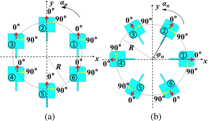
Figure 1: OAM array antennas in different arrangements: (a) CAA (unit translation), (b) RAA (unit rotation).
The chamfered structure is adopted for the array unit to achieve right-handed circular polarization characteristics, and each component of the electric field vector is given in Fig. 1. For CAA, as depicted in Fig. 1 (a), the magnitudes and orientations of the electric field in the X and Y components of each unit are the same, the magnitude in the x direction is 90, and the orientation is the +x direction; the magnitude in the y direction is 0, and the orientation is the +y direction. Therefore, it can be considered that the initial phase difference between adjacent elements of the CAA is 0. If the nth unit of the array is fed with an equal step phase delay (2nl/N) between the elements, the OAM wave with a mode number of l can be successfully excited.
For RAA, as depicted in Fig. 1 (b), the electric field characteristics of the array elements in the back-to-back structure are opposite because the change of the element handedness leads to the change of the electric field size and orientation of each element in the X and Y components, respectively. Therefore, as analyzed in Fig. 1 (b), the theoretical modal values are no longer equal to the modal values produced by the model. The antenna rotates counter-clockwise, so the angle ß between the electric field vector of the nth element and the +x axis is 2(n-1)/N, then the initial phase difference between adjacent elements of the RAA = ß-ß is no longer 0, but 2/N. At this time, the electric field phase delay of the unit can be caused by rotating the antenna. From this, it can be concluded that the phase difference caused by the rotation of the antenna in the RAA is equivalent to the phase difference caused by applying current excitation in the CAA.
B. Simulation
The two structures in Fig. 1 are employed for additional simulation verification in accordance with the theoretical analysis mentioned above. Both antennas are fed by wave port excitation; the radius R of the array is about 0.6. A square plane with a distance of 1000 mm above the array antenna is selected as the observation area, and the component (x or y) in the same direction must be guaranteed for sampling. The only variation between CAA and RAA is the array elements’ various orientations. The simulation results of wavefront phase distribution in different arrangement modes are illustrated in Fig. 2. As seen, both CAA and RAA with six units are capable of producing electromagnetic vortices in the OAM modes of 1, 2, and 3.
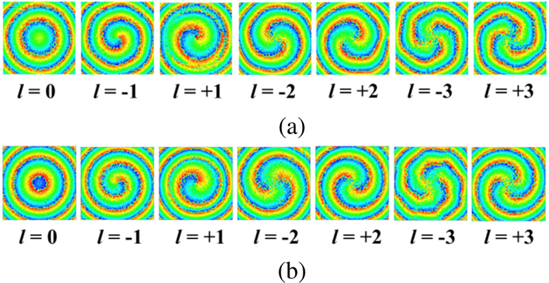
Figure 2: Simulated phase distribution of array antenna under different arrangements: (a) CA, (b) RAA.
The wavefront phase distribution is calculated by collecting the phase value of each point on the wavefront plane, which is a square with sides 800 mm. Furthermore, the wavefront plane should be perpendicular to the radiation direction of the OAM array antenna. As depicted in Fig. 2 (a), the wavefront phase distribution corresponds to the OAM simulation results of CAA, and Fig. 2 (b) corresponds to that of RAA.
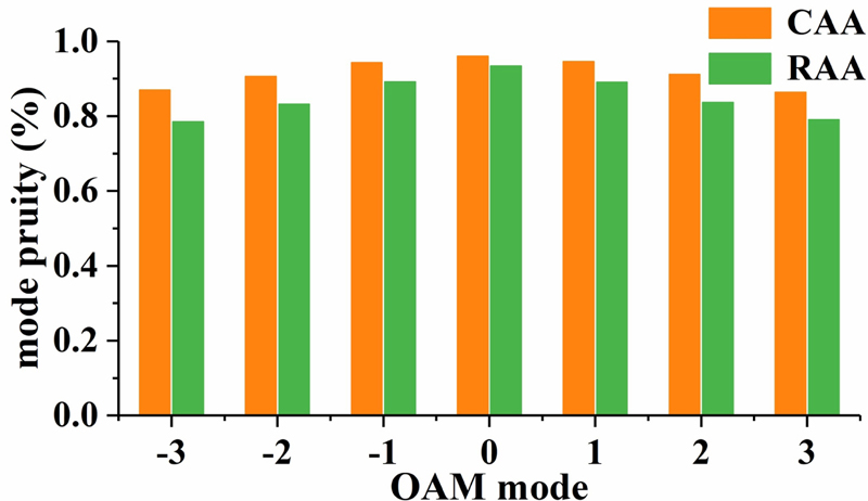
Figure 3: Comparison of the mode purity between CAA and RAA in different OAM modes.
Obviously, the phase distributions of CAA and RAA depicted in Fig. 2 are slightly different, which is due to the array scheme being able to affect the OAM mode purity. For further clarification on the influence of different arrangements, mode purity has been calculated. Figure 3 compares the OAM mode purity of the CAA and RAA in different modes, and the purity of the vortex waves excited by the CAA is higher than that of the same vortex waves generated by the RAA [18]. Therefore, to generate broadband OAM with higher purity, the CAA arrangement is adopted in the following design.
III. BROADBAND OAM ANTENNA
A. Array design
In order to achieve broadband OAM characteristics, the crossed dipole with a single asymmetrical cross-loop is adopted as the array unit [19]. The simulated results of this unit are depicted in Fig. 4. As seen, the crossed dipole antenna performs a -10 dB impedance bandwidth (IBW) of 47.51% (3.455.60 GHz), and the axial ratio bandwidth (ARBW) of 61.51% (3.316.25 GHz), which meet the request of the broadband OAM array antenna.
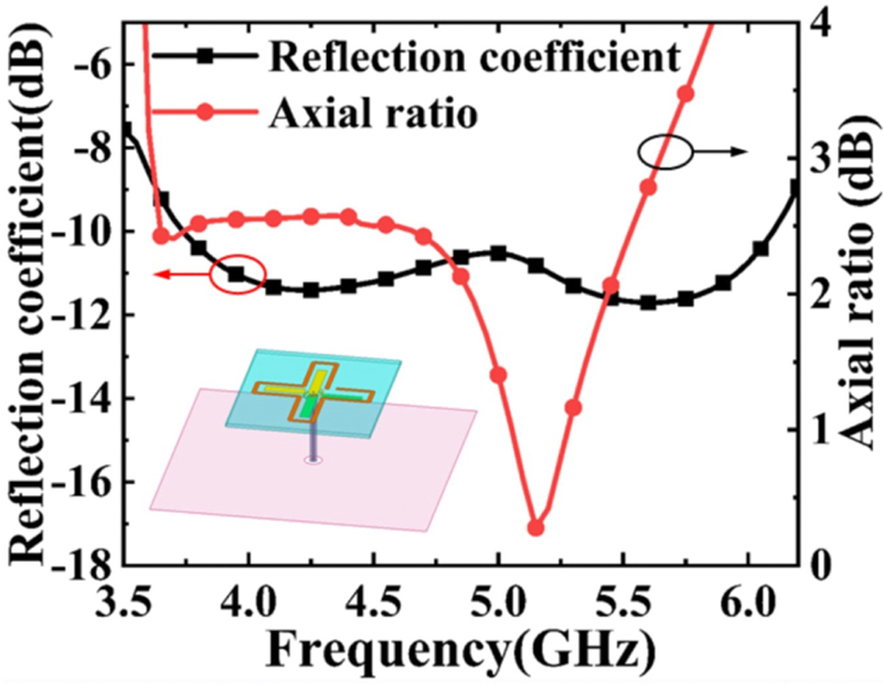
Figure 4: Simulated reflection coefficient and axial ratio of the crossed dipoles.
The configuration and geometric size of the proposed broadband OAM array antenna are illustrated in Fig. 5. This array antenna consists of four crossed dipoles arrayed in CAA and a broadband feeding network with 90 clockwise phase difference. As shown in Fig. 5 (a), these four units are printed on the top layer of substrate 1, and the feeding network is printed on the bottom layer of substrate 2. To save processing cost, the dielectric substrates used in the proposed antenna array are the same, both of which are FR4 materials (= 4.4) with thickness of 0.8 mm.
Taking into account the excitation principle of vortex waves and the integrity of the array antenna structure, a broadband feeding network is designed, as depicted in Fig. 5 (b). The feeding network includes an input port with impedance of 50 and four output ports arranged in the clockwise direction. A 180 phase shifter and two 90 phase shifters are cascaded to form the broadband feeding network. The broadband phase shifter for both 90 and 180 can be equivalent to the three-port device shown in Fig. 5 (b). After passing through the three-port device, one signal is divided into two signals with equal amplitude and phase difference of 90 or 180.
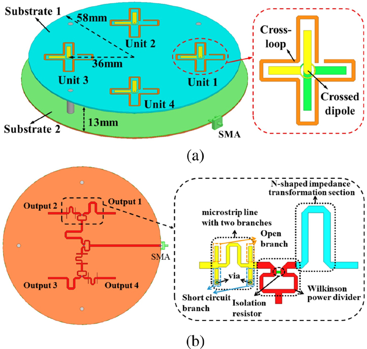
Figure 5: Configuration of the broadband OAM array antenna: (a) 3D view, (b) feeding network.
The proposed planar balun shown in Fig. 5 (b) is composed of a wide-band Wilkinson power divider, a microstrip line with two branches, and an N-shaped impedance transformation section with 90 or 180 phase delay. Among them, the 100 isolation resistor, which plays the role of absorbing echoes and adjusting port isolation, is welded to the Wilkinson power divider. These two branches are an open circuit branch and a short circuit branch connected to a via hole on the ground to realize a short circuit [20]. The amplitude and phase imbalance are stable within a wide operation band.
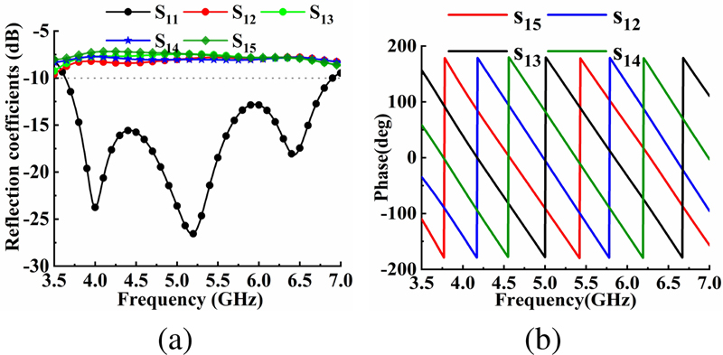
Figure 6: Simulated results of the broadband feeding network: (a) Reflection coefficient, (b) phase shift.
Figure 6 depicts the simulated reflection coefficient and the phase imbalance results of the feeding network. It can be seen from Fig. 6 (a) that the return loss is less than -10 dB in the frequency range of 3.63 GHz6.90 GHz or 62.1%. Additionally, S, S, S, and S are relatively stable, and the maximum amplitude difference between the four output ports does not exceed 1 dB. Figure 6 (b) illustrates that these output phase imbalances of the feeding network are stable within the operation band, and the maximum phase difference of the four signals is less than 3. Therefore, the feeding network has good performance, which provides a good guarantee for the broadband feeding of the CAA.
B. Results and discussions
Table 1: Comparison between reported works and proposed antenna
| Ref. | Type of Unit | Number of Units | Arrangement | Number of Ports | Bandwidth |
| [6] | Aperture-coupled antenna | 24 | CAA+RAA | 1 | 21.3% (13.516.7 GHz) |
| [7] | Triangle patch antenna | 12 | RAA | 2 | 8.7% (8.89.6 GHz) |
| [8] | Circular patch antenna | 4 | RAA | 1 | 21% (2.212.73 GHz) |
| [9] | Bowtie dipole | 4 | RAA | 2 | 25% (2.12.7 GHz) |
| [10] | Closed-loop dipole | 4 | RAA | 1 | 66.9% (2.054.11 GHz) |
| This work | Crossed-dipole | 4 | CAA | 1 | 82.35% (3.58.4 GHz) |
The processed wide-band OAM array antenna and feeding network are assembled, and nylon columns are used to support the upper and lower dielectric substrates. As the signal input end, a 50 claw-shaped SMA connector is soldered to the end of the microstrip line. Photographs of the near-field measuring environment and the antenna’s physical composition are shown in Fig. 7. The antenna was measured in an anechoic chamber. And a broadband receiving antenna on the 3D scanning platform is used to collect the amplitude and phase in the near field. The sampling distance varies from 430 mm (3.5 GHz) to 180 mm (8.4 GHz).
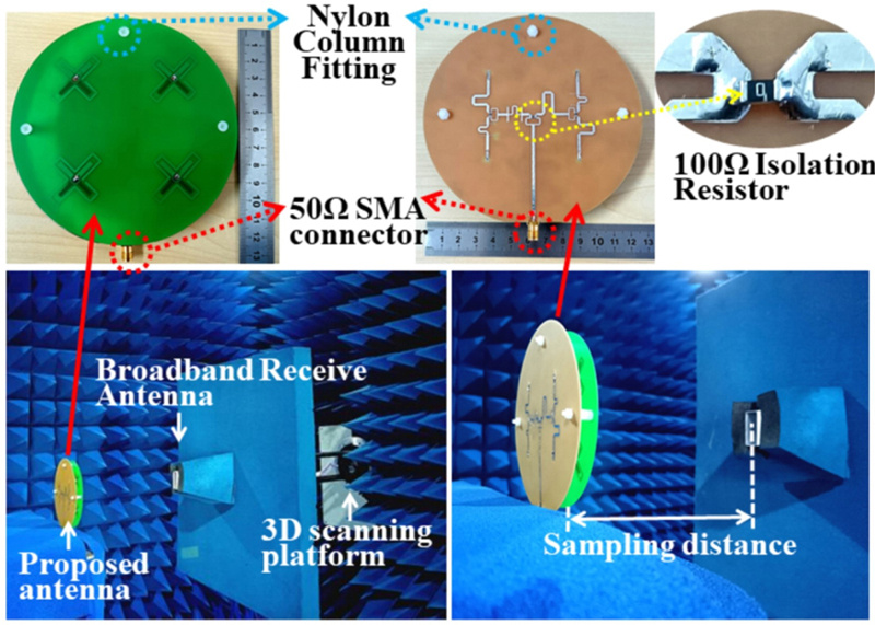
Figure 7: Fabricated prototype of broadband OAM array antenna, and its measurement environment.
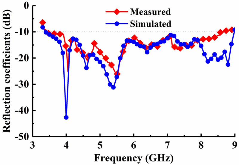
Figure 8: Comparison of simulated results and measured results of reflection coefficient.
The S parameters of the antenna were measured with the vector network analyzer (Ceyear 3635D). Additionally, the results of simulation and measurement are plotted in Fig. 8. As seen, these two curves are quite consistent across most frequency ranges, and the measured results degrade as frequency increases. The test inaccuracy results from the FR4 dielectric substrate’s evident shift in relative dielectric constant with frequency. In addition, machining and welding processes also cause inevitable errors in simulation and measured results. Overall, the consistency between the two is good, and the measured bandwidth essentially agrees with the outcomes of the simulation. It is evident that the bandwidth is greater than that of comparable broadband array antennas and that the -10 dB IBW is 82.35% (3.5-8.4 GHz). A comprehensive comparison with reported works is further conducted, as summarized in Table 1. It shows that the proposed antenna realizes the broadband OAM with fewer units and compact arrangement. It also proves that the analysis of CAA and RAA in section II are effective to the design of the OAM array antenna.
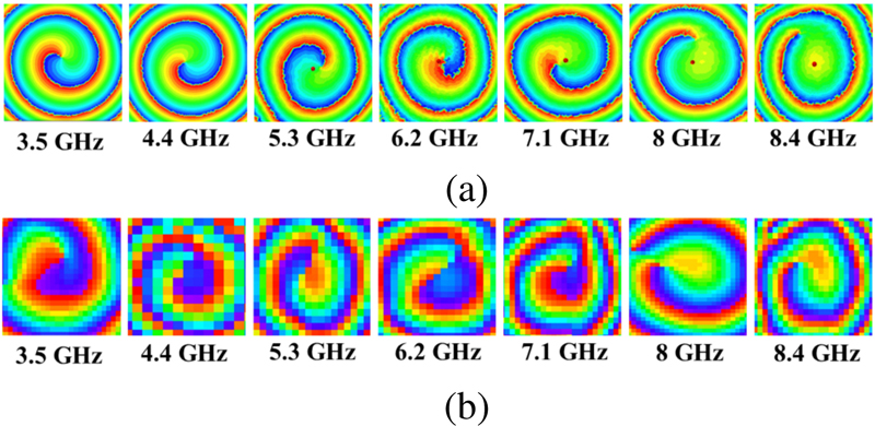
Figure 9: Simulated and measured results of wave-front phase distribution at different frequency points: (a) the simulated results, (b) the measured results.
The distance between the probe and the proposed antenna changes continuously with the change of the test frequency. The fixed scanning range of the wave-front plane is 66, where is the free-space wavelength at the center frequency. And the sampling grid period is 25 mm. In order to prove the broadband OAM characters, the sampling frequency takes 0.9 GHz equally spaced steps, followed by 3.5 GHz, 4.4 GHz, 5.3 GHz, 6.2 GHz, 7.1 GHz, 8 GHz, and 8.4 GHz. Figure 9 compares the simulated and measured wave-front phase distribution of the broadband OAM array antenna in near field at different frequency points. Figure 9 (a) illustrates the OAM phase distribution diagram on the X component. The wave front phase diagram of each frequency point has a clear rotation direction, and it is a curve rotating counter-clockwise, which means the vortex electromagnetic beam with mode +1. Figure 9 (b) depicts the measured results in the near field. It can be seen that the measured results of each frequency point are in good agreement with the simulated ones. The OAM vortex characteristics at different frequency points can be clearly observed from the theoretical simulated and measured results. Therefore, the proposed broadband OAM array antenna successfully excited the OAM beam with mode +1 in the frequency range of 3.5 GHz to 8.4 GHz.
To further demonstrate the effectiveness of the design method, the simulated and measured OAM mode purity of each frequency point is plotted in Fig. 10. The main mode of the proposed antenna is +1, and the purity is over 70% within the whole operation band. It is clear that the wide operation band, high OAM mode purity, compact structure size, and low profile of the proposed antenna exhibit comprehensive advantages.

Figure 10: Simulated and measured OAM mode purity at different frequency points.
IV. CONCLUSION
In this paper, the effects of uniform circular array antennas on vortex electromagnetic waves are analyzed with the units placed in different ways. Compared with the RAA, the CAA arrangement has the advantages of simple principle, easy design, and high purity of excited vortex electromagnetic waves. Furthermore, in order to widen the spectrum resources, a broadband OAM uniform circular array antenna is designed, fabricated, and measured. The simulation and experimental results show that it exhibits obvious and stable vortex wave characteristics in the wide frequency band of 3.58.4 GHz. The proposed broadband OAM array antenna has broad application prospects in underwater short-range communication, radar imaging, and so on.
ACKNOWLEDGMENTS
This work is supported in part by Key Research and Development Program of Shaanxi (Program No. 2021GY-049), Scientific Research Program funded by Shaanxi Provincial Education Department (Program No. 22JC058), and Xi’an Science and Technology Plan Project under Grant 21XJZZ0071.
REFERENCES
[1] N. Jindal, “MIMO broadcast channels with finite-rate feedback,” IEEE Trans. Inf. Theory, vol. 52, no. 11, pp. 5045-5060, 2006.
[2] M. Ergen, S. Coleri, and P. Varaiya, “QoS aware adaptive resource allocation techniques for fair scheduling in OFDMA based broadband wireless access systems,” IEEE Trans. Broadcast., vol. 49, no. 4, pp. 362-370, 2003.
[3] H.-T. Chen, R. Pan, W.-Z. Sun, and S.-Y. Si, “Microstrip reflectarray for generation of electromagnetic waves with beam vorticity,” Applied Computational Electromagnetics Society (ACES) Journal, vol. 33, no. 5, pp. 488-493, 2018.
[4] X.-N. Hui, S.-L. Zheng, Y. P. Hu, X. Chen, X.-F. Jin, H. Chi, and X.-M. Zhang, “Ultralow reflectivity spiral phase plate for generation of millimeter-wave OAM beam,” IEEE Antennas Wirel. Propag. Lett., vol. 14, no.0, pp. 966-969, 2015.
[5] W.-T. Zhang, S.-L. Zheng, X.-N. Hui, Y.-L. Chen, X.-F. Jin, H. Chi, and X.-M. Zhang, “Four-OAM-Mode antenna with traveling-wave ring-slot structure,” IEEE Antennas Wirel. Propag. Lett., vol. 16, no. 0, pp. 194-197, 2017.
[6] H. Xu, H. Liu, X. Ling, Y. Sun, and F. Yuan, “Broadband vortex beam generation using multimode pancharatnam–berry metasurface,” IEEE Trans. Antennas Propag., vol. 65, no. 12, pp. 7378-7382, 2017.
[7] Y.-L. Zhou, X.-N. Li, K.-Y. Yao, Y.-M. Huang, and H.-Y. Jin, “A topological charge continuously tunable orbital angular momentum (OAM) electromagnetic wave generation method based on fixed-length delay line mixing circuit,” Applied Computational Electromagnetics Society (ACES) Journal, vol. 37, no. 10, pp. 1071-1076, 2023.
[8] Y. Zhang and J. Li, “An orbital angular momentum-based array for in-band full-duplex communications,” IEEE Antennas Wirel. Propag. Lett., vol. 18, no. 3, pp. 417-421, 2019.
[9] T.-Z. Zhang, J. Hu, Q.-Y. Zhang, D. Zhu,Y.-B. Ma, B.-T. Lin, and W. Wu, “A compact multimode OAM antenna using sequentially rotated configuration,” IEEE Antennas Wirel. Propag. Lett., vol. 21, no. 1, pp. 134-138, 2022.
[10] Q. Liu, Z.-N. Chen, Y.-N. Liu, F.-H. Li, Y. Chen, and Z.-G. Mo, “Circular polarization and mode reconfigurable wideband orbital angular momentum patch array antenna,” IEEE Trans. Antennas Propag., vol. 66, no. 4, pp. 1796-1804, 2018.
[11] B. Liu, Y. Cui, and R. Li, “A broadband dual-polarized dual-OAM-mode antenna array for OAM communication,” IEEE Antennas Wirel. Propag. Lett., vol. 16, no. 0, pp. 744-747, 2017.
[12] Z. Yang, J. Zhou, L. Kang, B. Liu, G. Yang, and X. Shi, “A closed-loop cross-dipole antenna array for wideband OAM communication,” IEEE Antennas Wirel. Propag. Lett., vol. 19, no. 12, pp. 2492-2496, 2020.
[13] Z. Li, S. Li, B. Han, G. Huang, L. Cong, and X. Cao, “A broadband magnetic-electric dipole antenna array for OAM generation,” 2021 International Conference on Microwave and Millimeter Wave Technology (ICMMT), pp. 1-3, 2021.
[14] T. Yang, D. Yang, B. Wang and J. Hu, “Experimentally validated, wideband, compact, OAM antennas based on circular Vivaldi antenna array,” Progress In Electromagnetics Research C, vol. 80, pp. 211-219, 2018.
[15] K. Liu, H.-Y. Liu, Y.-L. Qin, Y.-Q. Cheng, S.-N. Wang, X. Li, and H.-Q. Wang, “Generation of OAM beams using phased array in the microwave band,” IEEE Trans. Antennas Propag., vol. 64, no. 9, pp. 3850-3857, 2016.
[16] L. Li and X.-X. Zhou, “Mechanically reconfigurable single-arm spiral antenna array for generation of broadband circularly polarized orbital angular momentum vortex waves,” Scientific Reports, vol. 8, no. 1, pp. 1-9, 2018.
[17] Q. Feng, Y.-F. Lin, Y.-S. Zheng, and L. Li, “Vortex beam optimization design of concentric uniform circular array antenna with improved array factor,” Applied Computational Electromagnetics Society (ACES) Journal, vol. 36, no. 7, pp. 830-837, 2021.
[18] J. Ma, X. Song, Y. Yao, Z. Zheng, X. Gao, and S. Huang, “Research on the purity of orbital angular momentum beam generated by imperfect uniform circular array,” IEEE Antennas Wirel. Propag. Lett., vol. 20, no. 6, pp. 968-972, 2021.
[19] G. Feng, L. Chen, X. Xue, and X. Shi, “Broadband circularly polarized crossed-dipole antenna with a single asymmetrical cross-loop,” IEEE Antennas Wirel. Propag. Lett., vol. 16, no. 0, pp. 3184-3187, 2017.
[20] Z.-Y. Zhang, Y.-X. Guo, L.-C. Ong, and M. Y. W. Chia, “A new wide-band planar balun on a single-layer PCB,” IEEE Microw. Wireless Compon. Lett., vol. 15, no. 6, pp. 416-418, 2005.
BIOGRAPHIES

Yunqi Zhang was born in BaoTou, Inner Mongolia, China. He received the Master’s degree and the Ph.D. degree in micro-electronics from Xidian University in 2012 and 2015, respectively. He is currently working in the Xi’an University of Posts & Telecommunications. His research interests include CP antennas, OAM, omnidirectional antennas, and phase array antennas.

Shiliu Zhao is with the School of Electronic Engineering, Xi’an University of Posts & Telecommunications, Xi’an 710121, China. Her main research interests are array antennas and vortex electromagnetic waves.

Xuping Li was born in Xi’an, Shanxi, China in 1981. He received the Ph.D. degree in electromagnetic fields and microwave technology from Xidian University, Xi’an, China, in 2015. His research interests are antenna theory and engineering.

Leying Wang is with the School of Electronic Engineering, Xi’an University of Posts & Telecommunications, Xi’an 710121, China. Her current research interests include underwater wireless optical communication and signal processing.
ACES JOURNAL, Vol. 38, No. 7, 489–495
doi: 10.13052/2023.ACES.J.380704
© 2023 River Publishers