A Compact Circularly Polarized Crossed Dipole Antenna with Wide Bandwidth using Split Ring Resonator and Parasitic Patches
Hailong Yang, Zhiqiang Guo, Xuping Li, Yunqi Zhang, Xueyan Song, and Shanzhe Wang
School of Electronic Engineering
Xi’an University of Posts and Telecommunications, Xi’an, 710121, China
yanghl68@163.com, 1148958181@qq.com, lixuping@163.com, johnny_5@126.com, xysong6597@126.com, 14120032@bjtu.edu.cn
Submitted On: November 30, 2022; Accepted On: April 16, 2022
ABSTRACT
A new compact broadband circularly polarized (CP) crossed dipole antenna using split ring resonator (SRR) and parasitic patches are presented. The proposed antenna is mainly composed of two orthogonal strip dipoles, two 90 phase delay lines, four SRRs, and four parasitic patches. The combination of the orthogonal strip dipoles and the delay lines forms a crossed dipole as the main CP radiator. The well-designed SRR can extend the current path and improve the current distribution of high-frequency without increasing the size of the antenna, thereby reducing the size of the antenna and increasing the axial ratio (AR) bandwidth of the high-frequency. The introduction of parasitic patches can improve the current distribution between the upper and lower cut-off frequency points of the bandwidth, and make up for the defects of the insufficient bandwidth of the crossed dipole and the SRR, thereby realizing broadband CP radiation. To verify the antenna, a physical prototype is fabricated. The measured results show that the impedance bandwidth (IBW) of 69.1% (1.38-2.84 GHz), and a wide AR bandwidth of 57.7% (1.43-2.59 GHz). In addition, the designed antenna achieves a stable gain in the working band and a certain band-edge selectivity. Such a single-fed, simple structure and the wideband CP antenna is an excellent candidate for communication systems such as ISM (2.4 GHz), WiBro (2.3-2.39 GHz)and Inmarsat.
Index Terms: Circularly Polarized (CP) antenna, crossed dipole, parasitic patches, Split Ring Resonator (SRR).
I. INTRODUCTION
Compared to linearly polarized antennas, circularly polarized (CP) antennas have received widespread attention due to their advantages of eliminating polarization mismatches and suppressing multipath interference. At the same time, there are no strict requirements for the direction of transmitting and receiving antennas, which can improve the flexibility between transmitting and receiving antennas. In recent years, with the development of miniaturization and integration of wireless communication systems, miniaturization and broadband CP antennas have attracted more and more attention.
The traditional CP crossed dipole antennas use a phase-delay ring to provide orthogonal phase and generate CP radiation [1]. The circumference of the ring is one-quarter of the waveguide wavelength corresponding to the center frequency, and its size is small and easy to design, with an axial ratio (AR) bandwidth of up to 15.6%. Although this bandwidth has a significant advantage over traditional circularly polarized patch antennas, it has only a single resonant mode, which is not competitive enough in modern wireless communication systems. There have been many papers [2]-[15] that have reported on further expanding the CP bandwidth of the crossed dipole antenna. In [2], Feng, et al. proposed a crossed dipole antenna loading an asymmetric cross-loop, and achieving a 53.4% CP bandwidth in the form of a multi-mode resonance. Similarly, by introducing structures such as parasitic magneto-electric dipoles [3], two parasitic patches [4], dual cavity [5], and parasitic modified patches [6], the bandwidths can reach 28.6%, 66%, 66.7%, and 72.7%, respectively. However, the introduction of the above-mentioned parasitic structures leads to an increase in the size of the antenna. In [7]-[10], by improving the early linear crossed dipoles, the rectangular crossed dipole [7], double bowtie crossed dipole [8], asymmetric bowtie crossed dipole [9], and L-shaped crossed dipole [10] are used. The matching of broadband is improved, and the final CP bandwidth reaches 27%, 26.3%, 51%, and 62.3%, respectively. In [11], a wideband and directional crossed dipole CP antenna is studied. By adding the parasitic patches and defecting the ground plane, the CP bandwidth is enhanced. In [12], the stepped dipole and L-shaped folded ground plate is designed to enhance the CP operation bandwidth of a crossed dipole antenna. Although, in [11] and [12], their CP bandwidths can reach 68.6% and 74.7%, respectively, their sizes are 0.97 0.97 and 1.03 1.03 , which is still relatively large. In [13] and [14], the size of the deformed crossed dipole antenna with four parasitic plates and the crossed dipole antenna using coupling stubs can reach 0.4 0.4 and 0.32 0.32 , respectively. However, the CP bandwidths of these two antennas are only 52.6% and 45%, which is narrower than the antennas [11] and [12]. In [15], a wideband CP crossed dipole antenna with improved bandwidth and gain performance is presented. By designing parasitic elements, a cavity-backed reflector, and a circular ring reflector, good CP bandwidth and high gain are obtained. The size of the antenna in [15] is 0.6 0.6 , and the CP bandwidth is 85.5%. Nevertheless, the structure of the antenna is complex and the assembly is difficult, which increases the difficulty of debugging the antenna. Therefore, it is of interest to design crossed dipole antennas with a simple structure, small size, and wide bandwidth.
In this paper, a crossed dipole antenna with a simple structure, small size, and wide CP bandwidth is proposed, and it has been validated in [16]. In this design, the well-designed SRR makes good use of its resonant properties to produce multiple resonant modes by coupling with the crossed dipole. The introduction of parasitic patches can improve the current distribution between the upper and lower cut-off frequency of the bandwidth, and make up for the defects of the insufficient bandwidth of the crossed dipole and the SRR, thereby realizing wide CP bandwidth. The size of the antenna is 0.66 0.66 . The measured results reveal that the IBW of the antenna is 69.1% (1.38-2.84 GHz), the CP bandwidth is 57.7% (1.43-2.59 GHz) and the gain is stable within the working bandwidth. In addition, since the crossed dipole and the SRR adopt the narrow-band resonance mode, the antenna shows good band-edge selectivity in the upper and lower sidebands. In general, the antenna has good advantages in size, structure, and performance index, and can be used as an alternative product in the field of satellite communication and RFID.
II. ANTENNA DESIGN AND ANALYSIS
A. Antenna configuration
Figure 1 shows the configuration of the proposed compact broadband CP crossed dipole antenna, which is mainly designed on an FR4 substrate with relative dielectric constant r = 4.4 and a thickness of 0.8 mm. The proposed antenna consists of two orthogonal strip dipoles, two symmetrical 90 phase delay lines, four SRRs, four parasitic patches, and a metal reflector plate. The orthogonal dipoles printed on the upper and lower sides of the substrate are connected by delay lines to realize CP radiation. The interaction of the four SRRs with the crossed dipole produces two resonant modes at high and low frequencies, increasing the IBW as well as the axial ratio (AR) bandwidth. To obtain a better AR bandwidth, four rectangular patches with chamfered corners were introduced. In addition, the metal reflective plate of size L L is added 1/4 below the dielectric plate, which can better enhance the unidirectional radiation performance of the antenna. The dielectric plate and the reflector are supported by four nylon columns to maintain the stability of the antenna. Finally, the optimal results are obtained by optimizing the parameter characteristics through HFSS. In the simulation optimization, the excitation type of the antenna adopts a lumped port setting, and the size of the radiation box is selected to be no less than a quarter of the working wavelength of the low frequency from the antenna edge. The optimal parameters of the antenna are shown in Table 1.
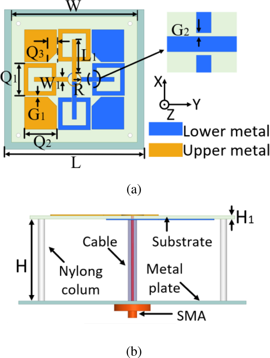
Figure 1: Configuration of the proposed antenna. (a) Top view. (b) Side view.
Table 1: Antenna parameters (units: mm)
| L | W | L | W | R | G |
| 100 | 90 | 23 | 3.1 | 4.6 | 1.1 |
| G | Q | Q | Q | H | H |
| 0.2 | 23 | 17 | 6.6 | 36 | 0.8 |
B. Antenna mechanism
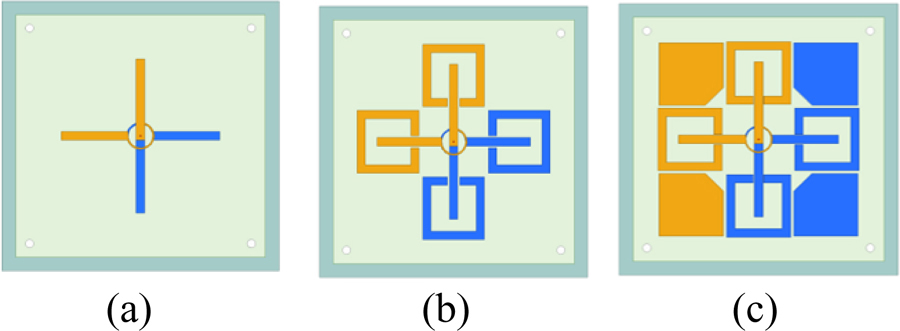
Figure 2: Research process of the proposed antenna. (a) Antenna-I. (b) Antenna-II. (c) Antenna-III.
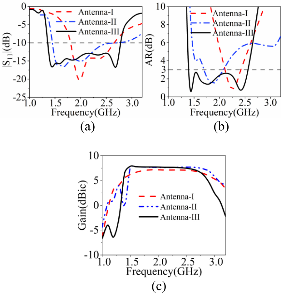
Figure 3: Simulated results of the Antenna-I, Antenna-II, and Antenna-III. (a) |S|. (b) AR. (c) Gain.
To better explain the working mechanism of the antenna, Fig. 2 shows the evolution process of the antenna, and Fig. 3 shows the relationship between the corresponding simulated reflection coefficient and the AR as a function of frequency. As shown in Fig. 2 (a), Antenna-I is an early crossed dipole antenna consisting of orthogonal dipoles connected with delay lines. The simulation results in Fig. 3 show that Antenna-I has only one resonant mode corresponding to the dipole length, the matching bandwidth and the AR bandwidth are relatively narrow, and the AR bandwidth is only 15.6%. As shown in Fig. 2 (b), the modified Antenna-II is composed of four SRRs interacting with the crossed dipole. On the one hand, this ingenious design can extend the low-frequency current path, reduce the electrical size of the antenna, and realize the compact of the antenna. On the other hand, the SRR resonant characteristic can increase the resonant frequency point and generate two resonant modes of high frequency and low frequency, thus realizing the expansion of the working bandwidth. As can be seen from Fig. 3, compared with Antenna-I, the matching bandwidth of the modified Antenna-II is significantly enhanced, and a new AR bandwidth is introduced. However, between the high frequency and low frequency resonant frequency points, their AR is stillnot ideal.
To further obtain the wide AR bandwidth, four rectangular patches with chamfered corners are introduced, and the introduction of parasitic chamfered patches has a positive effect on the SRR current distribution, which can improve the resonant mode between high and low frequencies. The design of the chamfered corner is to further improve the amplitude ratio of the two orthogonal electric fields in the working frequency band and help the antenna to achieve a good AR bandwidth. In addition, it can be seen from Fig. 3 (c) that the introduction of the SRR causes the antenna to generate a radiation null at low frequency. This is because of the resonance characteristic of the SRR. To verify the radiation null, the equivalent LC resonant circuit of the SRR is shown in Fig. 4 [17], [18]. The L value depends on the length (Q and Q) of the SRR, and the C value is determined by G. To illustrate the radiation null, the parameters Q and Q of Antenna-II are analyzed in Fig. 5. It is observed that the low-frequency radiation null point can be adjusted by the size of the SRR. Furthermore, the current distribution on the parasitic patch affects the SRR, which has excellent sideband selection characteristics at low frequencies, and a 3 dB drop at high frequencies. Thereby a better band-edge selectivity of the antennais realized.

Figure 4: Equivalent LC circuit of the SRR.
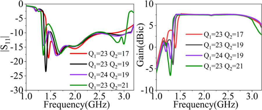
Figure 5: The simulated |S| and gain with different values of Q and Q.
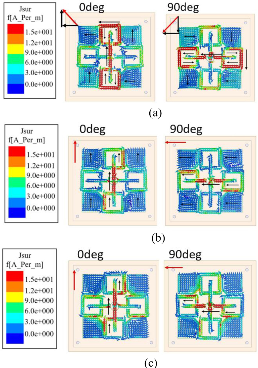
Figure 6: Simulated current distributions of the antenna. (a) 1.45 GHz, (b) 1.8 GHz, and (c) 2.4 GHz.
To verify the CP radiation characteristics of the designed antenna, Fig. 6 shows the current distribution diagrams of the antenna at 1.45 GHz, 1.8 GHz, and 2.4 GHz frequency points. It can be seen from Fig. 6 (a) that the vertical current components of the 0 phase SRR cancel each other at low frequency of 1.45 GHz, so the dominant current is synthesized by the horizontal current of the SRR and the vertical current of the dipoles. The dominant current in the 90 phase at low frequency of 1.45 GHz is composed of the vertical current of the SRR and the horizontal current of the dipole. Figure 6 (b) shows that the current direction at 1.8 GHz is dominated by dipoles. The SRR and the parasitic patch affect the vertical and horizontal current distribution, which is the main factor to realize the CP mode. As shown in Fig. 6 (c), the current at 2.4 GHz is mainly distributed on the dipole. Therefore, the CP radiation is achieved mainly through dipoles and phase delay lines at high frequencies. As can be seen from Fig. 6, according to the rotation direction of the current, it can be concluded that the current flows in the counter-clockwise direction along the +z direction in the working frequency band, so the antenna generates right-handed circularly polarized (RHCP) waves.
III. SIMULATED AND MEASURED RESULTS
To verify the accuracy of the proposed antenna, a prototype was fabricated, as shown in Fig. 7 (a). The reflection coefficient of the proposed antenna is measured by Agilent-89441A VNA, and the gains, ARs and radiation patterns are measured in a Far-field microwave anechoic chamber. As can be seen in Fig. 7 (a), the measured and simulated IBW of the proposed antenna are 69.6% (1.35-2.79 GHz) and 69.1% (1.38-2.84 GHz), respectively. The simulated results are in good agreement with the measured results. Figure 7 (b) shows the measured and simulated results of AR and gain. As illustrated in Fig. 7 (b), the measured and simulated 3 dB AR bandwidths are 57.7% (1.43-2.59 GHz) and 58.5% (1.4-2.56 GHz) respectively. Compared with the simulated results, the working frequency band is slightly shifted to the right in the measured results, which may be caused by the dielectric constant error of the substrate and the processing error. Figure 7 (b) illustrates the measured and simulated gain results are in good agreement, and the in-band fluctuation is less than 1.5 dB, which shows good in-band flatness. In addition, the reflection coefficient and gain of the antenna all show good sideband selection characteristics, which gives the antenna a certain filtering function. Figure 8 shows the measured and simulated radiation patterns for two principal planes (xoz and yoz) at 1.45 GHz, 1.8 GHz, and 2.4 GHz, respectively. The simulated results agreed well with the measured results. It can be observed that the RHCP waves are at least 15 dB larger than the left-handed Circularly Polarized (LHCP) waves, which means that the antenna radiates RHCP waves.
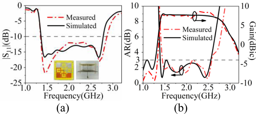
Figure 7: Measured and simulated results of the proposed antenna. (a) |S| (a prototype is shown as an insert). (b) AR and gain.
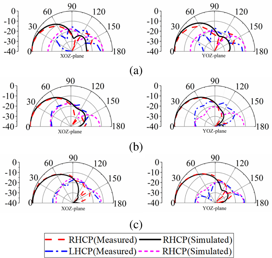
Figure 8: Measured and simulated radiation patterns in xoz and yoz planes for the antenna at three frequencies. (a) 1.45 GHz. (b) 1.8 GHz. (c) 2.4 GHz.
Table 2: Comparison between the proposed and other works
| Ref | Overall Size() | IBW | ARBW | Band-edge Selectivity | Average Gain (dBic) |
| [2] | 1.11.10.28 | 67.5% | 53.4% | NO | 8.0 |
| [4] | 1.041.040.26 | 77.6% | 66% | NO | 7.2 |
| [5] | 0.790.790.27 | 95.0% | 58.6% | NO | 8.2 |
| [9] | 0.880.880.23 | 78.3% | 51% | NO | 9.6 |
| [11] | 0.970.970.32 | 82% | 68.2% | NO | 8.0 |
| [13] | 0.40.40.13 | 68.9% | 52.4% | NO | 3.0 |
| Pro | 0.660.660.25 | 69.1% | 57.7% | YES | 7.7 |
: operating wavelength in free space at the center frequency.
To highlight the novelty of the proposed antenna, Table 2 lists a comparison of the performance between this paper and other references [4], [6], [7], [11], [13] and [15]. Compared with the references in [6] and [11], the proposed antenna is smaller in size. In addition, the proposed antenna has a wider CP bandwidth than the antennas in [11] and [15], and has a higher gain than the antenna in [15]. Although the CP bandwidth in [7] is the same as the proposed antenna, the size of the antenna in [7] is larger than the proposed antenna. Moreover, the proposed antenna has good band-edge selectivity and stable radiation pattern in the working frequency band.
IV. CONCLUSION
In this study, a compact wideband CP antenna using SRR and parasitic patches has been presented. By adding the well-designed SRRs close to the crossed dipoles, the current path and the current distribution can be well modified, also the size of the antenna and the AR bandwidth of the high-frequency can be improved. In addition, the introduction of parasitic patches can improve the current distribution between the upper and lower cut-off frequency points of the bandwidth, and make up for the defects of the insufficient bandwidth of the crossed dipole and the SRR, thereby realizing broadband CP radiation. The measured results show an IBW of 69.1% (1.38-2.84 GHz), and a wide AR bandwidth of 57.7% (1.43-2.59 GHz). Moreover, the designed antenna achieves a stable gain in the working band and good band-edge selectivity, which can be used as a candidate for ISM band, WiBro and Inmarsat communication systems.
ACKNOWLEDGMENT
This work was supported by the Natural Science Basic Research Program of Shannxi Province, China (Grant No. 2021JQ-710), (Grant No. 2021GY-049), (Grant No. 2022JQ-699), in part by Xi’an Science and Technology Plan Project under Grant 2021JH-06-0038, 2020KJRC0102.
REFERENCES
[1] J. W. Baik, K. J. Lee, W. S. Yoon, T. H. Lee, and Y. S. Kim, “Circularly polarised printed crossed dipole antennas with broadband axial ratio,” Electron. Lett., vol. 44, no. 13, pp. 785-786,June 2008.
[2] G. Feng, L. Chen, X. Xue, and X. Shi, “Broadband circularly polarized crossed-dipole antenna with a single asymmetrical cross-loop,” IEEE Antennas Wireless Propag. Lett., vol. 16, pp. 3184-3187, Oct. 2017.
[3] S. X. Ta and I. Park, “Crossed dipole loaded with magneto-electric dipole for wideband and wide-beam circularly polarized radiation,” IEEE Antennas Wireless Propag. Lett., vol. 14, pp. 358-361, Oct. 2015.
[4] L. Wang, W.-X. Fang, Y.-F. En, Y. Huang, W.-H. Shao, and B. Yao, “Wideband circularly polarized cross-dipole antenna with parasitic elements,” IEEE Access., vol. 7, pp. 35097-35102, Mar. 2019.
[5] T. K. Nguyen, H. H. Tran, and N. Nguyen-Trong, “A wideband dual-cavity-backed circularly polarized crossed dipole antenna,” IEEE Antennas Wireless Propag. Lett., vol. 16, pp. 3135-3138, Oct. 2017.
[6] Z. Zhao, Y. Li, M. Xue, L. Wang, Z. Tang, and Y. Yin, “Design of wideband circularly polarized crossed-dipole antenna using parasitic modified patches,” IEEE Access., vol. 7, pp. 75227-75234, June 2019.
[7] Y. He, W. He, and H. Wong, “A wideband circularly polarized cross-dipole antenna,” IEEE Antennas Wireless Propag. Lett., vol. 13, pp. 67-70, Jan. 2014.
[8] M. Elsaid, K. R. Mahmoud, M. Hussein, M. F. Hameed, A. Yahia, and S. S. Obayya, “Ultra-wideband circularly polarized crossed-dual-arm bowtie dipole antenna backed by an artificial magnetic conductor,” Microw. Opt. Technol. Lett., vol. 61, no. 12, pp. 2801-2810, Aug. 2019.
[9] H. H. Tran and I. Park, “Wideband circularly polarized cavity-backed asymmetric crossed bowtie dipole antenna,” IEEE Antennas Wireless Propag. Lett., vol. 15, pp. 358-361, June 2016.
[10] X. Liang, J. Ren, L. Zhang, C. He, J. Geng, W. Zhu, and R. Jin, “Wideband circularly polarized antenna with dual-mode operation,” IEEE Antennas Wireless Propag. Lett., vol. 18, no. 4, pp. 767-770, Apr. 2019.
[11] Z. Guo, Z. Zhao, Y. Yang, and X. Ding, “A directional circularly polarized crossed dipole antenna with bandwidth enhancement,” Microw. Opt. Technol. Lett., vol. 60, no. 9, pp. 2161-2167, Sep. 2018.
[12] L. Wang, K. Chen, Q. Huang, L. Wang, K. Chen, Q. Huang, W. Shao, W. Fang, G. Lu, and Y. Huang, “Wideband circularly polarized cross-dipole antenna with folded ground plane,” IET Microw. Antennas Propag., vol. 15, no. 5, pp. 451-456, Apr. 2021.
[13] H. Zhang, Y. Guo, and G. Wang, “A design of wideband circularly polarized antenna with stable phase center over the whole GNSS bands,” IEEE Antennas Wireless Propag. Lett., vol. 18, no. 12, pp. 2746-2750, Dec. 2019.
[14] L. Wen, S. Gao, B. Sanz-Izquierdo, C. Wang, W. Hu, X. Ren, and J. Wu, “Compact and wideband crossed dipole antenna using coupling stub for circular polarization,” IEEE Trans. Antennas Propag., vol. 70, no. 1, pp. 27-34, Jan. 2022.
[15] Y. Feng, J. Li, B. Cao, J. Liu, G. Yang, and D. Wei, “Cavity-backed broadband circularly polarized cross-dipole antenna,” IEEE Antennas Wireless Propag. Lett., vol. 18, no. 12, pp. 2681-2685, Dec. 2019.
[16] Z. Guo, X. Li, H. Yang, J. Zhang, and C. Zheng, “Compact circularly polarized crossed dipole antenna with wide bandwidth and wide axial ratio,” 13th International Symposium on Antennas, Propagation and EM Theory (ISAPE), Zhuhai, China, vol. 1, pp. 1-3, Dec. 2021.
[17] P. Jha, A. Kumar, A. De, and R. K. Jain, “Super ultra-wideband planar antenna with parasitic notch and frequency selective surface for gain enhancement,” Applied Computational Electromagnetics Society (ACES) Journal, vol. 37, no. 7, pp. 757-764, Dec. 2022.
[18] P. Jha, A. Kumar, A. De, and R. K. Jain, “CPW-fed metamaterial inspired compact multiband antenna for LTE/5G/WLAN communication,” Frequenz, vol. 76, no. 7-8, pp. 401-407, Aug. 2022.
BIOGRAPHIES

Hailong Yang received his B.S. in Communication Engineering from Heze University, Heze, China, in 2012. He received his M.S. and Ph.D degrees in Communication Engineering from Xi’an University of Technology, Xi’an, China, in 2015 and 2019 respectively. He joined the faculty of the Electronic Engineering Department, Xi’an University of Posts and Telecommunications, in 2019. His research interests include wave propagation and antenna design.

Zhiqiang Guo was born in Henan Province, China, 1997. He is currently pursuing a Master of Engineering degree at the School of Electronic Engineering, Xi’an University of Posts and Telecommunications. His current research interests include circularly polarized antennas, filtering antennas and array antennas.

Xuping Li was born in Xi’an, Shanxi, China in 1981. He received his Ph.D. degree in Electromagnetic Fields and Microwave Technology from Xidian University, Xi’an, China, in 2015. His research interests are antenna theory and engineering.

Yunqi Zhang was born in BaoTou, Inner Mongolia, China. He received his Ph.D. degree from Xidian University, Xi’an, China in 2015. He is currently working at the Xi’an University of Posts and Telecommunications. In 2017 he joined the school of Physics and Optoelectronic Engineering, Xidian University, as a post doctoral researcher. His research interests include GPS antennas, CP antennas, omnidirectional antennas and antenna array designs.

Xueyan Song was born in Henan Province, China, 1989. She received her B.E. degree in Electronic and Information Engineering from Xidian University, Xi’an, China, in 2012. She received her Ph.D. degree in Electromagnetic Fields and Microwave Technology from Xidian University, Xi’an, China, in 2018.
She joined the School of Electronic Engineering, Xi’an University of Posts and Telecommunications in 2018. Her research interests include artificial magnetic conductors, low RCS antennas, low-profile antennas, frequency selective surfaces and reflector antennas.

Shanzhe Wang received his M.S. degree in Electronic Science and Technology from Beijing Jiaotong University, Beijing, China, in 2017. He received his Ph.D. degree in Electronic Science and Technology from Beijing Jiaotong University, Beijing, China, in 2022.
He joined the School of Electronic Engineering, Xi’an University of Posts and Telecommunications in 2022. His research interests include fixed-frequency beam-scanning leaky-wave antennas.
ACES JOURNAL, Vol. 38, No. 4, 224–230
doi: 10.13052/2023.ACES.J.380401
© 2023 River Publishers