A Three-dimensional Compact Propeller-shaped Circularly Polarized Ceiling Antenna
Jia-Xiang Chen, Hai-Tao Xing, Jian-Mei Huang, Meng-Nan Wang, and Zhong-Hua Ma
School of Marine Information Engineering
Jimei University, Xiamen, Fujian, 361021, China
chenjx7335@jmu.edu.cn; xht2005@jmu.edu.cn; 202021112035@jmu.edu.cn;
202211810012@jmu.edu.cn; mzhxm@jmu.edu.cn
Corresponding author: xht2005@jmu.edu.cn
Submitted On: January 3, 2023; Accepted On: May 1, 2023
ABSTRACT
A three-dimensional compact propeller-shaped circularly polarized ceiling-mounted antenna loaded by inverted L-shaped slot is proposed in this paper. This three-dimensional structure has a small size, single feed and half-plane radiation mode. The antenna is composed of four alternately welded radiating elements and a disc reflector. Each radiating element is formed by etching a rectangular microstrip radiating patch and a trapezoidal microstrip radiating patch on the surface of the substrate. The four radiating elements are welded vertically on the disc reflector. The back of the disc reflector has the ground plane. The antenna is fed coaxially through the via in the center of the disc reflector. The result demonstrates that the 10-dB impedance fractional bandwidth achieves 66.3% (4.4-8.94 GHz). The 3-dB axial ratio fractional bandwidth is 2.2% (6.44-6.58 GHz). The radiation characteristic is close to half-space radiation on the xoz plane and the yoz plane. The peak gain of the antenna is 3.22 dBi. The simulation and measurement results are in good agreement. With its compact structure, effective coverage, miniaturization, etc., the antenna is very suitable for applications such as biomedical monitoring equipment and short-rangeradio communications.
Index Terms: axial ratio (AR), circular polarization (CP), coaxial feed, inverted L-shaped slot, three-dimensional.
I. INTRODUCTION
With the rapid development of modern wireless communications and the increasing number of communication systems, circularly polarized (CP) antennas have attracted more and more attention due to their excellent performance and have been widely used in wireless communication systems [1].The attractive benefit of CP antennas is that it can send and receive signals in all planes having strong absorption and reflection of radio signals [2]. Attributing to the requirement of great capacity and higher transmission rate of 5G in the future, it is difficult to find spectrum resources with large bandwidths of up to 100 MHz or even hundreds of megahertz for spectrum below 6 GHz. Spectrum above 6 GHz is an important source for 5G to find new frequency bands. The use of spectrum above 6 GHz for 5G has become a global consensus [3]. Because the antenna proposed in this article has good directivity and compact structure, it has potential application for indoor positioning, unmanned aerial vehicles (UAVs), automobiles and other point-to-point communication, or in subway stations and conference halls etc.
Circularly polarization characteristics of antenna can be achieved by many methods, such as cutting corners [4], rotated stacked [5] and stub line loading [6], selecting a suitable feed point location and multiple feeding ports [7]. The CP antenna can resist the interference of clouds, rain and fog in radar and satellite communication systems [9]. The correct information can be received by using CP antenna in devices that swing and roll violently [10]. CP antennas are used in TV and broadcasting systems to improve the quality of the receiving signal [11]. The CP antenna can eliminate the polarization distortion which is caused by the ionospheric Faraday rotation effect [12].
Compared with linearly polarized (LP) antennas, CP antennas have many advantages, which can be applied to a very wide number of fields. Therefore, a variety of new CP antennas with excellent performance have been proposed. Guo Qing-Yi et al. proposed a Fabry-Pérot cavity (FPC) CP antenna that works in the millimeter wave frequency band [13]. The antenna integrates a three-dimensional (3D) printed resonator with an inserted partial reflective surface to enhance the antenna’s gain and CP bandwidth. This FPC antenna provides high directional radiation similar to a horn antenna. In [14], a novel CPW-fed microstrip antenna which uses two PIN diodes to switch between RHCP and LHCP, is introduced. This antenna is designed to work in the center frequency of 2.4 GHz which is applicable in WLAN systems. However, due to its large size, it is not easy to conform to other equipment.
To enhance indoor communication quality and communication coverage, experts and scholars have designed various structure ceiling antennas. In [15], a 22 array of ceiling antennas for access point devices is proposed, which consists of a beamforming network and a four-sided clover-leaf antenna (clover-leaf antenna). The beamforming network includes four microstrip rat-race couplers and two 90 delay lines. The peak gain reaches 7.8 dBi, but there is a radiation zero point in the main radiation direction, and the structure is more complicated. Jang and Go [16] proposed a ceiling-mounted antenna composed of a cylindrical monopole, foam, a circular ground plane and an SMA connector. It can be applied to mobile and satellite communication systems, but there is a phenomenon of distortion of radiation characteristics. A monopole ceiling antenna based on asymmetric dipole offset feed, which reduced the radiation zero point and achieved low passive intermodulation (PIM) has been reported [17], mainly working at 60 GHz millimeter wave frequency band and LP radiation. A central coaxial feed monopole formed by placing three metal patches on a circular ground plane is reported in [18]. There are three shorting legs composed of coupling patches on the monopole to extend the lowest frequency, and the top of the coupling patch is loaded with a broadband omnidirectional antenna composed of a metal disk. Although higher gain and better efficiency are achieved, there is a radiation zero point in the radiation direction. The above-mentioned antennas provide good gain, impedance bandwidth and radiation pattern, but they are all in LP mode, which has some disadvantages for some specific application scenarios, such as drones, subways station, and halls, etc. For example, drones may cause communication interruption to base stations due to their instability and mobility, and they are often affected by fast fading. Multipath of subways and shaking of terminals will also cause the quality of communication to decrease. Although [19] designed CP polarized ceiling antenna with a multilayer spiral structure, this antenna is mainly used for indoor radio frequency identification at 900 MHz.
In this paper, a circularly polarized ceiling antenna with a three-dimensional propeller shape is proposed and implemented. The antenna consists of four substrates etched with rectangular microstrips and trapezoidal microstrips to form radiating patches, which are vertically welded on a disc reflector with ground on the back. Each radiating patch is loaded with an inverted L-shaped slot. A single-port coaxial feed is performed through the through hole of the disc reflector. This structure has good CP characteristics. A 50 characteristic impedance SMA connector is located under the reflector that has little effect on the electrical characteristics of the antenna. This kind of antenna can be hung under the unmanned aerial vehicles, the top of the car or the roof to cover a larger area.
II. THE PRINCIPLE OF CIRCULAR POLARIZATION
During the propagation of electromagnetic waves in space, the electric field and magnetic field vectors keep reciprocating. Electromagnetic wave polarization usually refers to the trajectory projected by the end of the electric field vector on a plane perpendicular to the direction of propagation. Here, the change vector of the magnetic field does not need to be considered, because the magnetic field and the electric field have a fixed relationship. When the rotation direction of the electric field vector of a CP wave is clockwise, a right-hand circular polarization (RHCP) signal is generated. For a left-hand circular polarization (LHCP) wave, the electric field vector will rotate counter clockwise [20]. In order to realize that the track of the electric field vector as a function of time is a circle, it must be satisfied that the electric field must have two orthogonal linear components, the amplitude of the two components must be equal, the phase difference is an odd multiple of 90 [21]. If the complex voltage terms in the horizontal and vertical planes E and E are of equal amplitude and in phase quadrature (/2), these terms may be combined to express either the RHCP or LHCP wave components [22]:
| (1) |
and
| (2) |
The real and imaginary components of the horizontal and vertical response can be expressed as:
| (3) |
| (4) |
The horizontal and vertical amplitude (H, V) and phase components (H, V) are quantities that are measured at each angle in the far field of the antenna. Substitute formulas (1) and (2) into formulas (3) and (4) to obtain the polarization field:
| (5) |
and
| (6) |
The polarization of an antenna is related to the direction of the electric field radiated by the antenna. The radiation patterns that are generated by a CP antenna can be plotted by combining the amplitude and phase response of two orthogonals. In each hand of polarization, the power can be expressed by:
| (7) |
where 377 is the wave impedance in free space. A practical antenna normally generates a desired reference polarization in addition to an undesirable cross-polar component, which is polarized in the opposite hand. In the main beam, |P(dB)-P(dB)| gives the cross-polar level at a given azimuth angle. AR is the ratio of the cross-polarized wave to the co-polarized wave, so for a perfect circular polarization conversion, the AR should be equal to one. The AR can be written as:
| (8) |
where e=10 and P is the cross-polar power.
A 3 dB point can be considered as the reference point for polarization conversion. When the values of AR are smaller than 3 dB, the structure can be used as a polarization converter. On the other hand, the frequency range for which the AR value is smaller than the reference value is called axial ratio bandwidth [23], [24].
III. ANTENNA STRUCTURE
The propeller structure of the CP antenna is shown in Figs. 1 (a) and (b). The radiation patch includes a rectangular microstrip patch and a trapezoidal microstrip patch, which are etched on rectangular dielectric substrate to form a radiating element. An inverted L-shaped slot is loaded on each radiating element. The four radiating elements are welded together in a staggered manner and placed vertically on the disc reflector to form a propeller shape as shown in Fig. 1 (a). The feed point is located in the center of the disc reflector structure by connecting 50- SMA connector to realize the symmetry axis ratio and radiation pattern. Cross-placed inverted L-shaped radiating elements can produce two orthogonal polarization components, thereby synthesizing circularly polarized waves in the far field. Figure 1 (b) is the top view of the antenna structure.
The structure of the propeller is to generate mutually orthogonal electromagnetic waves in order to synthesize circularly polarized waves in the far field. Compared with other types of ceiling antennas, due to its special structure, it has a more compact structure and better directivity. However, this structure causes a certain amount of interference between patches placed orthogonal to each other, which will have a certain impact on reflection coefficient and radiation pattern. The interference can be minimized by adjusting the length L and width W of the rectangular patch.
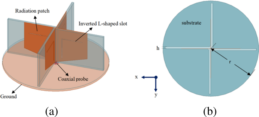
Figure 1: Proposed antenna configuration. (a) Three-dimensional view. (b) Top view of the substrate.
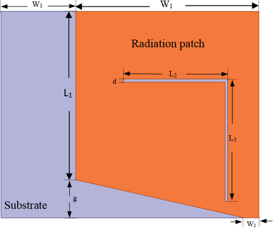
Figure 2: Structure diagram of inverted L-shaped slot radiating element.
The structure of the radiating element loaded by the inverted L-shaped slot is shown in Fig. 2. The size of the rectangular patch is WL. The bottom side of vertically placed trapezoidal patch is W, the upper bottom side W, and the height g. The length and width of the microstrip radiation patch are calculated by the following equations:
| (9) |
| (10) |
where L is the extension caused by the edge effect, and is the relative dielectric constant of the substrate, is the effective dielectric constant. At 6.5 GHz operating frequency, the length (L) and the width (W) of the radiating microstrip patch are 12.2 mm and 15.2 mm by the equation (9) and (10), respectively. L is the equivalent length of the microstrip edge effect. The width W of the 50 characteristic impedance microstrip is 2.2 mm. The coaxial probe is fed from the back of the circular reflector. The inverted L-shaped slot is used to change the current path on the radiating patch, thereby the radiation intensity of the antenna is enhanced in the +z direction. The inverted L-shaped slot has a horizontal length of L, the vertical length of L, and the slot width of d. The radiation pattern and impedance bandwidth of the antenna are optimized by adjusting the structural parameters of the antenna. The relevant structural parameters are shown in Table 1.
Table 1: Design parameters of the propeller shaped CP antenna (unit: mm)
| W | W | W | L | L | L | g | d | r | h |
| 13.4 | 2.2 | 6 | 12.8 | 7.7 | 8.8 | 2.9 | 0.2 | 20 | 1 |
IV. SIMULATION DESIGN ANALYSIS
The proposed three-dimensional compact propeller-shaped CP ceiling-mounted antenna is designed by the High Frequency Electromagnetic Simulator software (HFSS). The low cost FR4 substrate is used in the design, with the thickness of 1 mm, the relative dielectric constant of 4.4, and the loss tangent of 0.02.
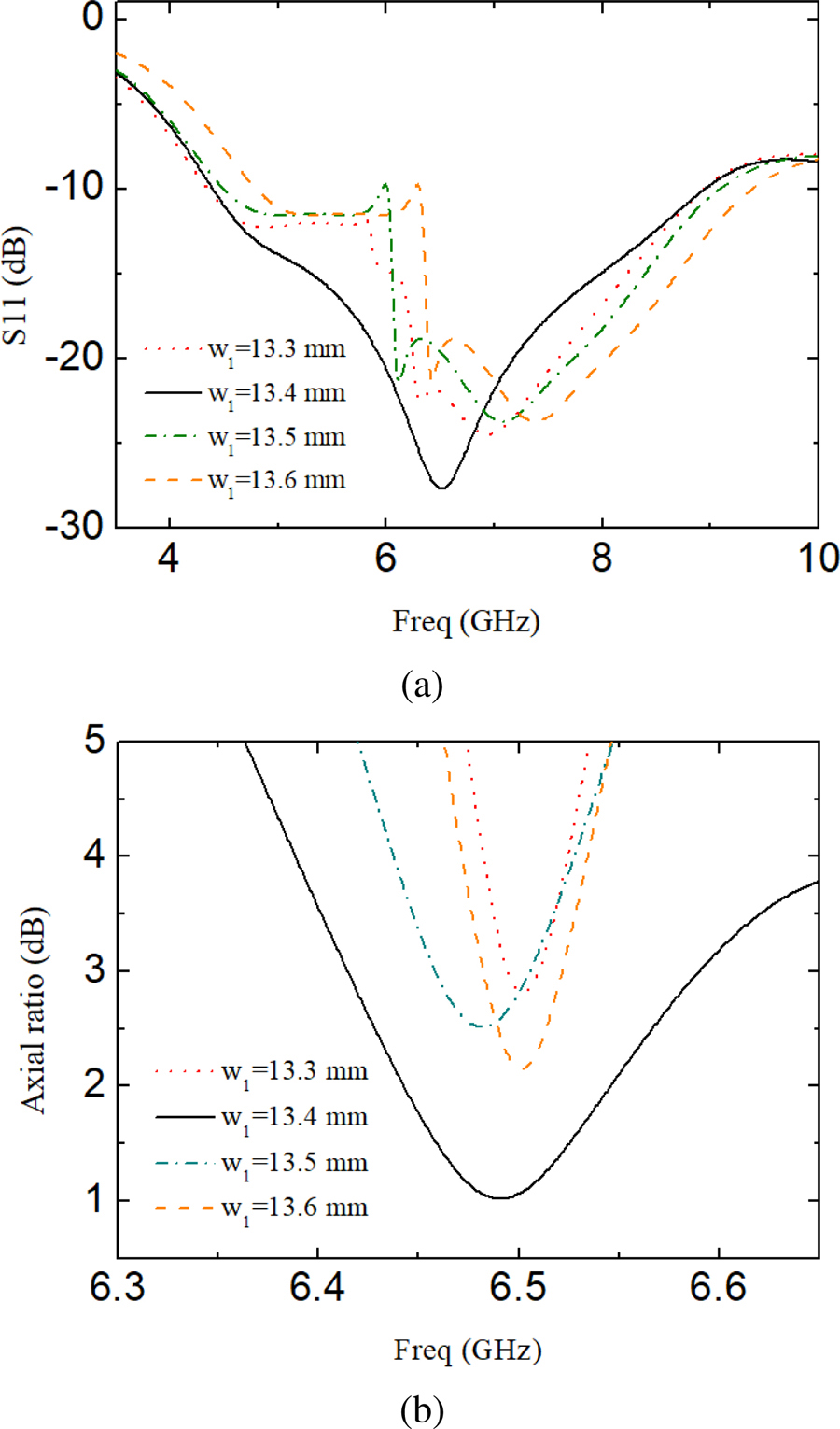
Figure 3: Simulated results of the reflection coefficient and the AR with different W. (a) Reflection coefficient. (b) Axial ratio.
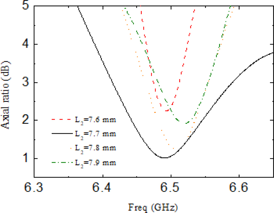
Figure 4: Simulated results of the AR with different L.
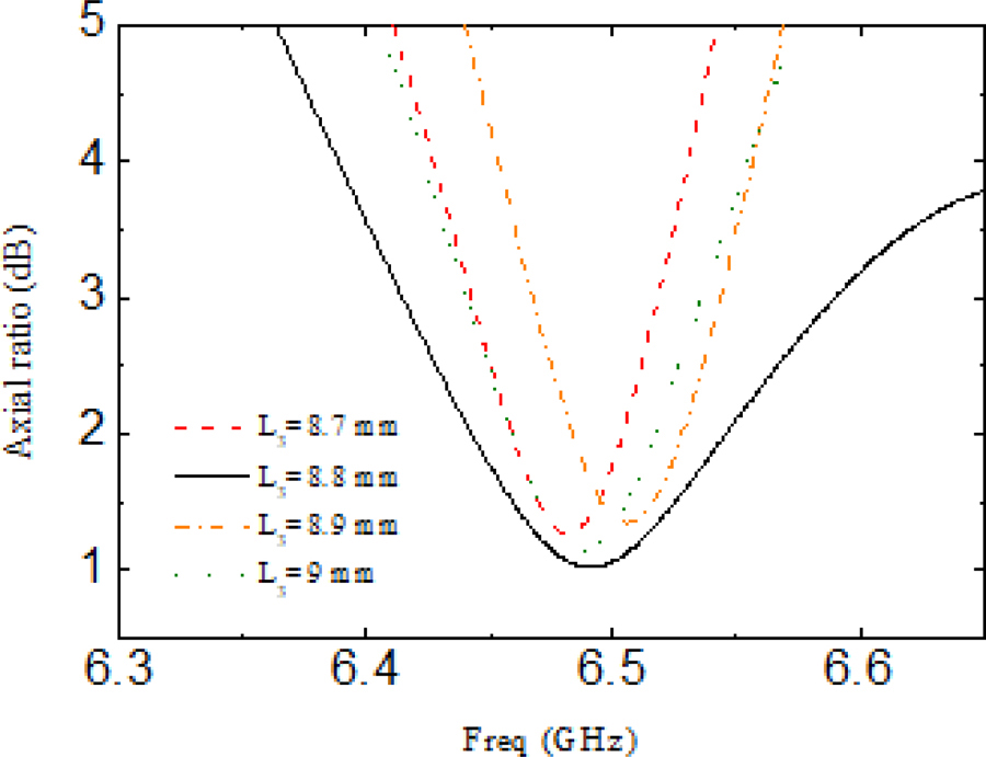
Figure 5: Simulated results of the AR with different L.
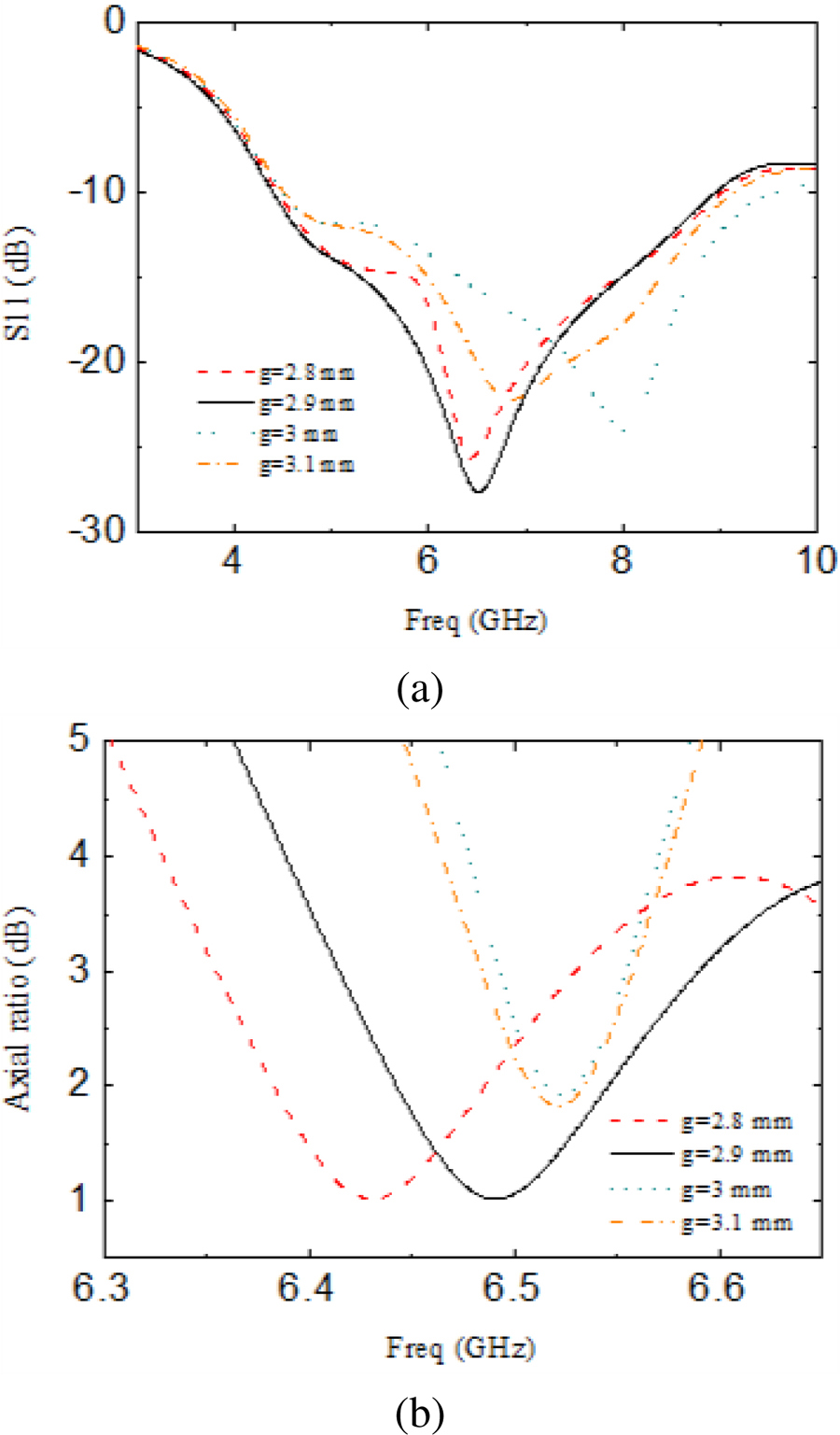
Figure 6: Simulated results of the reflection coefficient and the AR with different g. (a) Reflection coefficient. (b) Axial ratios.
The width W of the rectangular microstrip radiating patch is changed, the corresponding reflection coefficient and AR characteristics are shown in Figs. 3 (a) and (b), respectively. When the width W of the rectangular microstrip radiating patch is reduced from 13.6 mm to 13.3 mm in step of 0.1 mm, the impedance bandwidth of the antenna is influenced obviously. The result of Fig. 3 (a) shows that only when W is equal to 13.4 mm, the reflection characteristic in the band is optimal, meanwhile, the 10 dB impedance bandwidth reaches 4.54 GHz. When the value of W deviates from 13.4 mm, the reflection coefficient begins to deteriorate in the lower frequency band, and the 10 dB impedance bandwidth decreases. This is caused by resonance between the patches. Figure 3 (b) shows the AR results when W changes from 13.3 mm to 13.6 mm. It is observed that when W=13.4 mm, the 3 dB AR bandwidth achieves 185 MHz, and the AR value is 0.99 dB at the center frequency. When the value of W increases or decreases from 13.4 mm, the AR will increase, and the 3 dB AR bandwidth will decrease rapidly. Obviously, the optimal width W=13.4 mm is selected to achieve good impedance matching of the antenna and the 3 dB AR operating frequency is included in the 10 dBimpedance bandwidth.
Figure 4 shows the effect on the AR characteristics of the antenna when the horizontal length L of the inverted L-shaped slot is gradually increased from 7.6 mm to 7.9 mm in steps of 0.1 mm. Among them, when L is greater than 7.7 mm, the AR characteristic deteriorates, and the working frequency band shifts to the high frequency at the same time. When L is less than 7.7 mm, the AR value slightly increases, and the 3 dB AR bandwidth decreases. When L=7.7 mm, the 3 dB AR bandwidth is the widest, and the AR value of the center frequency is the smallest.
Figure 5 shows the AR results of the antenna when the vertical length L of the inverted L-shaped slot changes. When L=8.8 mm, the axial ratio bandwidth is the widest, and the circular polarization characteristic is the best. When the length of L deviates from 8.8 mm, the 3 dB AR bandwidth reduces sharply.
Figure 6 shows the simulation results of the reflection coefficient and the AR of the antenna when the height g of the trapezoidal microstrip is varied, respectively. Figure 6 (a) shows that when g is equal to 2.9 mm, there are excellent reflection coefficient and in-band characteristics. Figure 6 (b) shows that when g=2.9 mm, the center frequency is near 6.5 GHz. At this time, the antenna has a small AR value and the AR bandwidth is wide. When the value of g is less than 2.9 mm, the 3 dB AR frequency band moves to a low frequency. When the value of g is greater than 2.9 mm, the 3 dB AR frequency band moves to a high frequency. The AR bandwidth reduces rapidly and the performance in the band deteriorates.
V. EXPERIMENT RESULTS
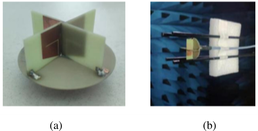
Figure 7: Antenna photograph and anechoic chamber photograph. (a) Photograph of the fabricated CP antenna. (b) Measurement photograph of the CP antenna.
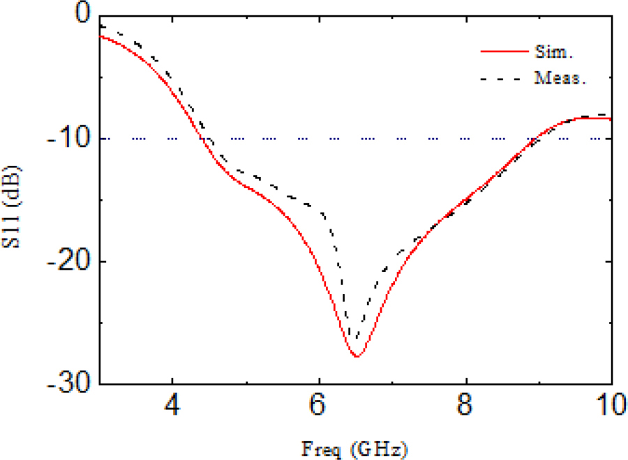
Figure 8: Simulation and measurement results of the proposed antenna’s reflection coefficient.
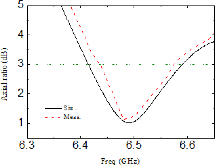
Figure 9: Simulated and measured results of the AR curve of the proposed antenna.
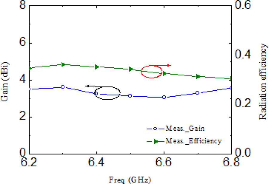
Figure 10: Measured results of the antenna gain and radiation efficiency.
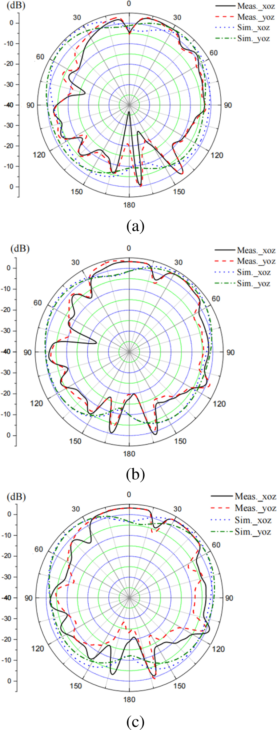
Figure 11: The measured CP radiated patterns on xoz plane and yoz plane, respectively. (a) 6.45 GHz. (b) 6.5 GHz. (c) 6.6 GHz.
To verify the simulation results, a propeller-shaped CP ceiling antenna was fabricated and measured. The actual measurement is conducted in an anechoic chamber with Agilent’s vector network analyzer (VNA, Agilent E8362B). Figure 7 is the measurement photo of the CP antenna. Figure 8 is the simulation and measurement curve of the final antenna reflection coefficient. The measurement result shows that the frequency band with the reflection coefficient less than 10 dB is from 4.51 GHz to 9.01 GHz, and the bandwidth is 4.5 GHz, which is slightly smaller than the simulation result.
Figure 9 shows the measured AR characteristic curve. The frequency band range is from 6.44 GHz to 6.58 GHz with the AR less than 3 dB. The 3 dB AR bandwidth is 140 MHz and the 3 dB AR fractional bandwidth of the antenna is 2.2%. The measurement curve of the CP antenna gain and the radiation efficiency is shown in Fig. 10. It is well known that as the size of the antenna is reduced, so does the efficiency. For the antenna proposed in this paper, in addition to the size of the antenna, the width d of the inverted L-shaped slot on the radiation patch and the dielectric constant of the substrate material will also affect the radiation efficiency measurement. The radiation efficiency of the antenna is 35% to 39% in the range of 6.2 GHz to 6.8 GHzin Fig. 10.
Figure 11 shows the simulated and measured xoz plane and yoz plane radiation patterns of far-field radiation at different working frequencies of 6.45 GHz, 6.5 GHz, and 6.6 GHz, respectively. The radiation patterns are all half-space radiation. Due to the size of the via of the reflector and the manufacturing process, a certain amount of radiation leakage occurs on the back side.
Table 2: Comparison of the published ceiling-mounted antennas
| Ref. | IBW (S1110 dB) GHz |
ARBW (AR3 dB) GHz |
Feeding Method | Radiation Zero Point | Antenna Size () | Peak Gain (dBi) |
| [15] | 2-2.9 | - | Side | yes | 1.61.60.35 | 7.8 |
| [16] | 1.98-3.55 | - | Back | yes | 0.070.070.85 | 3.5 |
| [17] | 0.698-0.960 1.35-3.8 |
- | Back | no | 1.20.780.05 | - |
| [18] | 0.65-6 | - | Back | yes | 0.90.92.67 | 6 |
| [19] | 0.865-1.005 | 0.861-0.92 | Back | no | 0.30.90.9 | 4.3 |
| [25] | 2.41-2.47 | - | Back | yes | 0.50.50.65 | 0.4 |
| This paper | 4.4-8.94 | 6.44-6.58 | Back | no | 0.40.40.98 | 3.22 |
IBW=impedance bandwidth, ARBW=axial ratio bandwidth
Table 2 compares the various types of ceiling antennas working in different frequency bands that have been published with the ceiling antennas proposed in this article. The key structural parameters and electrical parameters are listed in Table 2. Most of the ceiling-mounted antennas use coaxial back-feed excitation and the polarization characteristic is LP with a relatively large area. The fatal flaw in the comparison literature is that the ceiling-mounted antenna has a radiation zero point in the radiation direction. The propeller-type ceiling antenna proposed in this paper does not produce a radiation zero point in the radiation direction, meanwhile, it obtains a higher gain in a relatively small volume.
VI. CONCLUSION
In this paper, a novel ceiling-mounted CP antenna is proposed and implemented. The antenna is loaded with the inverted L slot structure on a microstrip radiation patch. Four cross-placed radiating elements are welded on the reflector substrate whose back has ground to realize half-space CP radiation. The measured impedance bandwidth reaches 4.5 GHz. The 3 dB AR bandwidth is 140 MHz. The gain fluctuated from 3.04 dBi to 3.22 dBi in the range of 6.2 GHz to 6.8 GHz. Because this propeller-shaped ceiling-mounted CP antenna has a compact structure and good directivity, it can be used in various wireless communication systems. It is especially suitable for, by way of example: UAVs, trains, airplanes or cabins, subway stations and other indoor places.
ACKNOWLEDGMENT
This work was supported by the Fujian Natural Science Foundation Project, grant number 2022J01823.
REFERENCES
[1] B. Qiu, Y. Xia, and Y. Li, “Gain-enhanced wideband circularly polarized antenna with a non-uniform metamaterial reflector,” Applied Computational Electromagnetics Society (ACES) Journal, vol. 37, no. 3, pp. 281-286, 2022.
[2] I. Nadeem, M. Alibakhshikenari, F. Babaeian, A. Althuwayb, B. S. Virdee, L. Azpilicueta, S. Khan, I. Huynen, and F. Falcone, “A comprehensive survey on ‘Circular Polarized Antennas’ for existing and emerging wireless communication technologies,” Journal of Physics D: Applied Physics, vol. 55, no. 3, pp. 033002, 2021.
[3] Y. Yang, B. Sun, and J. Guo, “A single-layer wideband circularly polarized antenna for millimeter-wave applications,” IEEE Trans. Antennas Propagat., vol. AP-68, pp. 4925-4929, 2020.
[4] N. Hussain, M. Jeong, A. Abbas, and N. Kim, “Metasurface-based single-layer wideband circularly polarized MIMO antenna for 5G millimeter-wave systems,” IEEE Access, vol. 8, pp.130293-130304, 2020.
[5] J. H. Kim, C. H. Jeong, and W. S. Lee, “Rotated stacked yagi antenna with circular polarization for IoT applications,” Applied Computational Electromagnetics Society (ACES) Journal, vol. 34, no. 8, pp. 1246-1249, 2019.
[6] B. Park and J. Lee, “Omnidirectional circularly polarized antenna utilizing zeroth-order resonance of epsilon negative transmission line,” IEEE Transactions on Antennas and Propagation, vol. AP-59, pp. 2717-2720, 2011.
[7] B. Li, C. Hao, and X. Sheng, “A dual-mode quadrature-fed wideband circularly polarized dielectric resonator antenna,” IEEE Antennas and Wireless Propagation Letters, vol. 8, pp. 1036-1038, 2009.
[8] B. Li, C. Hao, and X. Sheng, “A dual-mode quadrature-fed wideband circularly polarized dielectric resonator antenna,” IEEE Antennas and Wireless Propagation Letters, vol. 8, pp. 1036-1038, 2009.
[9] C. Yang, L. Yang, and M. Wang, “Wideband circularly polarized antenna with L-shaped slot,” Journal of Microwaves, vol. 28, pp. 94-96, 2012.
[10] Y. J. Zhang, X. J. Liang, and B. Zhao, “Design and realization of circular polarization cylindrical conformal antenna with omnidirectional radiation,” Manufacturing Automation, vol. 31, pp. 1245-1249, 2010.
[11] R. E. Fisk and J. A. Donovan, “A new CP antenna for television broadcast service,” IEEE Transactions on Broadcasting, vol. BC-22, pp. 91-96,1976.
[12] Y. Shi and J. Liu, “Wideband and low-profile omnidirectional circularly polarized antenna with slits and shorting-vias,” IEEE Antennas and Wireless Propagation Letters, vol. 15, pp. 686-689, 2016.
[13] Q. Y. Guo, Q. W. Lin, and H. Wong, “A high gain millimeter-wave circularly polarized Fabry–Pérot antenna using PRS-integrated polarizer,” IEEE Transactions on Antennas and Propagation, vol. AP-69, pp. 1179-1183, 2021.
[14] V. Zarei, H. Boudaghi, M. Nouri, and S. A. Aghdam, “Reconfigurable circular polarization antenna with utilizing active devices for communication systems,” Applied Computational Electromagnetics Society (ACES) Journal, vol. 30, no. 9, pp. 990-995, 2015.
[15] J. F. Keh, M. Chou, Z. C. Zhang, Q. X. An, and W. J. Liao, “A beamforming-network-based four-squint-beam array antenna for ceiling-mount access point,” IEEE Antennas and Wireless Propagation Letters, vol. 18, pp. 707-711, 2019.
[16] Y. W. Jang and H. C. Go, “A low-profile broadband 16-mm-diameter post-type monopole antenna ceiling-mounted in a building,” Microwave and Optical Technology Letters, vol. 41, pp. 395-397, 2004.
[17] K. J. Ng, M. T. Islam, A. Alevy, M. F. Mansor, and C. C. Su, “Azimuth null-reduced radiation pattern, ultralow profile, dual-wideband and low passive intermodulation ceiling mount antenna for long term evolution application,” IEEE Access, vol. 7, pp. 114761-114777, 2019.
[18] L. Zhou, Y. Jiao, Y. Qi, Z. Weng, and L. Lu, “Wideband ceiling mount omnidirectional antenna for indoor distributed antenna system applications,” IEEE Antennas and Wireless Propagation Letters, vol. 13, pp. 836-839, 2014.
[19] J. Choo, S. Yoo, and H. Choo, “Design of a ceiling-mounted reader antenna to maximize the readable volume coverage ratio for an indoor UHF RFID application,” Microwave and Optical Technology Letters, vol. 59, pp. 2136-2141, 2017.
[20] B. Y. Toh, R. Cahill, and V. F. Fusco, “Understanding and measuring circular polarization,” IEEE Transactions on Education, vol. 46, pp. 313-318, 2003.
[21] C. A. Balanis, Antenna Theory: Analysis and Design, 3rd ed, Harper & Row, New York City, 1982.
[22] G. E. Evans, Antenna Measurement Techniques, Artech House, Norwood, MA, 1990.
[23] O. Altintas, E. Unal, O. Akgol, M. Karaaslan, F. Karadag, and C. Sabah, “Design of a wide band metasurface as a linear to circular polarization converter,” Modern Physics Letters B, vol. 31, no. 30, pp. 1750274, 2017.
[24] O. Akgol, O. Altintas, E. Unal, M. Karaaslan, and F. Karadag, “Linear to left-and right-hand circular polarization conversion by using a metasurface structure,” International Journal of Microwave and Wireless Technologies, vol. 10, pp. 133-138, 2018.
[25] Y. T. Liu, C. W. Su, C. L.Tang, S. T. Fang, and K. L. Wong, “Radiation pattern control for an on-ceiling omnidirectional monopole antenna,” Microwave and Optical Technology Letters, vol. 41, pp. 106-108, 2004.
BIOGRAPHIES

Jia-Xiang Chen was born in 1998 in Fujian Province, China. He received a bachelor’s degree from Nanchang Hangkong University in 2020. He is currently working on his M.S. degree in Information and Communication Engineering at Jimei University, Fujian Province, China. His research interest is antenna techniques.

Hai-Tao Xing was born in 1983 in Shandong, China. In 2010, he obtained a master’s degree in Communication and Information Engineering from Ningbo University. At present, his main research interests are embedded systems, artificial intelligence and IoT.

Jian-Mei Huang was born in 2002 in Fujian Province, China. She is currently pursuing a B.S. degree with the Department of Communication Engineering, Jimei University, Fujian Province, China. Her research interest is antenna techniques.

Meng-Nan Wang was born in 2000 in Henan Province, China. She received a bachelor’s degree from Zhengzhou University of Aeronautics in 2022. She is currently working on her M.S. degree in Information and Communication Engineering at Jimei University, Fujian Province, China. Her research interest is chipless RFID sensors.

Zhong-Hua Ma was born in Gansu, Republic of China, in 1973. He received his Ph.D. degree in Microelectronics from Lanzhou University in 2018. His present research interests include antenna techniques, RF circuit design, RFID systems and IoT.
ACES JOURNAL, Vol. 38, No. 4, 231–239
doi: 10.13052/2023.ACES.J.380402
© 2023 River Publishers